
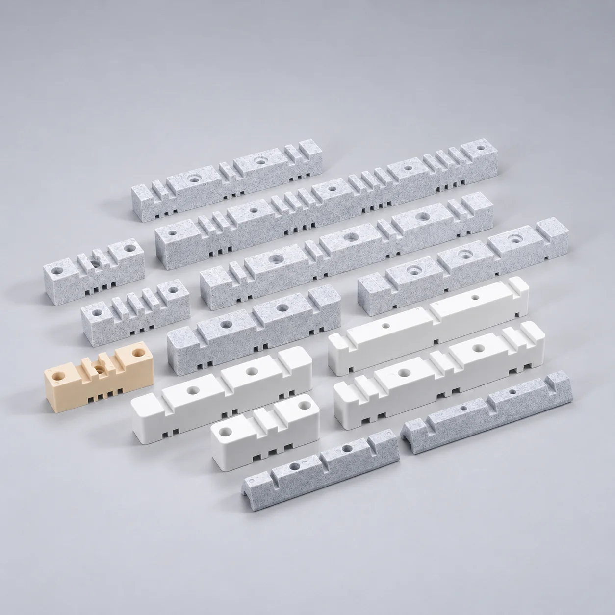
EL Ribbed Support Insulators
EL ribbed support insulators use an unsaturated polyester BMC body and brass nut inserts.
- Six listed part numbers.
- Heights from 60 to 210 mm.
- Rated voltages from 3.6 to 24 kV, depending on model.
- Model-specific creepage, low-frequency dielectric and impulse voltage data.
- Dark brown or dark red.
- Top and bottom insert arrangements listed by part number.
Descripción general
YOCL ELECTRIC EL ribbed support insulators combine an unsaturated polyester bulk moulding compound body with brass nut inserts. The ribbed body profile and insert arrangement vary by model. Dark brown and dark red colours are listed.
Six part numbers are specified, with heights from 60 to 210 mm and listed rated voltages from 3.6 to 24 kV. Rated voltage, low-frequency dielectric strength and impulse voltage resistance are provided as separate characteristics for each model.
Características
- Unsaturated polyester BMC body with a ribbed profile.
- Brass nut inserts in model-specific arrangements.
- Six part numbers with 60–210 mm heights.
- Model-specific creepage distance and electrical data.
- Dark brown or dark red colour.
Technical Specifications
| Parameter | Specification |
|---|---|
| Series | EL ribbed support insulators |
| Material | Unsaturated polyester Bulk Moulding Compound (BMC) |
| Nut inserts | Brass; various specifications listed |
| Colour | Dark brown or dark red |
| Test specification references as listed | JIS C3801; JIS C3851 |
Electrical Characteristics
| Part number | Rated voltage (kV) | Low-frequency dielectric strength (kV) | Impulse voltage resistance (kV) |
|---|---|---|---|
| 76:120 | 10 | 55 | 110 |
| EL-24 | 24 | 60 | 125 |
| EL-15 | 15 | 50 | 110 |
| EL-12 | 12 | 36 | 95 |
| EL-6M | 7.2 | 22 | 75 |
| EL-3M | 3.6 | 16 | 60 |
Mechanical Characteristics
| Part number | Sustained bending strength, 1 min (source unit: kg) | Tensile strength (source unit: kg) | Torque strength (source unit: kg-m) |
|---|---|---|---|
| 76:120 | 400 | 1500 | 25 |
| EL-24 | 300 | >1500 | >25 |
| EL-15 | 400 | >1500 | >25 |
| EL-12 | 300 | >2000 | >25 |
| EL-6M | 400 | >1200 | >25 |
| EL-3M | 400 | >1200 | >25 |
The mechanical figures retain the source unit labels kg and kg-m; no force-unit conversion is applied. The greater-than signs are part of the listed specifications. Torque strength is not a recommended installation tightening torque.
Dimension
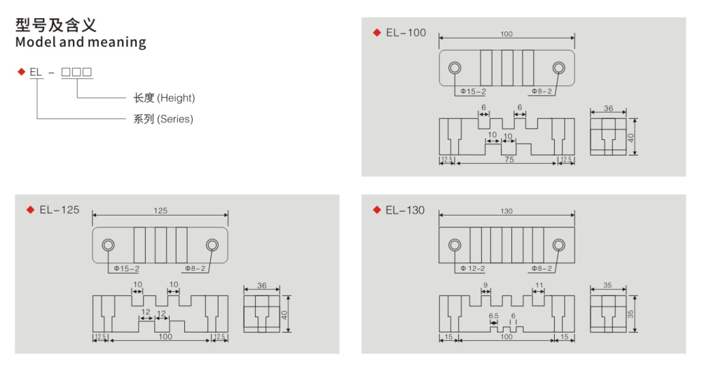
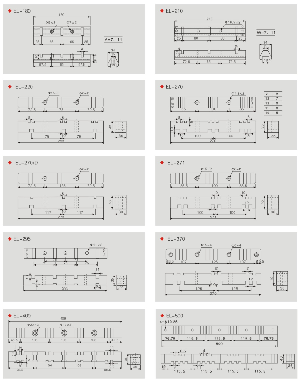
| Part number | End diameters A/B (mm) | Height H (mm) | Creepage distance (mm) |
|---|---|---|---|
| 76:120 | 76 | 120 | 300 |
| EL-24 | 70 | 210 | 356 |
| EL-15 | 70 | 142 | 210 |
| EL-12 | 58 | 130 | 172 |
| EL-6M | 70 | 90 | 125 |
| EL-3M | 70 | 60 | 88 |
Insert Arrangement
| Part number | Top A1 | Top A2 | Top A3 | Top AX (mm) | Top AY (mm) | Bottom S1 |
|---|---|---|---|---|---|---|
| 76:120 | M16 | –/M8 | – | – | – | – |
| EL-24 | M10/M12 | – | M6/M8 | – | 36/40 | M10/M12/M16 |
| EL-15 | M8/M10 | – | M6/M8 | – | 36/40 | M10/M12/M16 |
| EL-12 | M10 | M8 | – | 36 | – | M10/M16 |
| EL-6M | M10 | M8 | – | 40 | – | M10 |
| EL-3M | M10 | M8 | – | 40 | – | M10 |
A1, A2 and A3 identify the top insert positions; S1 is the central bottom insert position. AX and AY retain the labelled top spacing values. A dash represents an unlisted position or dimension. Slash-separated entries retain the available designations in the source and should be specified when requesting the final insert layout.
Selection Guide
Choose the part number by its rated voltage, height, end diameter and creepage distance, then specify the top and bottom insert arrangement. For example, EL-6M and EL-3M share a 70 mm end diameter, but differ in height, creepage distance and rated voltage. The part number 76:120 is retained as listed and has its own electrical and insert data.
Ordering Information
For a quotation, specify the part number, quantity, colour, top insert designation, bottom insert designation and required mounting spacings. Request the final insert layout for any slash-separated thread or spacing options.