
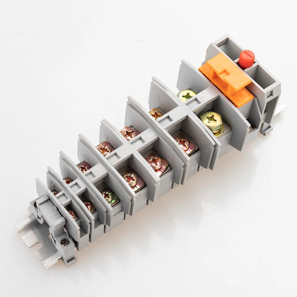
JH1A Series Screw DIN Rail Terminal Blocks
YOCL Electric JH1A screw DIN rail terminal blocks provide screw-clamped conductor connections for industrial control and electrical assemblies. Nine models offer individual conductor capacities, electrical ratings, dimensions and screw sizes. The grey terminals use combination screws with spring washers for self-locking action during tightening. Select the model by its conductor range, circuit requirements and mounting rail compatibility.
- Nine JH1A models
- Rated currents of 17.5–125 A, depending on model
- 380 V or 500 V ratings, depending on model
- 35 mm and 28 mm mounting rail widths
Aperçu
YOCL Electric JH1A screw DIN rail terminal blocks connect conductors and organize circuits in industrial control cabinets, distribution panels and equipment wiring. The series uses direct screw clamping, with combination screws applying the clamping force to the conductor.
Spring washers in the screw assembly deform during tightening to provide a self-locking action. Nine grey terminal models are available, each with its own conductor capacity, rated current, rated voltage, dimensions, screw thread and partition reference.
Caractéristiques
- Screw-clamped connection for conductor termination.
- Combination screws with spring washers for self-locking action during tightening.
- Nine model configurations for different conductor and circuit requirements.
- Individual electrical ratings: 17.5–125 A and 380 V or 500 V, depending on model.
- Model-specific screw threads: M3, M4, M5 or M8.
- Partition references matched to individual models.
- Rail mounting: 35 mm and 28 mm mounting rail widths are specified for the series.
Spécifications techniques
| Parameter | Specification |
|---|---|
| Brand | YOCL Électrique |
| Series | JH1A |
| Product type | Screw DIN rail terminal block |
| Connection method | Screw connection |
| Color | Grey |
| Models | 9 |
| Conductor types | Single-strand conductor and multi-strand wire |
| Conductor capacity across the series | 0.75–36 mm²; use the individual model range below |
| Rated current across the series | 17.5–125 A; model dependent |
| Rated voltage | 380 V or 500 V; model dependent |
| Screw thread | M3, M4, M5 or M8; model dependent |
| Mounting rail widths | 35 mm / 28 mm |
| Ambient temperature | -25°C to +55°C |
| Relative humidity | 90% |
| Pollution degree | 3 |
| Dimension format | Length × width × height (L × W × H), mm |
Model Specifications
Conductor capacities are expressed in mm². Dimensions are expressed in millimeters, in the order L × W × H.
| Model | Single-strand conductor | Multi-strand wire | Rated current | Rated voltage | Dimensions L × W × H | Screw thread |
|---|---|---|---|---|---|---|
| JH1A-1.5 | 0.75–1.5 mm² | 0.75–1.5 mm² | 17.5 A | 500 V | 44.5 × 38 × 7.5 mm | M3 |
| JH1A-2.5 | 0.75–1.5 mm² | 0.75–1.5 mm² | 24 A | 500 V | 46.5 × 42.5 × 9.5 mm | M4 |
| JH1A-2.5S | 1–2.5 mm² | 1–2.5 mm² | 17.5 A | 500 V | 54 × 63.5 × 12 mm | M4 |
| JH1A-2.5RD | 1–2.5 mm² | 1–2.5 mm² | 20 A | 380 V | 57 × 65.5 × 16 mm | M4 |
| JH1A-6 | 2.5–6 mm² | 2.5–6 mm² | 41 A | 500 V | 52.5 × 43.5 × 13.5 mm | M5 |
| JH1A-10 | 6–10 mm² | 6–10 mm² | 57 A | 500 V | 54 × 46.5 × 16.5 mm | M5 |
| JH1A-16 | 10–16 mm² | 10–16 mm² | 76 A | 500 V | 54.5 × 46.5 × 19 mm | M5 |
| JH1A-25 | 10–25 mm² | 10–25 mm² | 101 A | 500 V | 60.5 × 52 × 20 mm | M8 |
| JH1A-35 | 16–36 mm² | 16–36 mm² | 125 A | 500 V | 66.5 × 52 × 24 mm | M8 |
Select conductor capacity and electrical ratings from the row for the chosen model. For example, JH1A-2.5S is rated at 17.5 A / 500 V, while JH1A-2.5RD is rated at 20 A / 380 V and has different dimensions.
Partition References
| Terminal model | Partition reference |
|---|---|
| JH1A-1.5 | 1.5G |
| JH1A-2.5 | 2.5G |
| JH1A-2.5S | 2.5SG |
| JH1A-2.5RD | 2.5RGD |
| JH1A-6 | 6G |
| JH1A-10 | 10G |
| JH1A-16 | 10G |
| JH1A-25 | 2.5G |
| JH1A-35 | 35G |
Specify the terminal model together with its partition reference when requesting accessories.
Screw Connection and Rail Mounting
The conductor is secured by tightening the combination screw. Screw size is tied to the terminal model: M3 for JH1A-1.5; M4 for JH1A-2.5, JH1A-2.5S and JH1A-2.5RD; M5 for JH1A-6, JH1A-10 and JH1A-16; and M8 for JH1A-25 and JH1A-35.
The series is specified for 35 mm and 28 mm mounting rail widths. Select the terminal and rail together to match the intended mounting system. Check the model’s dimensions when planning the terminal arrangement inside the panel.
Model Selection
- Match the conductor. Use the listed range for the selected model and conductor type.
- Check the electrical ratings. Select the model according to its rated current and rated voltage.
- Check available space. Compare the model’s L × W × H dimensions with the panel layout.
- Specify the mounting rail. State the required 35 mm or 28 mm rail width.
- Identify accessories. Include the terminal model and partition reference in the enquiry.
JH1A model designations identify different configurations. Use the corresponding specification row when selecting a terminal.
Applications
- Industrial control cabinets
- Electrical distribution panels
- Automation equipment
- Machinery electrical systems
- Equipment internal wiring
- Rail-mounted control and power circuit terminal assemblies
Select the model according to the conductor cross-section, circuit ratings and installation requirements.
Ordering Information
When requesting a quotation from YOCL Électrique, provide:
- JH1A model and required quantity
- Conductor cross-section and single-strand or multi-strand construction
- Required current and voltage ratings
- Mounting rail width
- Required partition reference
Each model has its own conductor range, electrical ratings, dimensions and screw thread. Include these requirements with the model number to support product selection.