
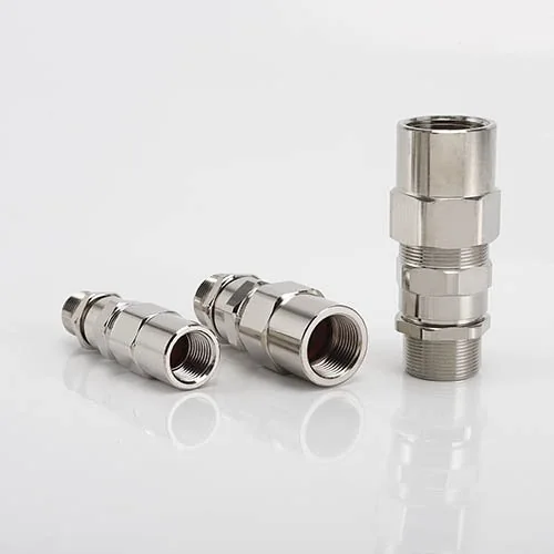
BDM-21-II Flameproof Ex d Barrier Cable Gland for Conduit
BDM-21-II single compression armored barrier cable gland with a female connection for externally threaded steel pipe or flexible conduit.
- Outer clamping seal and inner putty compound barrier.
- Brass, nickel-plated brass, SS304 or SS316 body options.
- IP66, IP67 and IP68 (1 m, 1 h).
- 20 sizes with separately specified entry AG and conduit AG(F) threads.
- G-thread options for Ex e and Ex t only.
Visão Geral
The YOCL ELECTRIC BDM-21-II Flameproof Ex d Barrier Cable Gland for Conduit uses a single compression armored construction with an outer clamping seal and an inner putty compound barrier. It includes a female threaded conduit connection. The hexagonal metal body is available in brass, nickel-plated brass, SS304 and SS316.
The supplied specification lists hazardous-area applications in Zones 1, 2, 21 and 22. Metric and NPT options are listed for the Ex applications described below; G-thread options are restricted to increased safety and dust-protection applications.
The conduit end accepts an externally threaded steel pipe or flexible conduit while the gland retains the armored cable.
Características
- Compound barrier construction: Inner putty compound sealing with an outer clamping seal.
- Hexagonal body: Defined wrench flats for handling during assembly.
- Armored cable selection: Model-specific inner sheath, outer sheath and armor thickness data.
- Body material options: Brass, nickel-plated brass, SS304 and SS316.
- Thread options: Standard metric sizes and NPT/G nominal sizes, with separately listed CNEx custom metric thread options.
Especificações Técnicas
| Parâmetro | Especificação |
|---|---|
| Modelo | BDM-21-II |
| Type | Single compression armored barrier type for conduit connection |
| Sealing | Outer clamping seal; inner putty compound barrier |
| Body material options | Brass; nickel-plated brass; SS304; SS316 |
| Sealing material options | Silicone rubber; neoprene; PTFE (Teflon); PA6 |
| Operating temperature options | −40 °C to +100 °C / −60 °C to +80 °C, depending on configuration |
| Supplied Ex marking | Ex db IIC Gb; Ex eb IIC Gb; Ex tb IIIC Db, subject to thread configuration |
| Ingress protection | IP66; IP67; IP68 (1 m, 1 h) |
| Listed hazardous area applications | Zone 1; Zone 2; Zone 21; Zone 22 |
| Thread options | Metric; NPT; BSP (G) |
| G-thread application restriction | Ex e and Ex t only; not listed for Ex d |
| Stated flammability classification | UL 94 V-0 |
| Approvals stated in supplied specification | IECEx; ATEX; EAC (CUTR); CNEx; CCC |
| Standards listed in supplied specification | IEC/EN 60079-0; IEC/EN 60079-1; IEC/EN 60079-31; IEC/EN 60529; GB 3836 |
| Standard accessories | Nylon washer and locknut |
| Optional accessories | Earth tag; PVC shroud; serrated washer; red fibre washer; A/B putty compound |
Temperature limits and approval scope depend on the selected configuration. The supplied data does not map the temperature options to sealing materials or provide certificate numbers. UL 94 V-0 is the stated flammability classification; the specific material scope is not identified.
Dimensão
Cable Selection and Equipment Entry
Dimensions are in millimetres, except nominal inch thread sizes. AG is the equipment-side entry thread.
| Size | Metric AG | NPT/G AG (inch) | Inner sheath A (mm) | Outer sheath B (mm) | Armor range h (mm) |
|---|---|---|---|---|---|
| 16A | M16×1.5 | 3/8 | <8 | 5.5–12 | 0.3–1.0 |
| 16B | M16×1.5 | 3/8 | <8 | 9.5–16 | 0.3–1.0 |
| 20A | M20×1.5 | 1/2 | <11 | 5.5–12 | 0.3–1.0 |
| 20B | M20×1.5 | 1/2 | <11 | 9.5–16 | 0.3–1.0 |
| 20C | M20×1.5 | 1/2 | <15 | 12.5–20.5 | 0.3–1.0 |
| 25B | M25×1.5 | 3/4 | <15 | 12.5–20.5 | 0.3–1.0 |
| 25C | M25×1.5 | 3/4 | <21 | 17–26 | 0.4–1.2 |
| 32B | M32×1.5 | 1 | <21 | 17–26 | 0.4–1.2 |
| 32C | M32×1.5 | 1 | <27 | 22–33 | 0.4–1.4 |
| 40B | M40×1.5 | 1-1/4 | <27 | 22–33 | 0.6–1.9 |
| 40C | M40×1.5 | 1-1/4 | <33 | 28–41 | 0.6–2.2 |
| 50B | M50×1.5 | 1-1/2 | <33 | 28–41 | 0.8–2.3 |
| 50C | M50×1.5 | 1-1/2 | <42 | 36–52.6 | 0.8–2.3 |
| 63B | M63×1.5 | 2 | <42 | 36–52.6 | 0.9–2.4 |
| 63C | M63×1.5 | 2 | <54.5 | 46–64 | 0.9–2.4 |
| 75B | M75×1.5 | 2-1/2 | <54.5 | 46–64 | 0.9–2.4 |
| 75C | M75×1.5 | 2-1/2 | <66 | 57–78 | 0.9–2.4 |
| 80 | M80×1.5 | 3 | <66 | 57–78 | 0.9–2.4 |
| 90 | M90×1.5 | 3 | <75 | 68–88 | 0.9–2.8 |
| 100 | M100×1.5 | 4 | <90 | 83–103 | 0.9–2.8 |
Female Conduit Connection and Dimensions
AG(F) is the female connection for an externally threaded conduit. It can differ from the equipment entry thread AG. Specify the thread standard on both ends; the nominal NPT/G values do not make these standards interchangeable.
| Size | Metric AG(F) | G/NPT AG(F) (inch) | Maximum size D (mm) | Body length L1 (mm) | Entry thread length L (mm) |
|---|---|---|---|---|---|
| 16A | M16×1.5 | 3/8 | 29 | 75 | 16 |
| 16B | M16×1.5 | 3/8 | 29 | 75 | 16 |
| 20A | M20×1.5 | 1/2 | 29 | 77 | 16 |
| 20B | M20×1.5 | 1/2 | 29 | 77 | 16 |
| 20C | M25×1.5 | 3/4 | 37 | 78 | 16 |
| 25B | M25×1.5 | 3/4 | 37 | 78 | 16 |
| 25C | M32×1.5 | 1 | 44 | 90 | 16 |
| 32B | M32×1.5 | 1 | 44 | 90 | 18 |
| 32C | M40×1.5 | 1-1/4 | 55 | 97 | 18 |
| 40B | M40×1.5 | 1-1/4 | 55 | 97 | 18 |
| 40C | M50×1.5 | 1-1/2 | 67 | 103 | 18 |
| 50B | M50×1.5 | 1-1/2 | 67 | 103 | 20 |
| 50C | M63×1.5 | 2 | 73 | 111 | 20 |
| 63B | M63×1.5 | 2 | 73 | 111 | 21 |
| 63C | M75×1.5 | 2-1/2 | 89 | 136 | 21 |
| 75B | M75×1.5 | 2-1/2 | 89 | 136 | 22 |
| 75C | M90×2 | 3-1/2 | 105 | 146 | 22 |
| 80 | M90×2 | 3-1/2 | 105 | 146 | 22 |
| 90 | M115×2 | 4 | 115 | 155 | 23 |
| 100 | M120×2 | 4-1/2 | 130 | 155 | 24 |
L1 is the body length beyond the entry thread; L is the entry thread length, following the source drawing.
Custom Metric Threads — CNEx Configurations
The supplied specification lists the following non-standard metric threads for CNEx customization. Availability and the applicable certificate scope must be matched to the selected configuration; this list does not extend these custom threads to every approval listed above.
| Nominal thread diameter | Available pitch (mm) |
|---|---|
| M12 | 1.5 |
| M18 | 1.5 |
| M22 | 1.5 |
| M24 | 1.5 |
| M25 | 2.0 |
| M27 | 1.5 / 2.0 |
| M28 | 1.5 / 2.0 |
| M30 | 2.0 |
| M33 | 1.5 / 2.0 |
| M36 | 1.5 / 2.0 |
| M40 | 2.0 |
| M42 | 1.5 / 2.0 |
| M48 | 2.0 |
| M50 | 2.0 |
| M60 | 1.5 |
| M64 | 2.0 |
| M75 | 2.0 |
| M80 | 2.0 |
| M85 | 3.0 |
| M90 | 2.0 |
| M100 | 2.0 |
Custom-thread cable ranges and external dimensions are not separately supplied. Where two pitches are listed, specify the required pitch.
Accessories and Ordering
Specify BDM-21-II size, body material, both entry AG and female conduit AG(F) thread standards and sizes, cable sheath diameters, armor thickness and temperature configuration. G-thread options are listed for Ex e and Ex t only.
The barrier uses compatible inner putty compound. A/B compound is listed as an optional accessory, so specify its supply if it is not already available separately. Standard accessories are a nylon washer and locknut. Optional accessories include an earth tag, PVC shroud, serrated washer and red fibre washer.
Compound formulation, curing requirements and installation torque should follow the documentation for the delivered configuration.