VO-NLW Internal Thread Metal Cable Glands (Metric Thread)
VO-NLW internal thread metal cable glands provide cable entry and clamping for enclosures with metric threaded connections. The catalog lists 40 models from M12 to M100.
- Model-specific cable ranges span 3–80 mm across the series.
- Body material options listed: nickel-plated brass, SS304 and SS316L; PA claw and NBR seals.
- Source-stated IP68 applies within the specified cable range with the O-ring properly seated.
- Check thread, mounting hole, GL and spanner size in the model table.
Übersicht
VO-NLW Internal Thread Metal Cable Glands provide cable entry and clamping at equipment housings. The catalog shows 40 metric thread models covering M12 to M100, with model-specific cable clamping ranges and mounting dimensions.
Merkmale
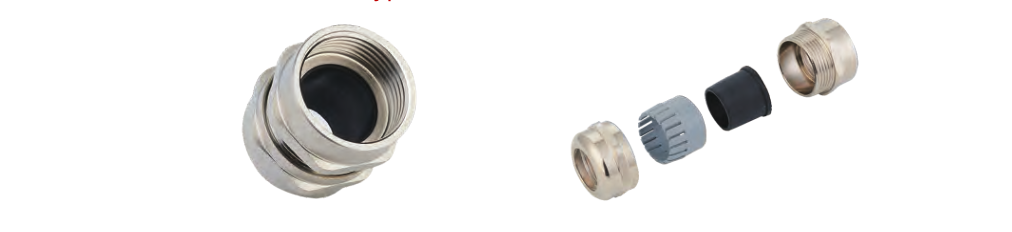
- Internal thread construction: the illustrated metal body, PA claw and NBR sealing components form a cable entry fitting.
- Model-specific fit: choose the thread, cable diameter range and mounting hole together; the series covers cable diameters from 3 to 80 mm across its listed models.
- Catalog-stated IP68: the source conditions this protection degree on using cable within the specified clamping range and properly seating the O-ring. No test report was supplied with the images.
- Material choices: the source lists nickel-plated brass, SS304 and SS316L body options without mapping them to individual codes.
Technische Daten
| Parameter | Catalog specification |
|---|---|
| Product type | Internal thread metal cable gland |
| Serie | VO-NLW |
| Metric thread range | M12–M100, model-dependent pitch |
| Listed models | 40 |
| Body material options | Nickel-plated brass, SS304 or SS316L; exact material per model not given |
| Claw | PA |
| Sealing components | NBR |
| Protection degree | IP68 stated in source for specified cable size and seated O-ring |
| Static temperature | −40 to +100 °C; short-term up to +120 °C |
| Dynamic temperature | −20 to +80 °C; short-term up to +100 °C |
| Color | Metallic |
The source also mentions ISO 9001 and TÜV but provides no certificate or model-specific approval document. Those claims are not presented as product certifications here. Chemical resistance and customization are likewise not specified by model.
Abmessung
The source labels the thread outside diameter, mounting hole diameter, thread length GL and spanner size. Cable ranges below are shown from minimum to maximum diameter; the original table printed the same endpoints in descending order. All dimensions are in millimeters. A slash in spanner size is retained exactly as supplied because the catalog does not define which flats each number refers to.
| Model | Thread | Cable diameter range (mm) | Thread OD (mm) | Mounting hole (mm) | GL (mm) | Spanner size (mm) |
|---|---|---|---|---|---|---|
| VO-M12-NLW | M12×1.5 | 3–6.5 | 12 | 12–12.2 | 7 | 14 |
| VO-M14-NLW | M14×1.5 | 4–8 | 14 | 14–14.2 | 7 | 17 |
| VO-M16-NLW | M16×1.5 | 4–8 | 16 | 16–16.2 | 8 | 18 |
| VO-M18-NLW | M18×1.5 | 5–10 | 18 | 18–18.2 | 8 | 20 |
| VO-M20-NLW | M20×1.5 | 6–12 | 20 | 20–20.2 | 8 | 22 |
| VO-M22-NLW | M22×1.5 | 10–14 | 22 | 22–22.2 | 8 | 24 |
| VO-M24-NLW | M24×1.5 | 10–14 | 24 | 24–24.2 | 9 | 24/27 |
| VO-M25A-NLW | M25×1.5 | 10–14 | 25 | 25–25.2 | 9 | 24/27 |
| VO-M25B-NLW | M25×1.5 | 8–16 | 25 | 25–25.2 | 9 | 27 |
| VO-M25C-NLW | M25×1.5 | 13–18 | 25 | 25–25.2 | 9 | 30/27 |
| VO-M27A-NLW | M27×1.5 | 13–18 | 27 | 27–27.2 | 9 | 30 |
| VO-M27B-NLW | M27×2 | 13–18 | 27 | 27–27.2 | 9 | 30 |
| VO-M28A-NLW | M28×1.5 | 13–18 | 28 | 28–28.2 | 9 | 30 |
| VO-M28B-NLW | M28×2 | 13–18 | 28 | 28–28.2 | 9 | 30 |
| VO-M30A-NLW | M30×1.5 | 13–18 | 30 | 30–30.2 | 9 | 30/32 |
| VO-M30B-NLW | M30×2 | 13–18 | 30 | 30–30.2 | 9 | 30/32 |
| VO-M32A-NLW | M32×1.5 | 15–22 | 32 | 32–32.2 | 10 | 35 |
| VO-M32B-NLW | M32×1.5 | 16–20 | 32 | 32–32.2 | 10 | 35 |
| VO-M32C-NLW | M32×2 | 15–22 | 32 | 32–32.2 | 10 | 35 |
| VO-M36A-NLW | M36×1.5 | 18–25 | 36 | 36–36.2 | 10 | 40 |
| VO-M36B-NLW | M36×2 | 18–25 | 36 | 36–36.2 | 10 | 40 |
| VO-M37A-NLW | M37×1.5 | 18–25 | 37 | 37–37.2 | 10 | 40 |
| VO-M37B-NLW | M37×2 | 18–25 | 37 | 37–37.2 | 10 | 40 |
| VO-M40A-NLW | M40×1.5 | 18–25 | 40 | 40–40.2 | 11 | 40/45 |
| VO-M40B-NLW | M40×2 | 18–25 | 40 | 40–40.2 | 11 | 40/45 |
| VO-M40C-NLW | M40×1.5 | 22–30 | 40 | 40–40.2 | 11 | 45 |
| VO-M40D-NLW | M40×2 | 22–30 | 40 | 40–40.2 | 11 | 45 |
| VO-M42A-NLW | M42×1.5 | 22–30 | 42 | 42–42.2 | 11 | 45 |
| VO-M42B-NLW | M42×2 | 22–30 | 42 | 42–42.2 | 11 | 45 |
| VO-M50A-NLW | M50×1.5 | 32–38 | 50 | 50–50.2 | 12 | 57/55 |
| VO-M50B-NLW | M50×2 | 32–38 | 50 | 50–50.2 | 12 | 57/55 |
| VO-M60A-NLW | M60×1.5 | 37–44 | 60 | 60–60.2 | 13 | 64 |
| VO-M60B-NLW | M60×2 | 37–44 | 60 | 60–60.2 | 13 | 64 |
| VO-M63A-NLW | M63×1.5 | 37–44 | 63 | 63–63.2 | 13 | 64/68 |
| VO-M63B-NLW | M63×2 | 37–44 | 63 | 63–63.2 | 13 | 64/68 |
| VO-M72-NLW | M72×2 | 42–52 | 72 | 72–72.2 | 15 | 78 |
| VO-M75-NLW | M75×2 | 42–52 | 75 | 75–75.2 | 15 | 78 |
| VO-M80-NLW | M80×2 | 50–62 | 80 | 80–80.2 | 18 | 86/88 |
| VO-M88-NLW | M88×2 | 60–70 | 88 | 88–88.2 | 18 | 98 |
| VO-M100-NLW | M100×2 | 70–80 | 100 | 100–100.2 | 20 | 110 |
Auswahlhilfe
Select the exact VO-NLW code by cable outside diameter, metric thread pitch and mounting hole. Verify the required body material and installation details with the supplier when ordering, because the model table does not assign a material variant to each code.
Abmessung