
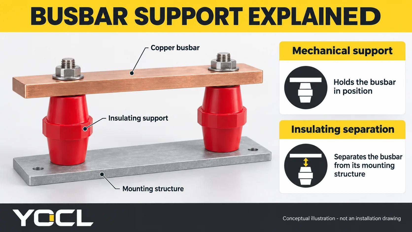
A aislante de barra colectora es un componente aislante de soporte de carga que se utiliza para montar una barra colectora y mantenerla eléctricamente separada de las partes conductoras circundantes. En cuadros eléctricos y paneles de control de baja tensión, a menudo adopta la forma de un soporte moldeado o un soporte con forma. Combina dos funciones: mantener el conductor en posición y proporcionar separación aislante en sus puntos de montaje. Descripciones del fabricante de aislantes de baja tensión identifican ambas funciones.
La barra colectora en sí es el conductor metálico, comúnmente de cobre o aluminio. El aislante es parte de la estructura que lo soporta. Comprender esa relación ayuda a distinguir un aislante de soporte de una funda, recubrimiento o cubierta colocada alrededor del conductor.
¿Qué hace un aislante de barra colectora?
Considere una barra colectora de cobre montada sobre una placa posterior metálica. Un soporte aislante adecuado proporciona una interfaz de montaje sin crear una conexión conductora directa entre la barra y la placa posterior. Su cuerpo y geometría de montaje contribuyen a la separación eléctrica requerida por el ensamblaje.
El soporte también localiza la barra mecánicamente. Mantiene la posición de montaje y transfiere las cargas a la estructura de soporte. El arreglo completo debe acomodar la carga mecánica relevante; soportar el peso de la barra es solo una parte de esa carga. Las condiciones de cortocircuito pueden someter al conductor y sus soportes a fuerzas electromagnéticas sustanciales, que requieren una evaluación a nivel de sistema. ABB’s low-voltage assembly guide addresses busbar support construction and short-circuit verification.
Installing a support does not cover the exposed copper or aluminium. A bare busbar remains an exposed conductor even when correctly mounted on insulators. Touch protection depends on the complete protective arrangement, including any required barriers, covers or enclosure.
Busbar insulator, support, clamp and insulation: the terminology
These terms describe related parts of a busbar assembly, but they do not always identify the same component.
| Term | What it describes | Important distinction |
|---|---|---|
| Busbar insulator / support insulator | An insulating component that mechanically supports or positions a busbar | Its electrical and mechanical suitability depends on the exact design |
| Stand-off insulator | A support that holds a conductor away from its mounting surface | A common construction, rather than the shape of every busbar insulator |
| Busbar support system | The arrangement of supports, mounting members and associated hardware | It can position several bars and must be evaluated as an arrangement |
| Busbar clamp | A component that retains or locates the bar | The name alone does not establish insulating material or a dielectric rating |
| Busbar insulation | A layer or enclosure around the conductor, such as heat shrink, coating or overmoulding | Covering insulation does not by itself define the mechanical support arrangement |
Eaton’s busbar documentation describes several conductor-insulation methods. Those methods explain how a bar can be covered; a support insulator explains how it is mounted and isolated from its supporting structure.
What does a busbar insulator look like?
Common low-voltage constructions include:
- Post and stand-off supports: compact moulded bodies with fixing points, often threaded inserts. Height, footprint and the insert arrangement identify the mounting geometry. YOCL SM busbar support insulators are one example of this construction.
- Stepped supports: shaped bodies with mounting positions at different levels. The steps organize the bar layout; their suitability still depends on the specific assembly. YOCL CT/CJ supports illustrate this form.
- Grooved or multi-bar arrangements: support components and retaining hardware that locate bars in defined positions. Some are assemblies of several parts. Verify the function and specification of each part rather than assuming every clamp is an electrical insulator.
Ribbed bodies also appear in higher-voltage support ranges, including YOCL EL ribbed support insulators. The ribs change the surface path between conductive fixing points. The model’s drawing, declared creepage distance and voltage data explain its application more reliably than appearance alone.
Materials and metal inserts
Glass-fibre-reinforced polyester moulding compounds are used in commercial low-voltage insulators. Other busbar support designs use engineering thermoplastics such as polyamide. These are documented examples, not a universal material specification for all supports. See nVent’s low-voltage insulator range and Rittal’s RiLine DC support documentation.
Metal threaded inserts provide fastening interfaces. Their presence does not make the whole component a conductive spacer: the insulating body separates the relevant mounting interfaces. The exact insert arrangement, thread and permissible fasteners come from the model drawing. A familiar colour or outline cannot establish the compound grade or electrical rating.
Clearance and creepage describe different separation paths
Two terms help explain the electrical function of a busbar support:
- Clearance measures the shortest path through air between conductive parts.
- Creepage distance measures the shortest path along an insulating surface between conductive parts.
Weidmuller’s clearance and creepage guide explains this distinction and the importance of the application conditions.
For example, a stand-off can raise a bar above a backplate, while the surface profile of the support influences the path along its body. Neither path should be assumed to equal the support’s overall height. Nearby bolts, brackets and conductors also affect the finished geometry.
Required distances depend on the applicable insulation design and conditions. A single height or spacing value cannot describe every voltage, environment and busbar arrangement. Rittal’s support-system documentation explicitly calls for checking clearance and creepage in the final application.
What do busbar insulator specifications mean?
A drawing describes the physical interface; electrical and mechanical data describe performance under stated conditions. Reading them separately avoids several common misunderstandings.
| Especificación | What it tells you | What it cannot establish on its own |
|---|---|---|
| Height, footprint and mounting centres | The support’s geometry and mounting position | The actual clearance or creepage throughout the assembly |
| Thread size and insert depth | The fastening interface | A universal tightening torque or interchangeable metric/imperial hardware |
| Declared operating or rated voltage | The voltage duty identified by the manufacturer, with its stated scope | That every layout using the component has the same rating |
| Dielectric withstand / test voltage | Performance in a specified electrical test | A continuous operating-voltage rating at that test value |
| Mechanical strength | Resistance to the declared load or test, in the stated direction | The short-circuit withstand of an arbitrary busbar assembly |
| Material and flammability classification | The compound or stated material-test property | Complete electrical suitability or finished-equipment certification |
The operating-versus-test distinction is visible in MALTEP’s insulator data, which lists nominal voltage and dielectric withstand separately. Likewise, a mechanical or torque-strength test result should not be converted into an installation tightening instruction without the manufacturer’s specified mounting data.
If a material is described as UL 94 V-0, that is a flammability classification under the relevant test conditions. It does not establish a voltage rating, make the material absolutely non-flammable, or certify the complete panel. UL’s plastics combustion-testing explanation describes the scope of these classifications.
Why component data and assembly ratings remain separate
A busbar assembly combines conductors, supports, fasteners, mounting structures and insulation distances. Changing the support type, bar geometry or support span can change its mechanical behaviour. The component’s electrical test data and the assembled system’s short-circuit performance therefore answer different questions.
IEC 61439-1 sets general rules and verification requirements for low-voltage switchgear and controlgear assemblies; assembly conformity also involves the relevant subsequent part of the series. A component datasheet helps define the design inputs, while the complete assembly requires its own applicable verification.
For model drawings and construction choices, explore YOCL’s busbar supports and insulators range. Use the exact model’s mounting, electrical and mechanical information when moving from understanding the component to specifying it for a particular assembly.