
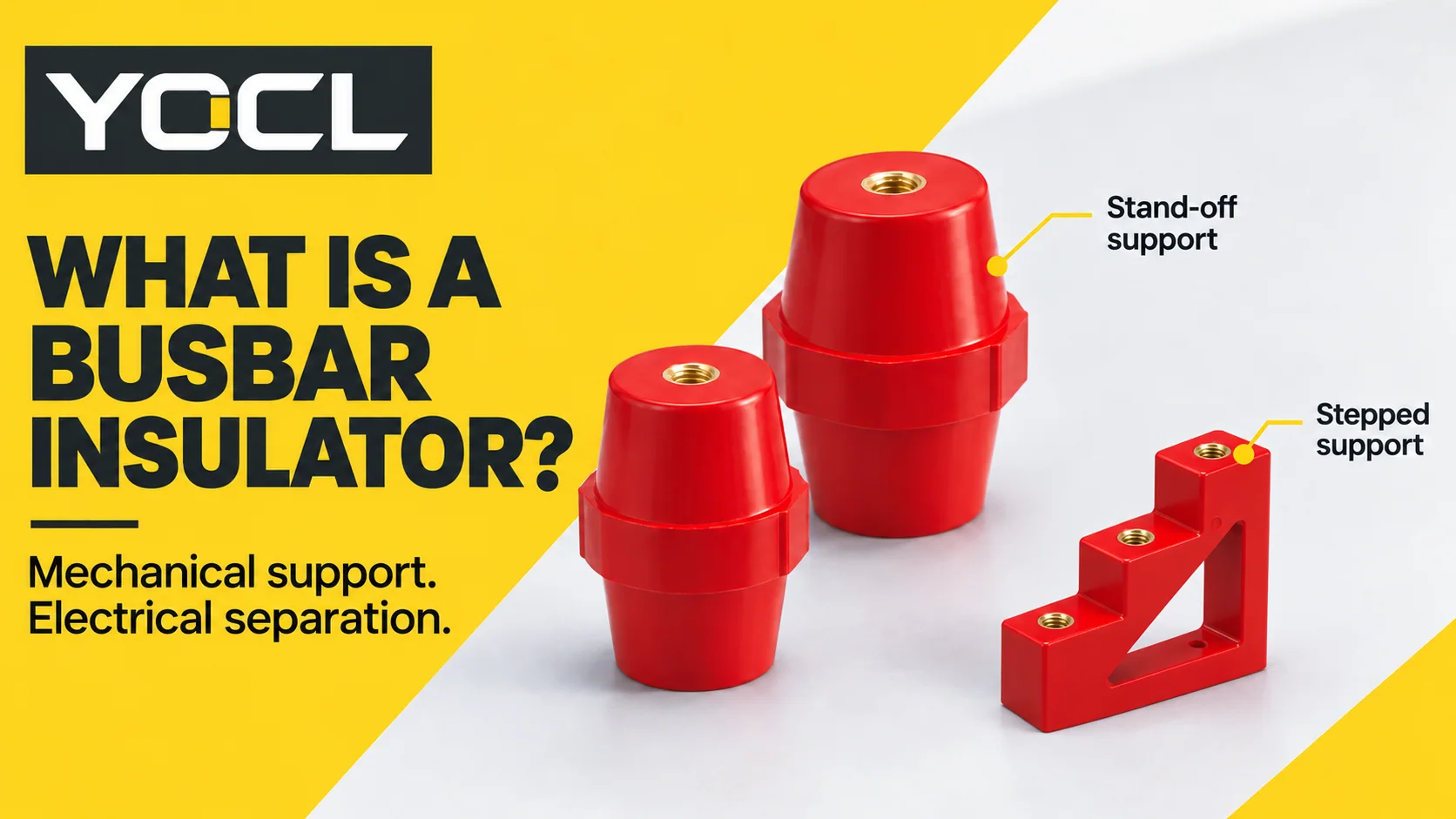
A busbar insulator is an insulating support used to fix a copper or aluminium busbar inside electrical equipment. It holds the conductor at its intended mounting position and separates it electrically from the frame or other conductive parts. Common versions include post-shaped stand-offs and shaped supports that hold several bars. The busbar itself carries and distributes electrical power within the equipment.
In a low-voltage switchboard, this small component has two connected responsibilities: carry the mechanical load and maintain insulating separation. A support that fits physically may still be unsuitable electrically; a component with an impressive dielectric test value may still be unsuitable for the installed mechanical load. YOCL’s SM support drawings show the insulating body and its separate fixing interfaces.
| Question | Short answer |
|---|---|
| Where is it used? | Between a busbar and its mounting structure, or within an arrangement that positions several conductors |
| Does it cover the live bar? | No. Supporting insulation and conductor covering perform different jobs |
| What matters besides voltage? | Mounting geometry, electrical distances, material properties, loads and the complete assembly arrangement |
How a busbar insulator works inside the assembly
Picture a copper bar above a metal mounting plate. The bar is attached to one face of an insulating support; the support is secured to the structure. The insulating body forms part of the separation between the conductive mounting interfaces. Metal inserts may provide threaded fixing points, but their arrangement must preserve the intended insulating path.
This creates a load path as well as an electrical boundary: bar → support → mounting structure. The support carries the relevant loads through its body and fixing interfaces. Weight is one load; connected cables and the way the bar is retained can introduce others.
During a short circuit, electromagnetic forces can move or bend the bars. The required support arrangement therefore depends on conductor geometry, phase spacing, the unsupported span and fault conditions. Changing a support or its position can change the behaviour of the assembly. The Copper Development Association and European Copper Institute explain these relationships in Copper for Busbars, section 4.4 “Mounting Arrangements”.
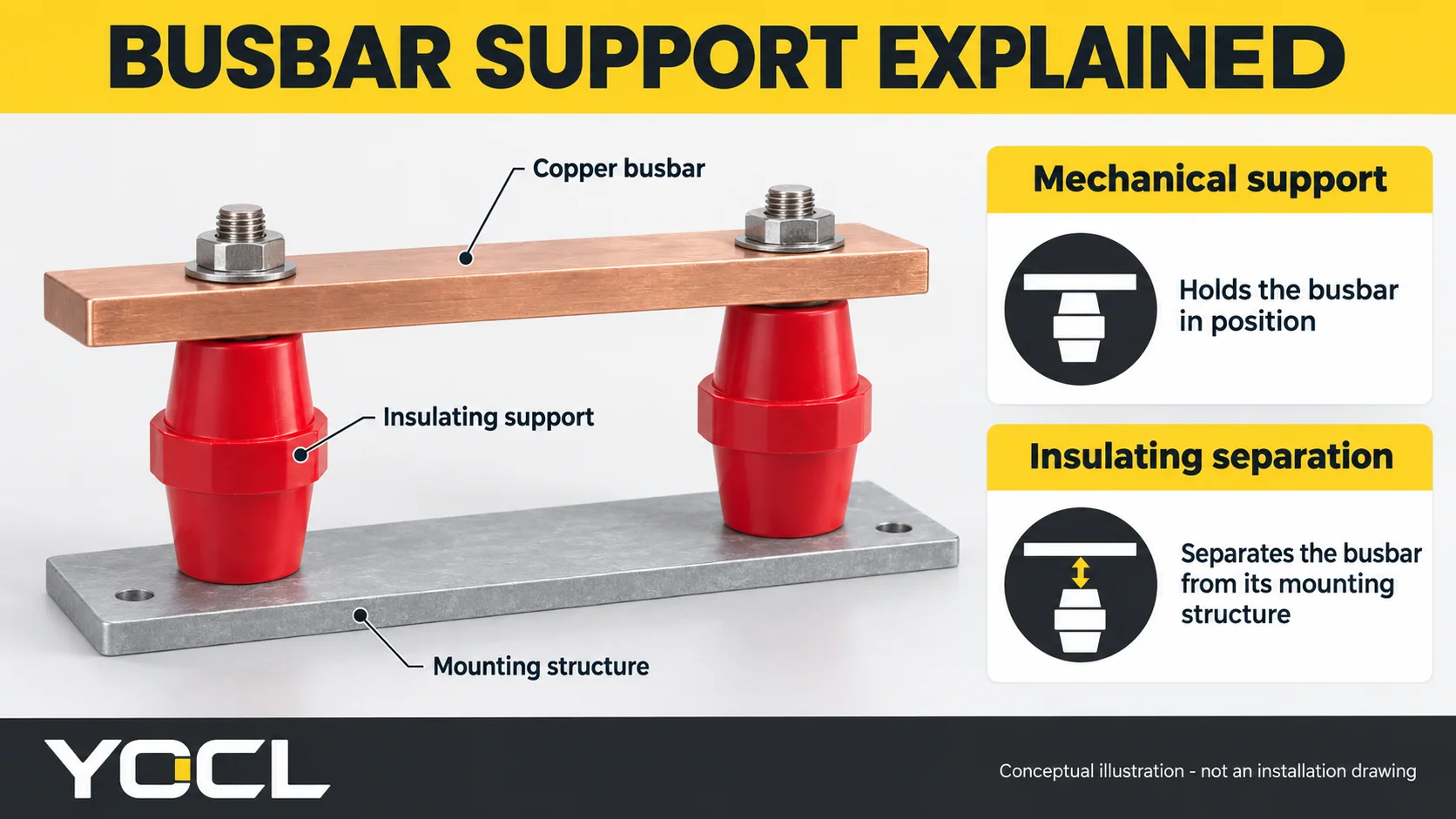
The support also helps retain the intended conductor positions. If a bar moves, the electrical separation from a neighbouring phase or metalwork may change. Mechanical integrity and insulation geometry should therefore be considered together.
A mounted bare busbar remains an exposed conductor. Required touch protection comes from the equipment’s enclosure, barriers or other protective arrangement; an insulating stand-off alone does not make the bar safe to touch.
Busbar insulator, support and covering: which part is which?
Catalogue terminology overlaps. Identify the function and interface before treating two names as interchangeable.
| Term | Main job | What to distinguish |
|---|---|---|
| Busbar insulator / support insulator | Support or locate the bar while providing insulating separation | A component with both electrical and mechanical duties |
| Stand-off insulator | Hold a conductor away from a mounting surface | A particular support construction, not the shape of every insulator |
| Busbar holder or clamp | Retain bars in a defined position | It may form part of an insulating support system; the name alone does not establish its material or rating |
| Busbar covering | Insulate the conductor’s surface using a sleeve, coating or moulded covering | Covering does not automatically provide the required mechanical support |
For example, adding heat shrink to a copper bar changes its covering. It does not establish the strength of the mounting supports or verify the complete layout. The coatings annex in Copper for Busbars, pages 103–105 distinguishes conductor coatings and sleeves as a separate subject.
Common busbar insulator types and their mounting arrangements
The shape is a clue to the interface. It is not a voltage classification or a guarantee of interchangeability.
| Construction | Arrangement it helps create | Main details to check |
|---|---|---|
| Post or stand-off | Individual fixing points between a bar and a base structure | Height, footprint, fixing faces, thread and insert depth |
| Cylindrical support | A compact round mounting interface in different diameter/height combinations | Body diameter, actual height option and thread configuration |
| Stepped support | Mounting positions at different levels within a bar layout | Step positions, hole centres, overall envelope and fixing access |
| Grooved or multi-bar support system | Several bars retained in defined positions with associated hardware | Bar number, section and orientation; retention parts and documented system configuration |
YOCL’s SM support insulators, MNS metric-thread cylindrical insulators and CT/CJ stepped supports illustrate the first three arrangements. Their drawings provide the model-specific dimensions that a photograph cannot establish.
For a multi-bar arrangement, inspect the complete system documentation. A holder, retaining screw and mounting rail may work together; comparing one loose component does not compare the whole arrangement.
What materials are busbar insulators made from?
Busbar supports are made from several insulating material families. The relevant comparison is between documented grades and constructions, because resin formulation, reinforcement, geometry and manufacturing process affect the finished component.
| Material family | Typical context to distinguish | Properties to compare for the application |
|---|---|---|
| Glass-fibre-reinforced thermoset moulding compounds | Bulk moulding compound (BMC) and sheet moulding compound (SMC) in electrical and switchgear applications | Compound grade, electrical properties, load capacity and temperature limits |
| Other organic-material post insulators | A broader support family that also includes indoor applications above 1 kV | Exact material, electrical duty, fixing arrangement and environmental scope |
| Ceramic or glass post insulators | A separate post-insulator family with applications above 1 kV | Model-specific mounting, electrical distances, mechanical duty and environment |
The European Alliance for SMC and BMC describes these compounds’ use in electrical and switchgear applications and their formulation-dependent properties. For the broader post-insulator families, the official scopes of IEC 60660 and IEC 60168 distinguish organic-material indoor supports from ceramic/glass supports in their stated higher-voltage applications. Those scopes do not classify every low-voltage busbar stand-off or make the families interchangeable.
A red body does not identify its compound grade. Likewise, a resin or compound name alone does not establish a working voltage, outdoor suitability or load capacity. Compare the exact material data and finished-part specification rather than assigning a universal winner to a material name.
Clearance and creepage: two different electrical paths
Clearance is the shortest distance through air between conductive parts. Creepage distance is the shortest distance along an insulating surface between conductive parts.
On a supported busbar, one relevant air path may run between the live bar or fastening hardware and the metal frame. A surface path may follow the support body between conductive interfaces. These paths are measured in the installed geometry; neither should be assumed to equal the catalogue height.
The conditions behind those distances differ:
| Condition | Why it matters |
|---|---|
| Working voltage | Helps determine the insulation duty under normal operation, including surface-distance requirements |
| Transient/impulse duty and overvoltage category | Affect the clearance needed for the specified surge environment |
| Pollution degree | Describes the contamination conditions relevant to insulation coordination; surface contamination can change electrical behaviour |
| Material tracking resistance | Helps classify how an insulating surface behaves under the applicable conditions; a material name alone is insufficient |
| Altitude | Requires consideration in air-clearance design; a layout suitable at one altitude is not automatically suitable at another |
The SIST-hosted preview of IEC TR 60664-2-1:2011, sections 1 and 3 explains the terminology and general insulation-coordination factors. UL’s CTI explanation describes material tracking classification. For current requirements, use the applicable edition of IEC 60664-1, whose published scope includes altitude considerations.
Ribs and shaped surfaces can lengthen a surface path, but extra ribs do not establish the required air clearance. Bolts, brackets, adjacent bars and the enclosure still determine the shortest paths in the finished arrangement. The next step is to evaluate the actual drawing against the applicable equipment requirements, rather than choose a support by height alone.
How to read a busbar insulator datasheet
Read the document in two passes: first establish what physically fits, then establish what electrical, mechanical and environmental duty the documented configuration supports.
1. Read the geometry and fastening interface
Check the overall height, body envelope, fixing centres, thread designation and insert depth. Those fields determine how the part relates to the bar, base and fasteners.
YOCL’s current SM catalogue provides a useful example:
| Published dimension | SM-25S | SM-25 |
|---|---|---|
| Overall height | 25 mm | 25 mm |
| Central band height | 6 mm | 10 mm |
| Body diameter marked on the drawing | 15 mm | 23 mm |
| Overall plan span as shown | 19 mm | 30 mm |
| Nominal thread diameter | 6 mm | 6 mm |
| Thread depth | 8 mm | 9 mm |
Both are 25 mm high, yet their bodies and fastening depths differ. Height therefore cannot identify an equivalent replacement. These are transcribed catalogue dimensions, not measured test results. Use the SM model drawings to confirm the complete interface, including thread details that a nominal diameter does not specify.
The same check matters when switching thread systems. YOCL lists MNS imperial-thread supports separately; a similar body shape is not evidence that metric and imperial hardware will mate.
2. Separate operating duty from test results
Electrical fields answer different questions. A nominal or operating voltage describes the stated application duty; a dielectric withstand value describes performance under the stated test conditions.
For a concrete reading example, the YOCL SM catalogue lists 6 kV in the “Voltage withstand” field for both SM-25S and SM-25. That is a catalogue declaration of withstand performance, not evidence of a 6 kV continuous operating rating.
The public table does not specify a corresponding continuous operating voltage, test duration, waveform or AC/DC application for these entries. Obtain the model’s applicable rating and test documentation before using that field for a design decision. The IEC application-guide preview, section 3.29 likewise defines withstand performance by specified conditions; it does not establish YOCL’s test result or product rating.
3. Interpret mechanical and temperature fields in context
| Field | What to establish before using it |
|---|---|
| Tensile, bending or compression strength | Load direction, fixing arrangement, test conditions and permissible application load |
| Torque strength | Whether it is a strength-test result; obtain a separate installation tightening instruction where required |
| Temperature limit | Whether it describes the material, component or operating environment, and how it relates to the actual assembly |
| Flammability classification | Exact material, test scope and conditions; it does not substitute for electrical or assembly verification |
A pulling-test result cannot be assumed to cover a sideways bending load. Similarly, a catalogue torque-strength field is not an instruction to tighten every screw to that number. Use the documented mounting instructions for the chosen hardware and component.
If a material is classified UL 94 V-0, that is a plastics flammability classification under defined test conditions. It does not provide an operating-voltage rating or certify the finished switchboard. UL’s plastics combustion-testing explanation describes this material-test scope.
Why the complete busbar assembly still needs verification
There are three levels to distinguish:
- Component: the individual support’s construction and documented properties.
- Support arrangement: bars, supports, fasteners, spans and mounting members working together.
- Complete assembly: that arrangement within equipment, including its insulation, temperature-rise and fault-withstand requirements.
For example, lengthening an unsupported bar span changes the mechanical arrangement even if the support model stays the same. Increasing conductor current can change the thermal conditions around the supports. Neither change is resolved by quoting the support’s dielectric test voltage.
| Reference | What it helps address | What citing it does not prove |
|---|---|---|
| IEC 60664-1 | Insulation coordination: clearance, creepage and solid-insulation criteria within its scope | Certification of an individual support or suitability for every voltage/environment |
| IEC 61439 series | Low-voltage switchgear and controlgear assembly requirements and verification | That any collection of individually specified components forms a compliant assembly |
| Exact model/system documentation | Dimensions, properties, mounting limits and permitted configurations | Performance outside the documented conditions |
IEC 61439-1:2020 establishes general rules for low-voltage assemblies. Conformity also depends on the relevant part of the series from Part 2 onwards. A support datasheet supplies design inputs; it does not replace the required assembly verification.
Find the right next document for your question
Use the question below to decide what to investigate next. The aim is to move from recognising the component to obtaining the information needed for the actual equipment.
| Your next question | Start with | Information to have ready |
|---|---|---|
| Which support shape could fit this layout? | The YOCL support-family and model range and its dimensional drawings | Bar dimensions, orientation, mounting points and available envelope |
| Are these two parts interchangeable? | Both exact model drawings and the equipment’s permitted replacement specification | All fixing dimensions, thread details, electrical duty and relevant mechanical requirements |
| Is the insulation distance adequate? | Insulation-coordination guidance and the applicable equipment documentation | Conductive-part geometry, voltage/impulse duty, environment and altitude |
| What support spacing will withstand a fault? | Verified busbar-system documentation or an engineering assessment of the complete arrangement | Bar layout, span, phase spacing, fault duty and mounting structure |
| Is a damaged support suitable for continued use? | The equipment manufacturer’s inspection and replacement instructions | Equipment identity, damage location, photographs and relevant service/fault history |
Visible damage or unexpected contamination is a reason to consult the equipment’s inspection and replacement instructions before deciding on continued use. Access, cleaning, testing and replacement must follow the applicable isolation and safety procedures and be handled by qualified personnel. For U.S. workplace electrical work, OSHA 1910.333 sets requirements for deenergizing exposed live parts and verifying the deenergized condition, subject to its stated exceptions. It is a work-practice rule, not a busbar-support inspection specification. Do not copy a test voltage or tightening routine from another system.
For a model enquiry, provide the drawing or existing-part reference, quantity, mounting geometry, thread requirements and known operating conditions. That gives the supplier a defined interface to check; a request for “a red 25 mm insulator” leaves essential information unresolved.
Frequently asked questions
Does a busbar insulator have a current rating?
The support is intended to provide insulation and mechanical support, rather than carry the busbar’s load current. A documented support system may specify a busbar/current configuration, but that is a system rating. The temperature around the support still matters. Determine current capacity through the conductor and complete assembly design, not from support height or dielectric withstand.
Can the same busbar insulator be used for AC and DC?
Only when the exact model and installed arrangement are documented for the required duty. An AC rating or unspecified catalogue voltage is not automatically a DC rating. IEC 60664-1 includes both within its defined scope, but that does not establish the AC/DC suitability of a particular support.
Is a taller busbar insulator always a better choice?
No. Height affects the layout, but the relevant electrical paths depend on all nearby conductive parts. A taller support also changes the mounting arrangement and space required. Compare the complete geometry and documented electrical/mechanical requirements rather than treating height as a safety ranking.
Related reading: busbar insulator height and mounting dimensions.