
Perfil y profundidad
Comprobar el plano del equipo para TS35 35 × 7.5 mm, TS35 35 × 15 mm, G32 o TS15. Confirmar la sección transversal completa y el espacio necesario para instalar y liberar el dispositivo.
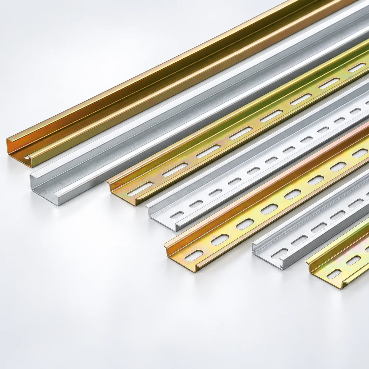
DIN rieles para paneles eléctricos y armarios de control. Compare 35 mm rieles de carril superior, 32 mm de perfil G y 15 mm minirrieles en acero y aluminio, y luego especifique la sección, las ranuras de montaje y la longitud que coincidan con su equipo.
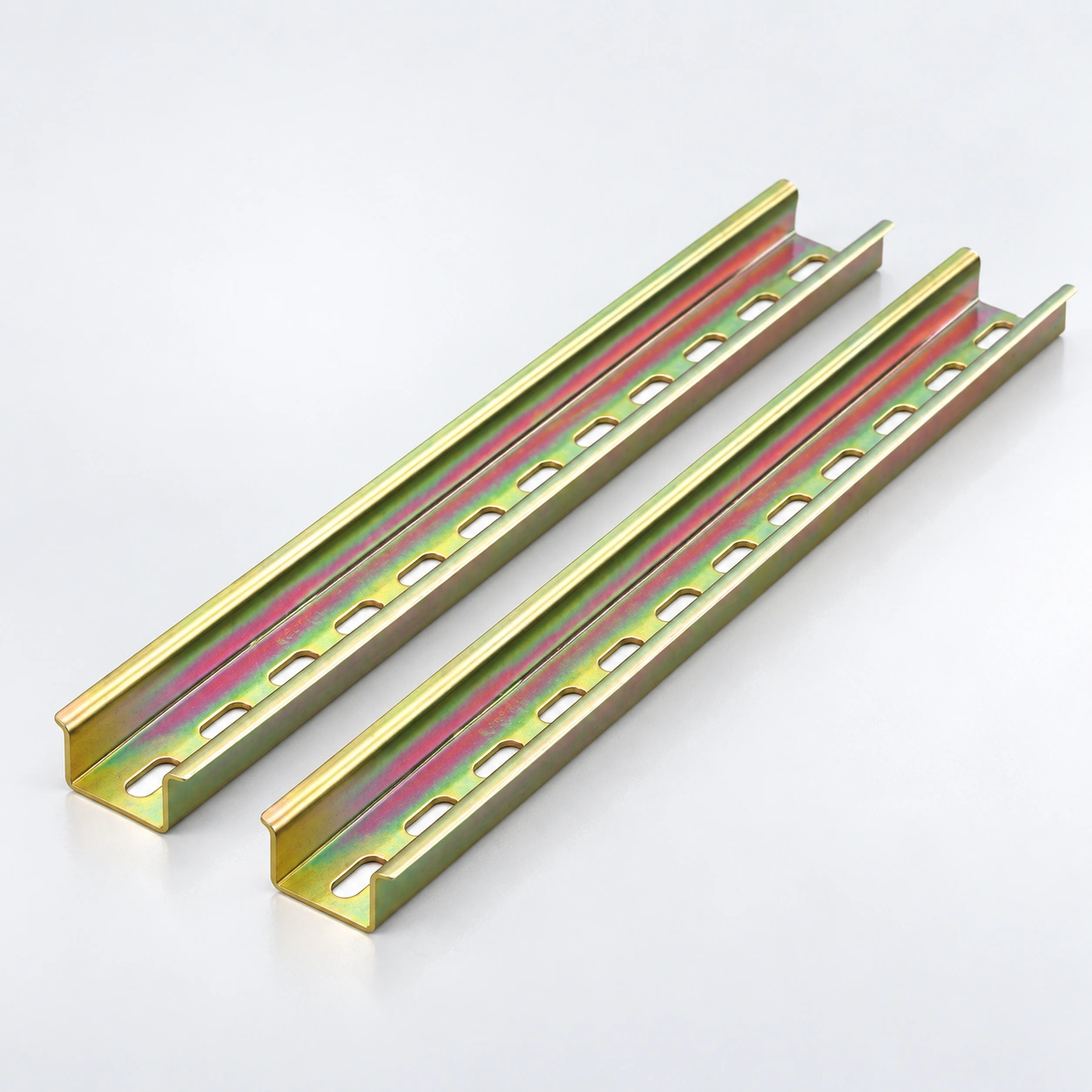
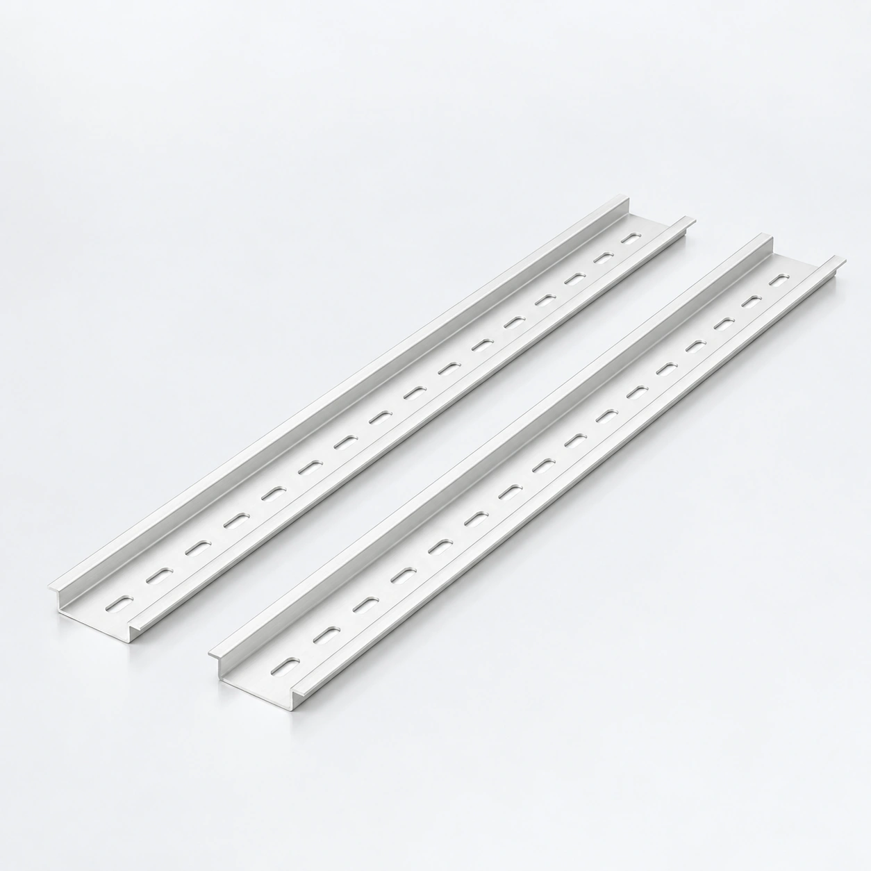
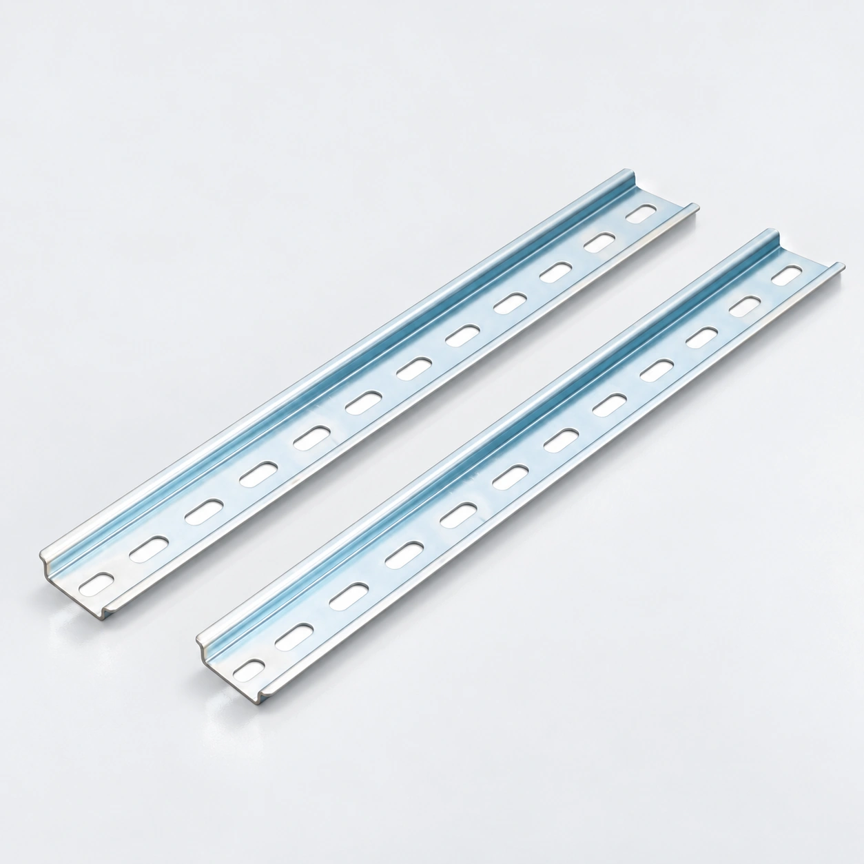
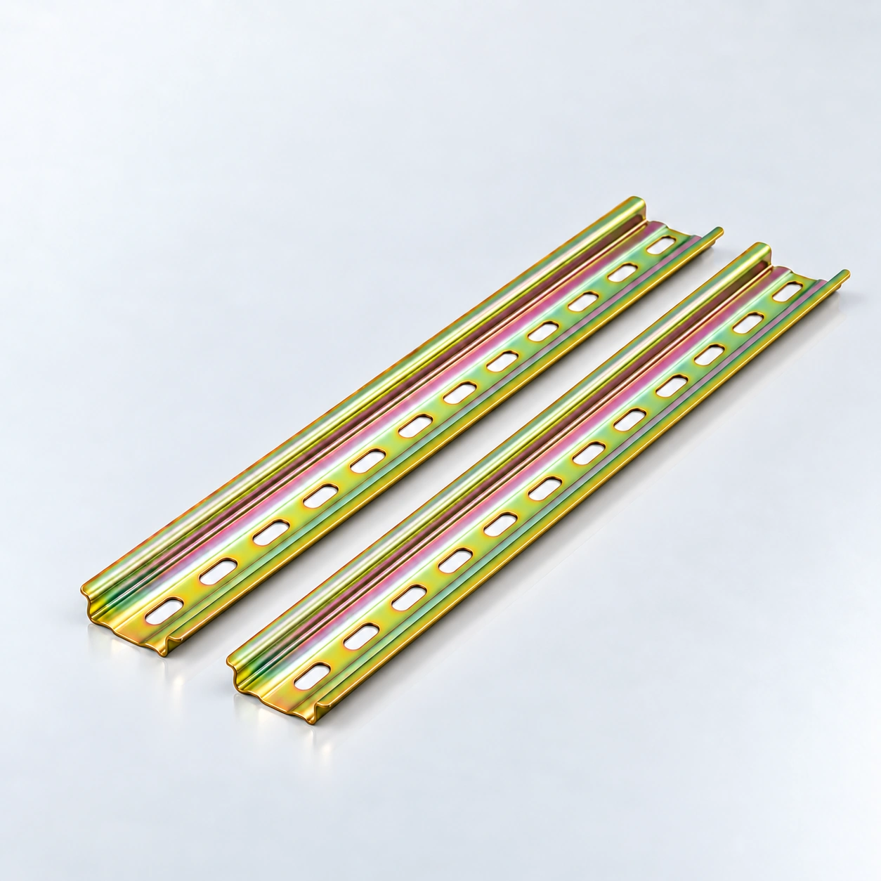
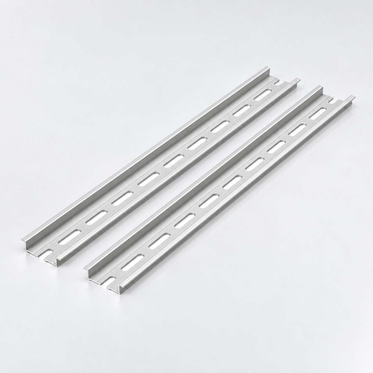
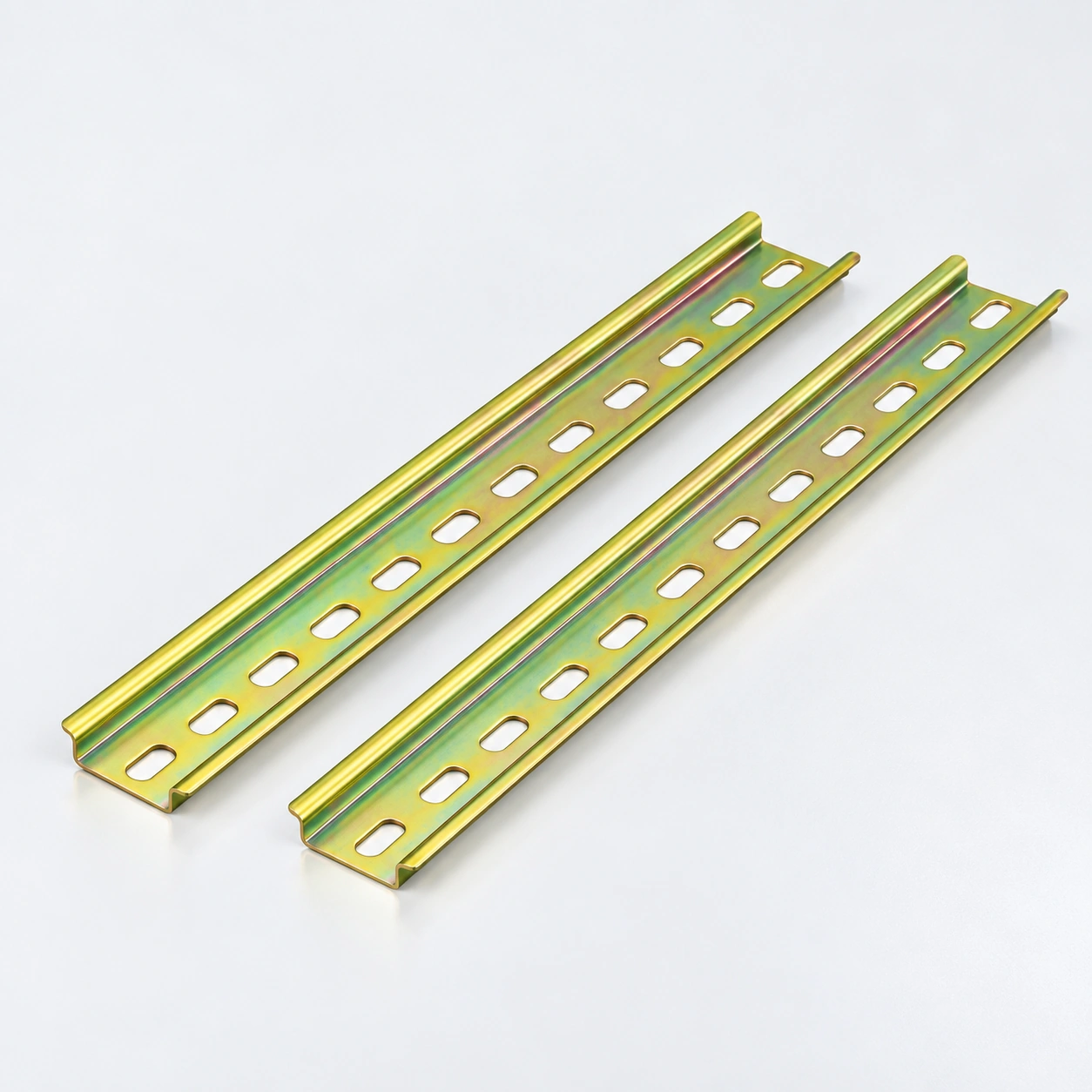
| Construcción | Enfoque de selección | Referencia de serie |
|---|---|---|
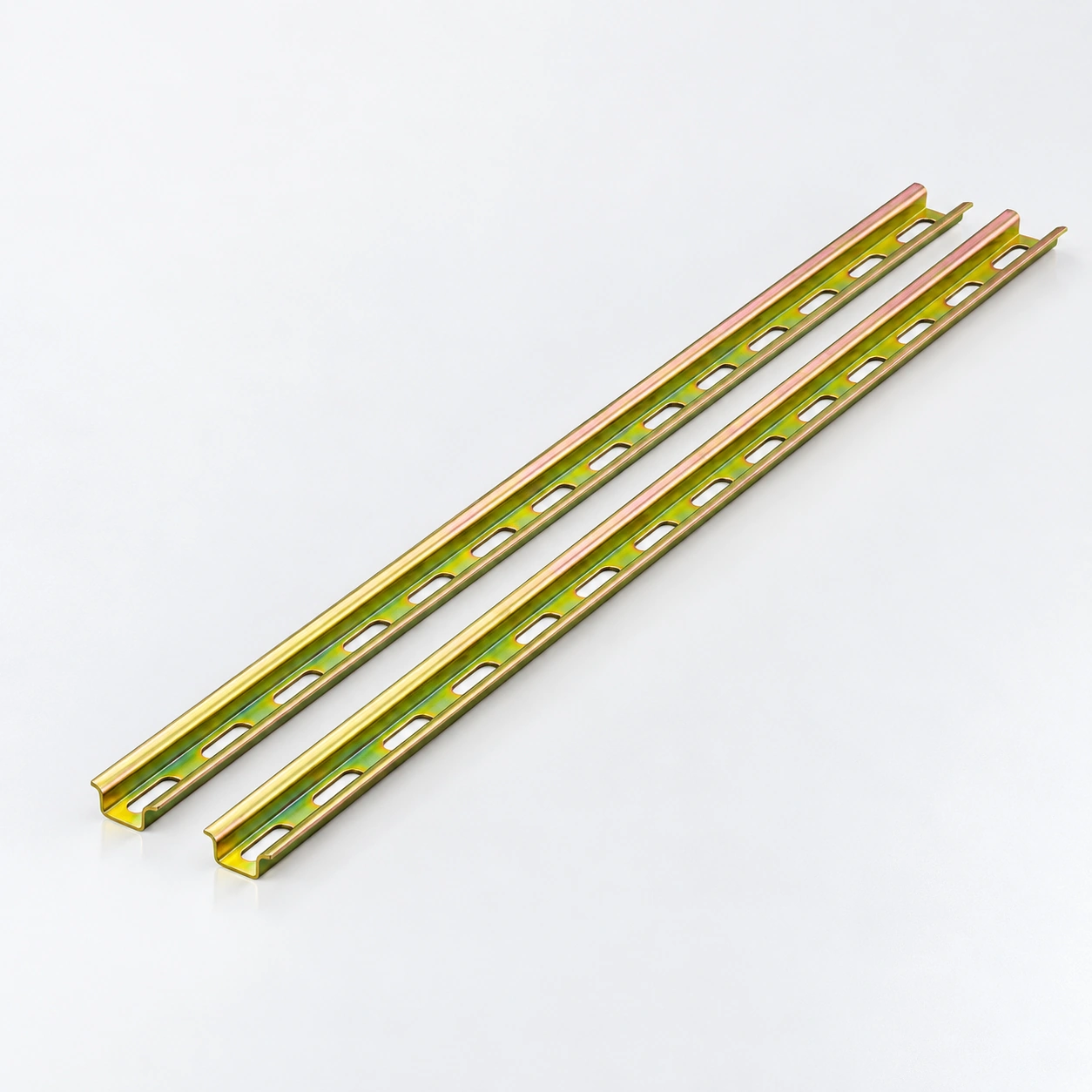
| 35 × 7.5 mm · Acero ranurado | Las configuraciones estándar y de ranura larga ofrecen 0.9, 1.0 o 1.2 mm de grosor y 0.5, 1 o 2 m de longitud. Los tamaños de las ranuras son 6.2 × 15 o 5.2 × 25 mm respectivamente. La serie también incluye configuraciones en blanco y azul, convencionales y acanaladas; seleccione una fila de especificaciones completa. | TS35 · Dependiente de la configuración |
| 35 × 7.5 mm · Acero acanalado | 0.8 mm espesor nominal con ranuras oblongas 5.2 × 15 mm. Las longitudes estándar son 1 m y 2 m. Haga coincidir la sección acanalada con el requisito de montaje del equipo. | TS35 · sección acanalada |
| 35 × 7.5 mm · Acero blanco azulado | 1.0 mm espesor nominal, ranuras 6.2 × 15 mm y longitudes de 1 m o 2 m. Blanco azulado describe la apariencia; confirme el tratamiento superficial requerido por separado. | TS35 · apariencia blanco azulado |
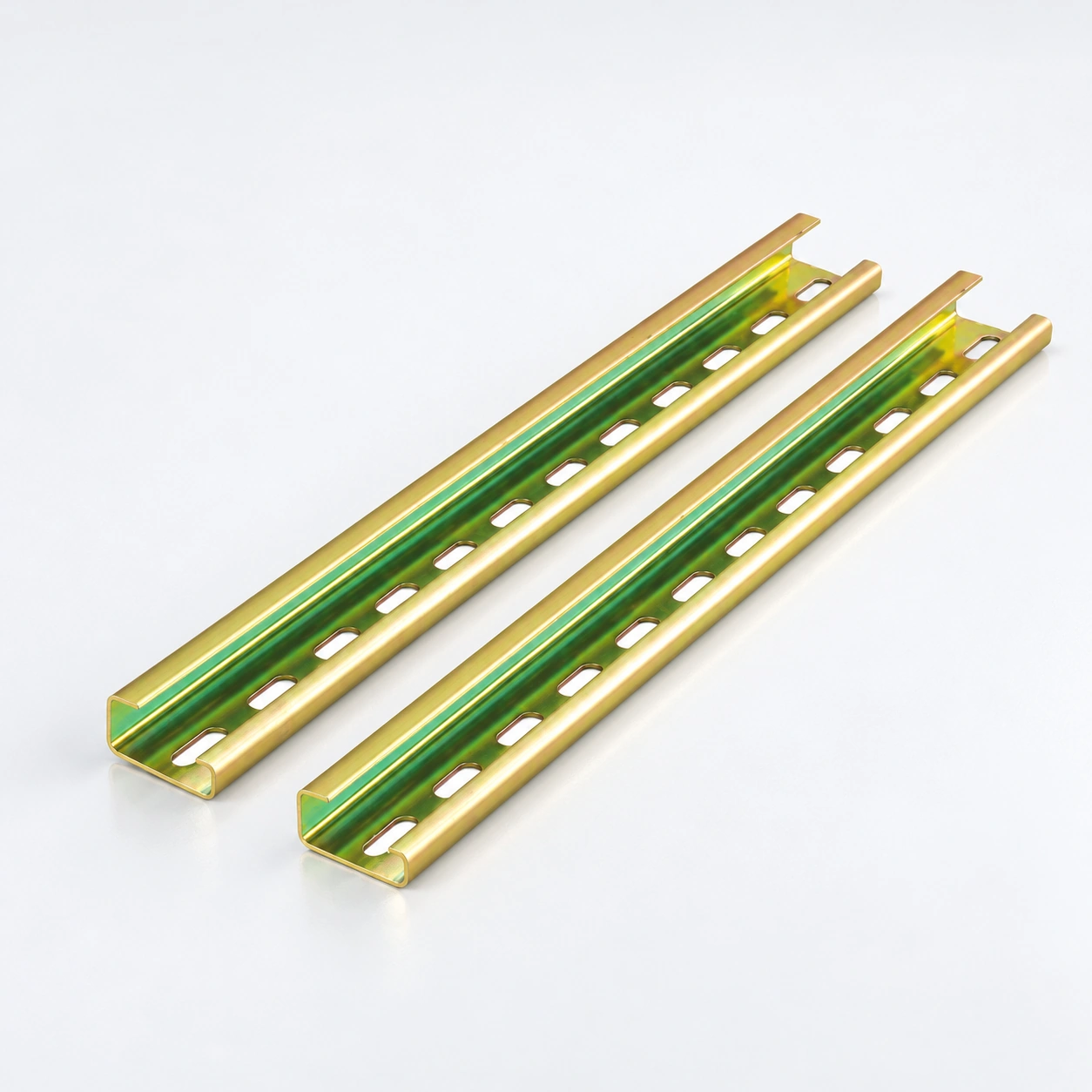
| 35 × 15 mm · Acero ranurado | 15 mm profundidad de perfil, 1.5 mm espesor nominal y ranuras 6.2 × 15 mm. Las longitudes estándar son 1 m y 2 m. Compruebe la sección más profunda con la separación del dispositivo y los requisitos de los pies de montaje. | TS35 · 15 mm de profundidad |
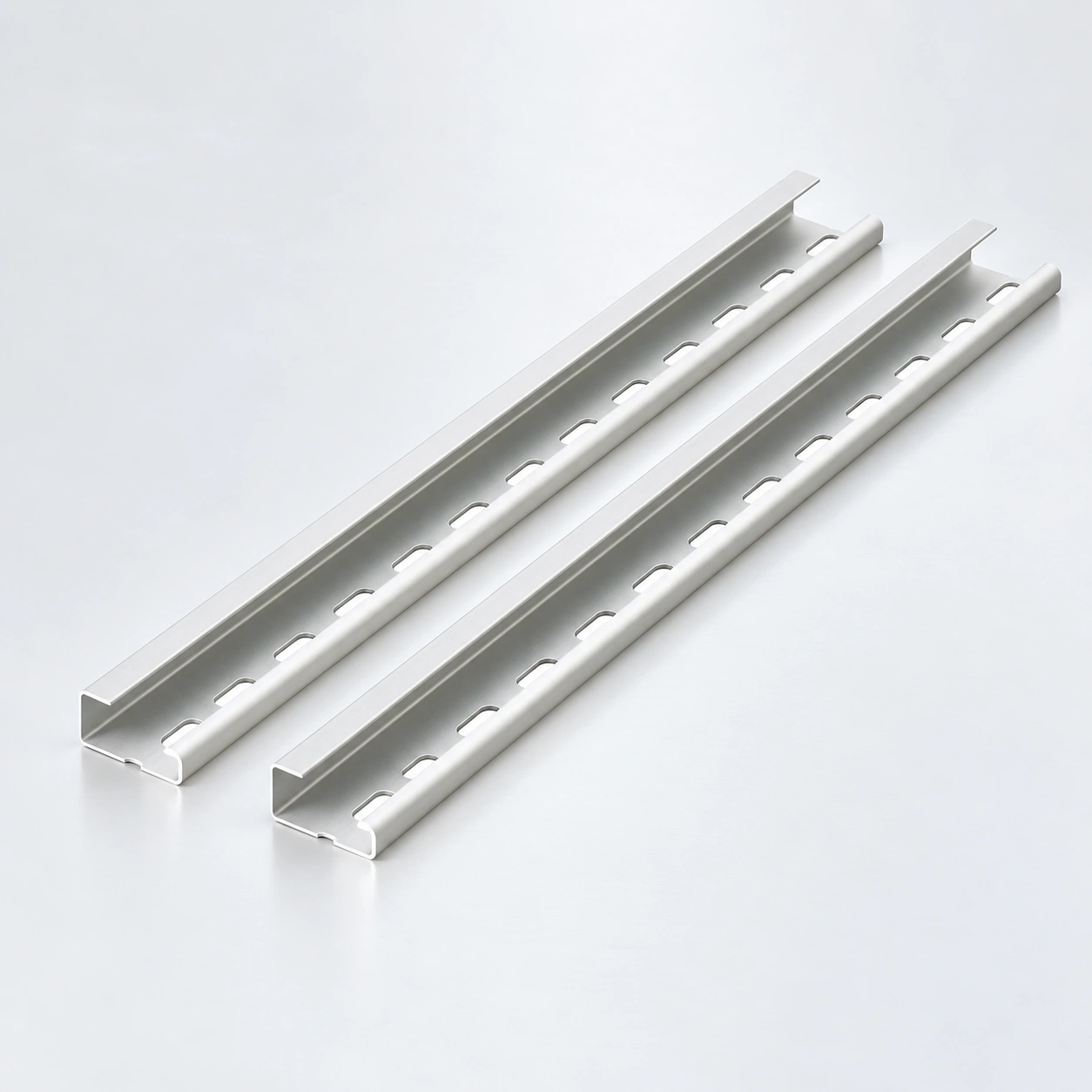
| 35 × 7.5 mm · Aluminio ranurado | Las 4.2 × 12 mm ranuras se combinan con un grosor de 0.7, 0.9 o 1.1 mm. La configuración de ranura larga 4.8 × 25 mm utiliza un grosor de 1.1 mm. Ambas configuraciones indican longitudes de 1 m y 2 m. | TS35 · Aluminio |
| 32 mm · Perfil G de acero | Proyecciones de brida asimétricas 15/9 mm, grosor de 1.2 mm y ranuras de 6.2 × 15 mm. Las longitudes estándar son 1 m y 2 m. Requiere un pie de montaje de perfil G a juego. | G32 / TS32 · Acero |
| 32 mm · Perfil G de aluminio | Proyecciones de brida asimétricas 15/9 mm, grosor de 1.2 mm y ranuras de 6.2 × 15 mm. La longitud estándar publicada es de 1 m, a diferencia de la versión de acero. | G32 / TS32 · aluminio |
| 15 × 5.5 mm · Mini acero | Perfil compacto de carril con 0.9 mm de grosor y 4.2 × 12 mm ranuras. Las longitudes estándar son 1 m y 2 m. Seleccionar solo para dispositivos especificados para esta sección de montaje más pequeña. | TS15 · mini carril |
El ancho del carril por sí solo no establece la compatibilidad. Mantener juntos el perfil, el material, el grosor y los detalles de fijación al comparar opciones.
Comprobar el plano del equipo para TS35 35 × 7.5 mm, TS35 35 × 15 mm, G32 o TS15. Confirmar la sección transversal completa y el espacio necesario para instalar y liberar el dispositivo.
Specify steel or aluminium, nominal thickness and required finish. Request project-specific corrosion or material documentation where needed; appearance is not proof of a coating specification.
Match slot width and length to the mounting arrangement. Slot size does not establish hole pitch. Supply the fixing drawing, fastener requirements and support spacing for review.
Choose a listed standard length for the selected configuration. Account for end stops, wiring access and enclosure clearances. Send cut-length or hole-layout requests for feasibility review.
Send the rail profile, material, thickness, slot dimensions, length and quantities, plus the device mounting reference and panel drawing.
Prepara una consultaAcuerde la especificación y la evidencia requerida antes de realizar su pedido.
Explorar fabricaciónList each rail profile, material, nominal thickness and quantity. Identify ribbed, blue-white or other configuration-specific requirements.
Provide slot dimensions, required hole pattern, panel fixing positions and support layout. Distinguish slot opening size from spacing.
Specify standard length or requested cut length, quantity per length and any edge or end-preparation requirements. Confirm non-standard work in the quotation.
State required drawings, material or finish documentation, labels, bundle quantities and destination. Agree sample acceptance criteria before ordering.
OEM Y EMBALAJE
Build your din rails order around the selected models, identification and supply requirements.
List each rail profile, material, nominal thickness and quantity. Identify ribbed, blue-white or other configuration-specific requirements.
Proporcione números de pieza, arte de etiquetas y cualquier información de lote o trazabilidad requerida para el pedido.
Especifique las cantidades por modelo, los paquetes individuales, las cajas exteriores y el destino de entrega.
DIN rail provides a mounting interface for compatible electrical devices in panels and cabinets. Select the rail using the device mounting-foot specification, the panel layout and the complete rail section.
Both listed profiles have a 35 mm width, but their depths differ. The published 35 × 15 mm steel rail uses 1.5 mm nominal thickness; the 7.5 mm ranges have configuration-specific thicknesses. Check device fit and enclosure clearance rather than assuming interchangeability.
Not by width alone. G32 has an asymmetric G-profile with 15/9 mm flange projections in this range. TS35 uses a top hat section. The mounted device must support the selected interface.
Lengths depend on the product. Most listed configurations offer 1 m and 2 m. The 35 × 7.5 mm steel standard-slot and long-slot configurations also list 0.5 m; the aluminium G32 rail lists 1 m. Use the length in the exact configuration row.
Do not assume so. Match the mounting geometry, thickness, fixing arrangement and project material requirements. The published options include different slot sizes and length choices.
No corrosion rating is established by that appearance description. Specify the required surface treatment and ask for supporting documentation for the quoted product.
No. This range provides mechanical mounting profiles. Comb busbars provide electrical connections between compatible devices. Select each component for its own function.
Send the cross-section, cut-length schedule, hole layout and quantities for review. Availability, tolerances, preparation, samples and commercial terms must be confirmed for the requested configuration.
Send the rail profile, material, thickness, slot dimensions, length and quantities, plus the device mounting reference and panel drawing. Include the exact model quantities, delivery destination and required documentation.
Envíe sus números de pieza, el diseño de la etiqueta, las cantidades de embalaje y los requisitos de envío. Se confirman la viabilidad, los requisitos de muestra, las cantidades mínimas y el plazo de entrega para los modelos solicitados.