
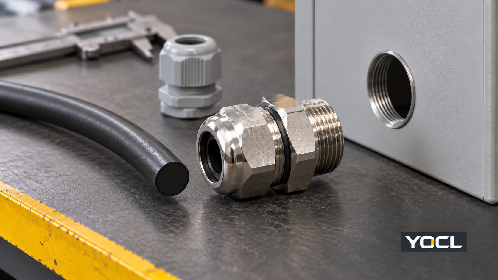
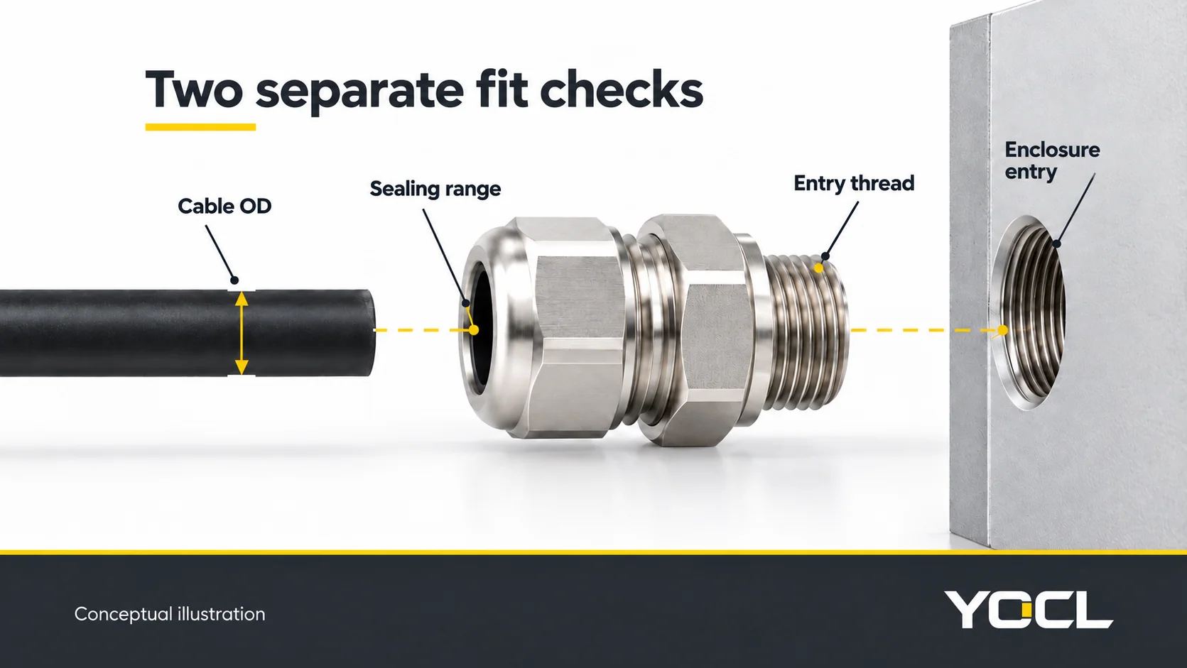
Elija un prensaestopas comprobando dos interfaces separadas: el cable debe ajustarse al rango de sellado del modelo exacto y la rosca de montaje del prensaestopas debe ajustarse a la entrada de la carcasa. Luego, verifique la construcción del cable, los materiales, las condiciones de exposición y los accesorios necesarios. M20 describe una rosca de entrada; no significa que el prensaestopas acepte un cable 20 mm.
Para los fabricantes de paneles y compradores, el resultado útil es una especificación que un proveedor puede verificar con un número de pieza exacto. Comience con la hoja de datos del cable y el dibujo de la carcasa, revise las comprobaciones siguientes y mantenga cualquier evidencia faltante abierta para su confirmación.
Puntos clave
- Compruebe el rango de tolerancia del diámetro exterior completo del cable, no solo su diámetro nominal o el tamaño del conductor.
- La clasificación IP de un prensaestopas no establece la protección del conjunto completo de entrada de cable.
- La terminación de armadura, el contacto de pantalla EMC y la idoneidad para áreas peligrosas requieren sus propios diseños y documentación verificados.
1. Recopilar las entradas del cable y la carcasa
Una solicitud de una “M20 prensaestopas estanca” deja al proveedor adivinando sobre el cable, la disposición de montaje y la exposición. Registre estas entradas antes de comparar modelos:
| Entrada | Qué registrar | Lo que debe coincidir la prensaestopas propuesta |
|---|---|---|
| Dimensiones del cable | Número de pieza del cable, diámetro exterior mínimo y máximo, material de la cubierta | Rango de sellado/sujeción del cable publicado y compatibilidad de la cubierta |
| Construcción del cable | Redondo o no redondo; sin blindaje, apantallado o blindado | Geometría de sellado adecuada y función de terminación requerida |
| Terminación de cable | Cable desnudo o conector montado; dimensiones del conector si están presentes | Disposición de entrada que admita el conector y selle el cable final |
| Entrada de la carcasa | Designación completa de la rosca o dibujo de agujero pasante | Estándar de rosca coincidente, tamaño y paso, o ajuste de agujero especificado |
| Espacio de montaje | Grosor de la placa, material de la carcasa, herramienta disponible y espacio libre interno | Longitud de rosca de montaje adecuada y acceso físico |
| Entorno | Rango de temperatura, luz solar, líquidos, productos químicos y carga mecánica | Idoneidad documentada del cuerpo, el sello y la entrada ensamblada |
| Requisitos del proyecto | Mercado objetivo, requisitos del equipo y cualquier clasificación de ubicación peligrosa | Exact-part documentation and application review where required |
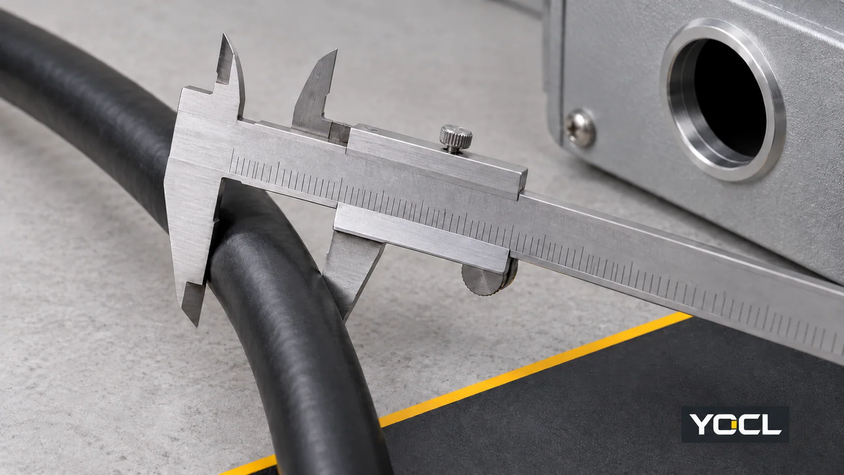
Use a caliper to check the outside of a cable sample at the intended sealing location without compressing the jacket. A sample measurement helps identify the cable; the cable manufacturer’s dimensional limits remain important when selecting for production batches. Conductor cross-section in mm², AWG and core count do not specify the finished cable diameter.
2. Match the entire cable diameter range
Find the sealing or clamping range for the exact gland and insert, rather than using a generic thread-size chart. For a round cable, the basic dimensional screen is:
Mínimo de prensaestopas ≤ mínimo de cable, y máximo de cable ≤ máximo de prensaestopas.
Both comparisons must pass. If the cable tolerance is unknown, the fit remains unconfirmed. Do not invent an extra clearance allowance or assume that tightening harder compensates for an out-of-range cable. Confirm any differences between the manufacturer’s sealing and retention ranges before approval.
Worked example: two M20 glands, different cable ranges
The following published LAPP products both use M20 × 1.5 entries, but accept different cable diameters:
| Named manufacturer example | Designación de entrada | Published clamping range | Screen for an assumed 12.2–12.8 mm cable |
|---|---|---|---|
| LAPP SKINTOP ST-M, article 53111020 | M20 × 1.5 | 6–13 mm | Within the stated range: both endpoints fit |
| LAPP SKINTOP ST-M ISO, article 53017030 | M20 × 1.5 | 5–12 mm | Outside the stated range: the cable exceeds 12 mm |
The cable dimensions are hypothetical. The gland ranges are named third-party product examples, not YOCL specifications or a recommendation to buy either product. The first candidate passes this diameter check only; its mounting geometry, material, retention and sealing evidence still need verification.
An oversized gland can also fail: if a cable is smaller than the published minimum, the seal may not provide its documented performance. Choose another documented range or a manufacturer-specified reducing insert. A larger mounting thread is useful only if the cable-side fit and enclosure-side fit also work.
3. Match the enclosure entry independently
Identify the entry from the enclosure drawing or verified thread measurements. Similar-looking sizes do not establish compatibility.
| Entry family | Identification example | Selection check |
|---|---|---|
| Métrica | M20 × 1.5 | Match nominal thread diameter and pitch; distinguish the threaded entry from a clearance hole |
| PG | PG13.5 | Match the actual PG designation; a nearby metric size is not a direct replacement |
| NPT | 1/2-inch NPT | Match the tapered thread designation; its nominal inch size is not the cable diameter |
LAPP’s technical overview of cable-gland threads distinguishes metric, PG and tapered NPT entries. Metric and PG entries use parallel threads, but their thread forms and dimensions differ. Use a compatible adapter only when the equipment and gland documentation permit the resulting arrangement.
Check the mounting and accessory stack
For a clearance hole, establish the required hole dimensions and fixing arrangement from the selected product drawing. For a tapped entry, confirm the mating thread and engagement requirements. In either case, check:
- Plate thickness and any sealing washer, bonding accessory or other specified stack components.
- Available mounting-thread length and space for a locknut where required.
- Gland protrusion, spacing between adjacent entries and access for the specified tightening tools.
- Cable routing space so the entry is not forced sideways by an unsuitable bend or unsupported load.
Specify fixing, entry sealing and bonding accessories by function. A locknut secures the gland; an entry seal addresses the enclosure joint; a bonding accessory serves an electrical connection when required. Do not assume one component performs all three jobs. Compare the relevant accesorios para prensaestopas against the proposed assembly drawing.
4. Select the function the cable actually needs
A standard single-hole gland is a candidate for one round, unarmoured cable. Other cable constructions add requirements that outside diameter alone cannot resolve.
Cable blindado
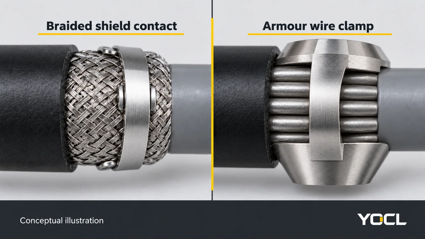
Record the armour type and material, wire or tape dimensions, overall diameter and inner bedding diameter where relevant. A gland that fits the outer jacket may still have the wrong armour clamping range or inner seal.
CMP’s gland sizing tables list bedding, overall cable and armour ranges separately. Use those distinct checks when evaluating armoured cable glands. Where the armour forms part of the protective bonding path, obtain the project’s electrical requirements and the corresponding gland/accessory evidence; mechanical fit alone does not approve that path.
Screened cable and EMC
State whether the screen must terminate at the entry, the screen construction and the equipment’s required connection arrangement. Look for a documented contact mechanism and a compatible connection to the enclosure.
For example, CMP’s TSZ EMC gland documents circumferential contact with the cable screen. This illustrates a purposeful shield-contact function; an ordinary metal body does not establish equivalent performance. Evaluate Prensaestopas para EMC using the exact product instructions and the equipment’s EMC design.
Pre-terminated, multiple or non-round cables
For a fitted connector, check both connector passage and the final cable seal. Enlarging a conventional gland until the connector passes can leave the cable too small for its sealing range. A purpose-designed split entry may solve that geometry; icotek’s QVT-CLICK is one documented example for pre-terminated cables.
For multiple cables, select a documented multi-hole insert with a suitable range for each cable and an approved method of closing unused holes. Do not assume a single round seal can seal a bundle. Flat or oval cables similarly need a seal intended for that profile. Verify the rating of the actual entry configuration rather than borrowing a rating from another design.
Hazardous locations
Route the selection to a competent hazardous-area reviewer. Supply the location classification, equipment certificate and instructions, cable construction, required protection concept and operating conditions. Request exact-model certificates and any conditions of use. An “Ex” label, metal construction or IP68 claim cannot approve the application.
IEC 60079-14:2024 addresses Ex installation design, equipment selection, installation and initial inspection, including documentation and competency requirements. Apply the edition and national requirements specified for the project. Barrier-gland decisions require that application review; there is no universal answer based on cable diameter alone.
5. Translate exposure into material and sealing requirements
Comparar nylon cable glands y metal cable glands against the declared exposure. Material names are a starting point, not a complete specification.
Check the body material or metal grade, surface finish, seal compound and cable jacket together. Outdoor selection needs evidence for sunlight exposure. Chemical selection needs the actual chemical, concentration, temperature and contact conditions. Thermal selection needs the documented range for the complete configuration, including the seal.
HUMMEL’s material guide treats body materials and sealing materials separately and distinguishes stainless-steel grades. Do not extend the resistance of one compound or grade to every “nylon,” “brass” or “stainless” gland. Also check compatibility with the enclosure material and the specified corrosion-protection measures.
Specify the water exposure behind the IP rating
Replace “waterproof” with a description the supplier can evaluate:
| Exposure to specify | Relevant rating evidence to check | Acceptance boundary |
|---|---|---|
| Powerful water jets | IP66 | Jet protection does not establish immersion suitability |
| Inmersión temporal | IP67 | Confirm the stated test and installation conditions |
| Sustained or specified immersion | IP68 | Obtain the declared depth or pressure, duration and tested configuration |
| Hot, high-pressure cleaning | Appropriate documented washdown rating and test conditions | Do not infer suitability from an IP68 claim alone |
CMP’s ingress-protection guide explains these jet and immersion categories and the need to specify IP68 conditions. IP68 is not a promise of unlimited immersion under every condition. Water-jet and immersion tests are distinct, as Schneider Electric explains in its IP-rating FAQ; request both where both exposures apply.
Check the cable seal y the gland-to-enclosure joint, including any adapter. The rating of a gland and the rating of an enclosure do not, by themselves, verify that joint or the completed assembly. Use the selected model’s specified seals and installation conditions. An ordinary locknut is not evidence of a sealed entry.
6. Verify the exact configuration before ordering
Ask for evidence that identifies the proposed part, insert and accessories. A family brochure cannot resolve a requirement that changes between variants.
Your acceptance check should cover:
- Dimensions: cable range, entry designation, thread length and mounting drawing match the recorded inputs.
- Functions: cable retention, armour termination or screen contact meet the declared requirements.
- Exposición: material compatibility, temperature, UV and ingress evidence cover the intended conditions.
- Assembly: the enclosure joint and accessory arrangement follow the relevant equipment and gland documentation.
- Documents: the exact-part datasheet and instructions are available, with certificates or test evidence where the project requires them.
IEC 62444:2010 covers construction and performance requirements for complete cable glands; its scope covers IEC 60423 metric entry threads and can guide other entry types. IEC 60529 classifies enclosure ingress protection. Referencing either standard does not prove that a particular YOCL model complies or that an installation is approved.
Follow the selected model’s instructions for assembly and tightening. This selection guide does not supply a universal torque, cable-preparation length or installation procedure.
7. Complete the cable gland RFQ worksheet
Copy the following fields into your enquiry. Mark unknown requirements “to be confirmed” and ask the supplier to resolve them against the proposed configuration.
| RFQ field | Information to provide |
|---|---|
| Cable | Manufacturer and part number; minimum–maximum outside diameter; jacket material and profile |
| Construcción | Unarmoured, screened or armoured; relevant bedding and armour dimensions; construction drawing |
| Connector or multiple cables | Connector dimensions, or cable count and the diameter range of each cable |
| Entry and mounting | Thread designation or hole drawing; plate thickness; enclosure material; space constraints |
| Entorno | Minimum–maximum temperature; UV exposure; chemicals; water pressure/depth and duration; mechanical loads |
| Required functions | Retention, armour bonding, EMC screen contact and any hazardous-location requirements |
| Supplier response | Exact gland, insert and accessory part numbers; drawings, instructions and requirement-by-requirement confirmation |
| Suministro | Quantity, required documents and sample or approval requirements |
Example enquiry — hypothetical inputs: Round, unarmoured PVC-jacketed cable with a specified OD of 12.2–12.8 mm; tapped M20 × 1.5 entry in a 3 mm aluminium plate; ambient range −20°C to +60°C; outdoor sunlight and occasional freshwater hose cleaning, with cleaning pressure and water temperature to be confirmed; no armour, EMC screen termination or hazardous-location requirement; quantity 200. Please propose the gland and entry-sealing arrangement, confirm thread engagement, jacket and enclosure compatibility, retention suitability, UV/temperature evidence and IP66 performance under the specified assembly conditions, and supply the exact-part drawing and instructions. Please identify any additional rating needed once the cleaning conditions are confirmed.
This is an enquiry, not an approved design. Accept a proposed part only after the dimensional and application checks are resolved; hold it for clarification when evidence is missing; reject it when a documented requirement does not match.
Revise la YOCL cable gland range and submit the completed cable and enclosure requirements for model selection and quotation.
Lecturas relacionadas: the different roles of locknuts and sealing washers; nylon and brass cable gland options; how breathable cable glands work.