
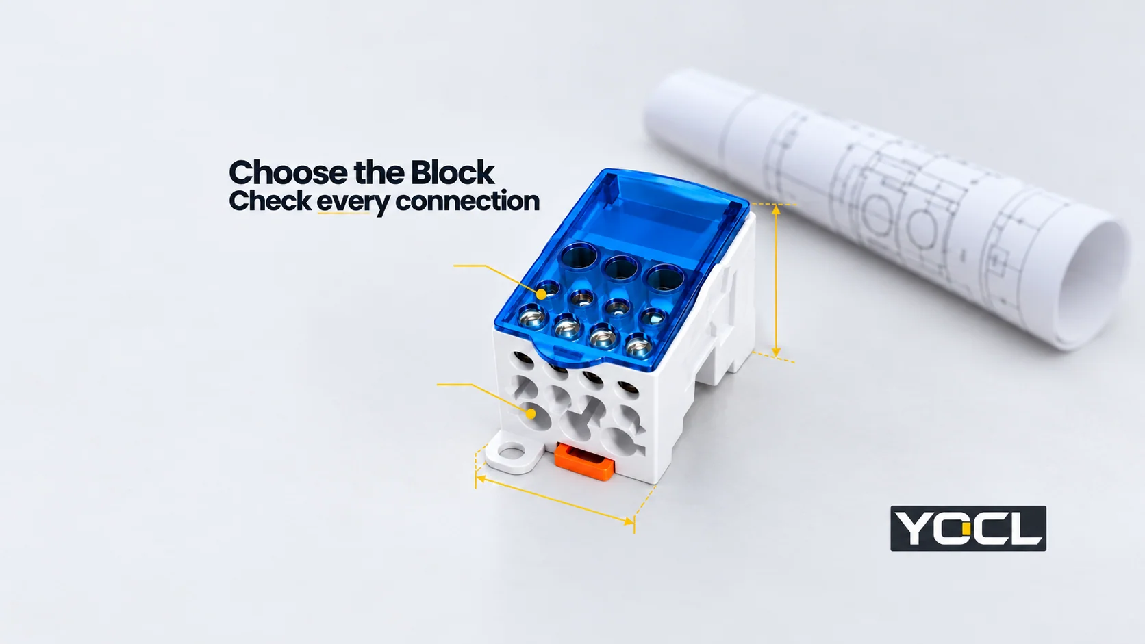
Seleccione un bloque de distribución de energía del esquema de circuitos y conductores, luego verifique la carga eléctrica del modelo exacto, cada posición de conexión, las condiciones de fallo/protección y el espacio de instalación. Una clasificación de amperaje coincidente es solo un filtro. Un bloque sigue siendo un candidato hasta que su documentación respalde la disposición del panel propuesta.
Utilice este orden:
| Fase de selección | Entrada de diseño | Requisito para incluir en la especificación |
|---|---|---|
| 1. Disposición del circuito | Nodos eléctricos comunes y recuento de derivaciones | Polos separados; posiciones de entrada/salida por polo |
| 2. Lista de conductores | Material, tamaño, construcción y extremo preparado de cada cable | Combinación de conductores aprobada en cada posición |
| 3. Servicio normal | Corriente de diseño, tensión, uso AC/DC y entorno del panel | Valores nominales del modelo exacto en las condiciones aplicables |
| 4. Revisión de fallos/protección | Corriente de fallo disponible y protección de aguas arriba/derivación | Evidencia de cortocircuito aplicable y condiciones de protección |
| 5. Integración física | Carril/fijación, dimensiones, guiado de cables y acceso | Montaje documentado y envolvente de servicio completa |
Para terminología y comportamiento de nodo común, véase ¿Qué es un bloque de distribución de energía? Entradas, salidas y clasificaciones. Esta guía convierte esos campos en una lista corta y una especificación.
1. Defina los polos y las salidas antes de comparar modelos
Empiece con el plano del cuadro. Identifique cada nodo eléctrico que deba permanecer separado y, a continuación, cuente las conexiones de salida necesarias en dicho nodo. Diez posiciones de salida en un polo común no son diez suministros aislados. No combine diferentes fases o potenciales dentro de un mismo polo.
Registre las ramas de trabajo y las reservas previstas por separado. Una conexión de reserva necesita la capacidad de conductor adecuada para su uso futuro previsto; una posición para cable pequeño sin utilizar no puede servir automáticamente para una rama futura de cable grande.
La Gama YOCL incluye diferentes disposiciones. Los modelos UKK enumeran una entrada con seis u once salidas. UTJ5 incluye tanto modelos directos de una entrada/una salida como variantes con tres o cinco salidas. Los conjuntos K tienen sus propias disposiciones multipolares. Compare el esquema del circuito y la disposición documentada, en lugar de tratar todos los productos montados en carril como intercambiables.
2. Check every conductor position, including the incoming wire
Create a row for each input and output: circuit identifier, conductor material, nominal mm² or AWG, construction/class, prepared end and permitted conductor count. Map each row to a documented connection position.
A size inside a published range is a useful screening result. Also confirm copper/aluminium acceptance, solid or stranded construction, and whether bare ends, ferrules or another preparation are permitted. The block’s conductive-body material does not establish its approved conductor materials. Nor does a twin ferrule authorize two wires in a position intended for one.
For a U.S. workplace example, OSHA 1910.303(c)(1)–(2) addresses identification for conductor materials and terminals for multiple conductors or aluminium. This is a scoped regulatory principle, not approval of a YOCL combination.
Read the available data literally:
| Información del producto YOCL | Useful screening data | Confirmation still needed |
|---|---|---|
| UKK | Model-specific input entries and grouped output-size ranges | Minimum input size where absent, conductor construction/preparation and numbered position drawing |
| UTJ5 | Individual conductor-section entries and connection configurations | Permitted range and input/output capacity at each position |
| K | Connection-hole diameters and assembly dimensions | Conductor cross-section ratings and exact circuit arrangement |
Fuentes: UKK, UTJ5 y K Series product tables. A hole diameter in millimetres is not a conductor-area rating in mm².
3. Verify current and voltage under the proposed duty
Use the design current for each common path, including the simultaneous loads and any justified future allowance. Do not multiply a block’s current rating by its output count. Do not invent a fixed safety-factor percentage or infer conductor ampacity from conductor area alone.
Check the exact voltage rating and its applicable AC/DC use. Ask for rating conditions, permissible conductor/terminal temperatures and any documented ambient-temperature derating relevant to the enclosure. Material temperature limits or a housing flammability classification are not the assembled block’s operating rating or product certification.
For example, YOCL lists UKK-160A at 160 A and UKK-250A at 250 A, both 690 V. That does not mean either model is suitable for every circuit below those headline values. The conductor schedule, rating conditions and protection review still apply.
4. Complete the fault and protection review separately
Normal-current rating and short-circuit current rating (SCCR) answer different questions. A distribution-only block does not interrupt a fault or provide individual branch protection. Obtain the relevant component fault rating or withstand evidence, voltage, and any specified protective-device conditions.
In the U.S. industrial-control-panel context, UL Solutions identifies UL 508A Supplement SB as an accepted method for determining panel SCCR. This establishes the assessment route; its motor-controller tables do not establish a distribution block’s rating. OSHA’s 1910.303(b)(4)–(5) separately addresses interrupting duty and coordination of protective devices with component short-circuit ratings.
The reviewed YOCL UKK public table supplies no SCCR value. Do not assign one from another brand’s UKK model, the upstream breaker’s interrupting rating or a generic default. Obtain the documents needed for the applicable equipment assessment. A higher-rated breaker alone does not prove the panel’s SCCR.
Verify the required evaluation category too. The public scope of UL 1953, §1.4, excludes terminal blocks covered by UL 1059. A catalogue name or transparent cover cannot establish a listing, recognition, touch-protection rating or acceptance in the intended panel.
5. Reserve space for conductors, covers and tools
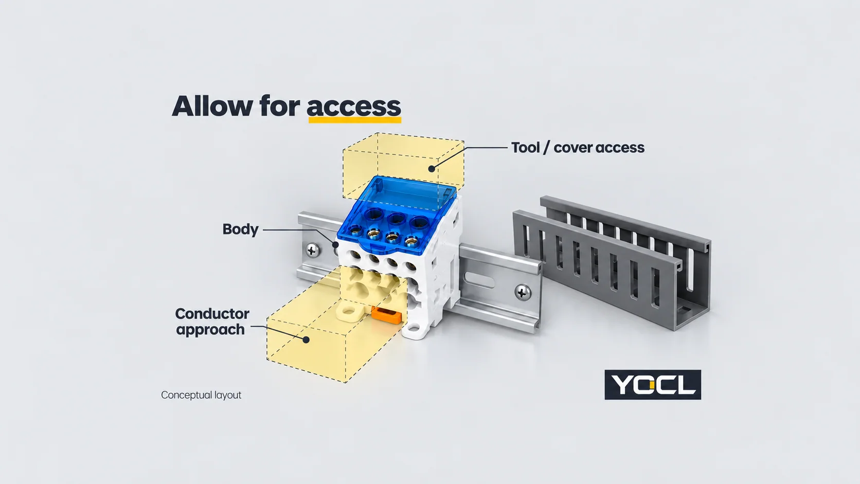
Compare the exact mounting interface and dimensional drawing with the panel layout. Allow for conductor approach and bending, wire duct, cover movement, tool access and adjacent components—not just the plastic body’s footprint. Confirm any fixing, spacing or cooling requirements from the product and equipment documentation.
YOCL lists UKK mounting on Carril 35 mm DIN and dimensions in L × A × H order. UKK-250A is 47 × 96 × 50 mm. Preserve those axis labels when placing it in the layout; do not automatically treat the first dimension as occupied rail length. A product photograph does not resolve the mounting orientation or complete installation envelope.
Worked shortlist: ten outgoing conductors on one pole
Assume an existing design specifies 200 A at 400 V AC on one common pole, una 120 mm² incoming conductor, and ten outgoing conductors: two 35 mm², three 25 mm² and five 16 mm². These are illustrative design inputs, not a cable-sizing calculation.
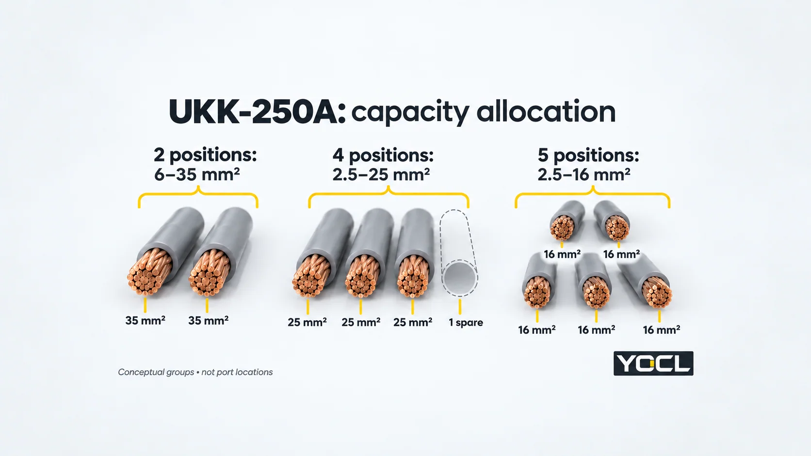
UKK-250A is a candidate for document review. Its published input entry is 120 mm² × 1; this is not a minimum-to-maximum range. Its eleven outputs can screen the schedule as follows:
| Published output group | Positions provided | Example allocation | Positions left |
|---|---|---|---|
| 6–35 mm² | 2 | Two 35 mm² wires | 0 |
| 2.5–25 mm² | 4 | Three 25 mm² wires | 1 |
| 2.5–16 mm² | 5 | Five 16 mm² wires | 0 |
The schedule uses 10 of 11 positions, leaving one in the 2.5–25 mm² group. A third 35 mm² branch would not fit this allocation; total spare count alone is insufficient.
UKK-160A is excluded by the stated 200 A requirement and by its six-output arrangement. UKK-250A passes these initial catalogue screens, but release still requires confirmation of every conductor combination, applicable 400 V AC/current conditions, fault/protection evidence and physical layout. Published dimensions and an ampere comparison do not complete those checks.
Turn the shortlist into an acceptance specification
Send one schedule containing the poles, branch count, current/voltage duty, conductor details at every position, planned spares, panel layout and target-market requirements. Request the exact-model numbered drawing, connection instructions, applicable rating conditions and short-circuit/protection documentation alongside the quotation.
Record the decision as accepted, rejected or pending evidence against each of the five selection stages. An unresolved conductor or fault-duty field stays pending; it is not passed because the block fits the rail. For model evaluation, submit that schedule with the required quantities through the YOCL power distribution block product page.
Lecturas relacionadas: comparing pin and fork comb busbars.
Referencias
- U.S. OSHA — 29 CFR 1910.303, §§(b)(4)–(5), (c)(1)–(2): scoped connection and fault-coordination requirements.
- Información del producto YOCL — Bloques de distribución de energía para carril UKK DIN, UTJ5 distribution terminal blocks y K Series: first-party model tables, checked 13 October 2026.
- UL Soluciones — Short Circuit Current Ratings for Combination Motor Controller Components, General section: panel SCCR assessment route; no motor-controller combination is transferred to YOCL blocks.
- Standards & Engagement — UL UL 1953: Esquema de investigación para bloques de distribución de energía, Edition 8, 21 November 2024: public scope §1.4 only; full paid requirements not consulted.