
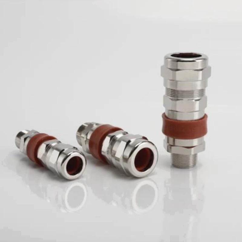
BDM-3 Explosion-Proof Single Compression Barrier Armored Cable Gland
BDM-3 single compression barrier armored cable gland for hazardous-area cable entry, used with the specified A/B two-part sealing compound.
- Brass, nickel-plated brass, SS304 or SS316 body options.
- Metric, NPT and BSP (G) entry thread options.
- Specified IP66 and IP68 protection (1 m, 1 h).
- 17 sizes for outer cable diameters from 5.5 to 88 mm across the series.
- Standard nylon washer and locknut, except for NPT versions.
Overview
The YOCL ELECTRIC BDM-3 Explosion-Proof Single Compression Barrier Armored Cable Gland provides cable entry and armor retention using a single compression construction and an A/B two-part compound barrier. The barrier configuration requires the specified compatible compound.
The product specification lists hazardous-area applications in Zones 1, 2, 21 and 22, with Ex db, Ex eb and Ex tb marking. Available body materials are brass, nickel-plated brass, SS304 and SS316.
Features
- Compound barrier: Used with the specified A/B two-part sealing compound.
- Armored cable construction: Listed for single wire armor (W), wire braid (X) and tape armor (Z) cables, including elastomer- and plastic-insulated constructions and cables with a lead inner sheath.
- Outer deluge seal: Helps limit water ingress at the gland entry.
- Thread options: Metric (M), NPT and BSP (G).
- Size options: 17 sizes with the cable and armor dimensions shown below.
Technical Specifications
| Parameter | Specification |
|---|---|
| Model | BDM-3 |
| Type | Single compression barrier armored cable gland |
| Body material options | Brass; nickel-plated brass; SS304; SS316 |
| Barrier sealing | Specified compatible A/B two-part compound |
| Operating temperature options | −20 °C to +60 °C / −60 °C to +80 °C, depending on configuration |
| Supplied Ex marking | Ex db IIC Gb; Ex eb IIC Gb; Ex tb IIIC Db |
| Ingress protection | IP66; IP68 (1 m, 1 h) |
| Listed hazardous area applications | Zone 1; Zone 2; Zone 21; Zone 22 |
| Thread options | Metric (M); NPT; BSP (G) |
| Approvals stated in supplied specification | IECEx; ATEX; EAC (CUTR); CNEx; CCC |
| Standards listed in supplied specification | IEC/EN 60079-0; IEC/EN 60079-1; IEC/EN 60079-31; IEC/EN 60079-7; IEC/EN 60529; GB 3836 |
| Standard accessories | Nylon washer and locknut, except for NPT versions |
| Optional accessories | Earth tag; PVC shroud; serrated washer; red fibre washer; A/B putty compound |
The temperature options are configuration-dependent. The supplied information does not map each temperature option to a specific seal or compound configuration and does not include certificate numbers.
Dimension
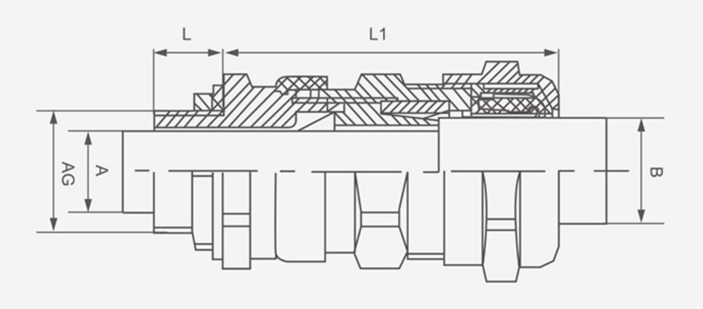
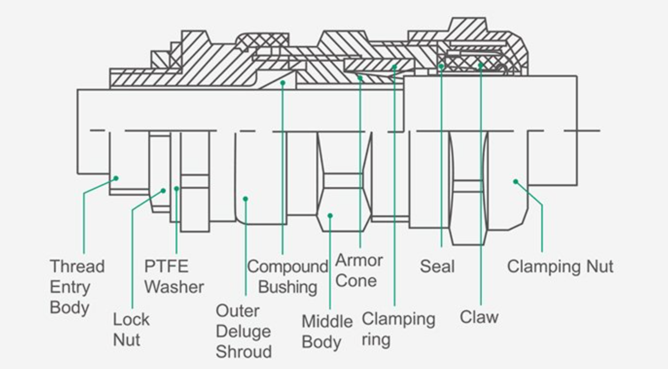
Cable and Armor Data
Dimensions are in millimetres, except the NPT/G nominal thread sizes in inches. The source lists two armor orientations separately; the values are retained as orientation 1 and orientation 2.
| Size | Metric entry thread AG | NPT/G nominal size (inch) | A (mm) | Armor orientation 1 (mm) | Armor orientation 2 (mm) | Outer sheath B (mm) |
|---|---|---|---|---|---|---|
| 16 | M16×1.5 | 3/8 | 7 | 0.3 | 1 | 5.5–12 |
| 20B | M20×1.5 | 1/2 | 11 | 0.3 | 1 | 9.5–16 |
| 20C | M20×1.5 | 1/2 | 15 | 0.3 | 1 | 12.5–20.5 |
| 25B | M25×1.5 | 3/4 | 15 | 0.3 | 1 | 12.5–20.5 |
| 25C | M25×1.5 | 3/4 | 20 | 0.4 | 1.2 | 17–26 |
| 32B | M32×1.5 | 1 | 20 | 0.4 | 1.2 | 17–26 |
| 32C | M32×1.5 | 1 | 27 | 0.4 | 1.4 | 22–33 |
| 40B | M40×1.5 | 1-1/4 | 27 | 0.6 | 1.9 | 22–33 |
| 40C | M40×1.5 | 1-1/4 | 34 | 0.6 | 2.2 | 28–41 |
| 50B | M50×1.5 | 1-1/2 | 34 | 0.8 | 2.3 | 28–41 |
| 50C | M50×1.5 | 1-1/2 | 43 | 0.9 | 2.4 | 36–52.6 |
| 63B | M63×1.5 | 2 | 43 | 0.9 | 2.4 | 36–52.6 |
| 63C | M63×1.5 | 2 | 55 | 0.9 | 2.4 | 46–65 |
| 75B | M75×1.5 | 2-1/2 | 55 | 0.9 | 2.4 | 46–65 |
| 75C | M75×1.5 | 2-1/2 | 65 | 0.9 | 2.8 | 57–78 |
| 90B | M90×1.5 | 3 | 65 | 0.9 | 2.8 | 57–78 |
| 90C | M90×1.5 | — | 75 | 0.9 | 2.8 | 68–88 |
A identifies the entry-side internal diameter shown in the source drawing. B is the cable outer sheath diameter range. A dash means no NPT/G size was supplied for that row; specify the actual thread standard when ordering.
External Dimensions
| Size | Maximum size D (mm) | Body length L1 (mm) | Entry thread length L (mm) |
|---|---|---|---|
| 16 | 29 | 70 | 16 |
| 20B | 29 | 70 | 16 |
| 20C | 37 | 73 | 16 |
| 25B | 37 | 73 | 16 |
| 25C | 44 | 79 | 16 |
| 32B | 44 | 79 | 18 |
| 32C | 55 | 84 | 18 |
| 40B | 55 | 86 | 18 |
| 40C | 67 | 95 | 18 |
| 50B | 67 | 110 | 20 |
| 50C | 73 | 110 | 20 |
| 63B | 73 | 110 | 21 |
| 63C | 89 | 117 | 21 |
| 75B | 89 | 117 | 22 |
| 75C | 116 | 125 | 22 |
| 90B | 116 | 125 | 23 |
| 90C | 130 | 130 | 23 |
L1 and L follow the source drawing: L1 is the body length beyond the entry thread; L is the entry thread length.
Accessories and Ordering
Specify the gland size, actual entry thread standard and size, cable outer diameter, armor construction and dimensions, body material, required temperature configuration and Ex specification.
A compatible A/B compound is required for the barrier construction. Although the source lists the compound as an optional accessory, it is a required functional component for this configuration; include it in the order if it is not already supplied separately.
Nylon washers and locknuts are listed as standard accessories except for NPT versions. Optional earth tags, PVC shrouds, serrated washers and red fibre washers can be specified to suit the selected installation.