
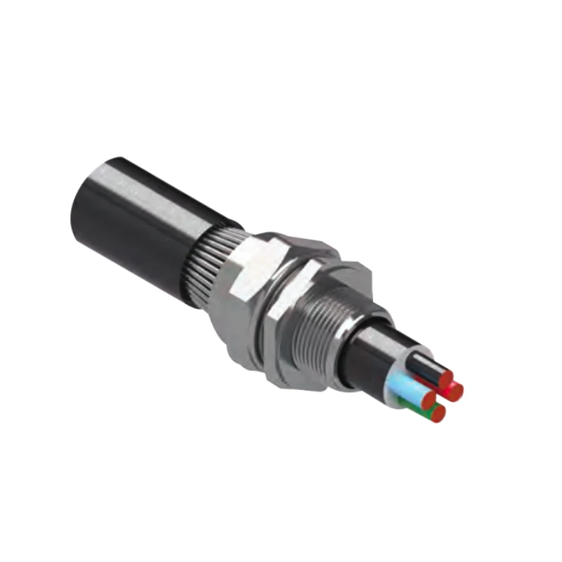
BWC Cable Gland
YOCL ELECTRIC BWC Cable Glands provide mechanical retention for armoured cable in dry indoor installations. The catalogue lists 13 models from VO-BWC001 to VO-BWC013, with metric and NPT entry thread references.
- Brass construction, with a nickel-plated option.
- IP2X ingress protection stated without a shroud.
- Model-specific cable, armour, hexagon and installation torque values are listed below.
Overview
YOCL ELECTRIC BWC Cable Glands are armoured cable glands for steel wire armoured (SWA) cable in dry indoor installations. The catalogue describes a brass body, with or without nickel plating, and mechanical retention of the cable armour. Thirteen models are listed with metric and NPT thread references.
Features
- Armour retention: the assembly is designed to grip armoured cable at the equipment entry.
- Brass body options: plain brass or nickel-plated brass as described in the catalogue.
- IP2X without a shroud: the protection grade stated for the BWC gland without the optional shroud.
- Model-specific installation torque: torque values are supplied for the listed models.
Technical Specifications
| Parameter | Specification |
|---|---|
| Series de productos | BWC |
| Cable type | Steel wire armoured (SWA) |
| Body material | Brass; nickel-plated brass option |
| Ingress protection | IP2X without a shroud |
| Intended environment | Dry indoor |
| Thread reference columns | Metric and NPT |
| Referenced standard | BS 6121, as stated in the catalogue |
| Listed models | 13 |
Dimension
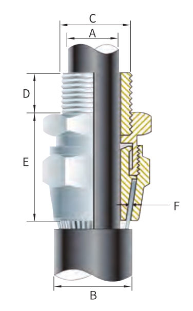
The table reproduces the source dimensions and installation torque by model. A and B are separate catalogue cable measurements; confirm their measurement points on the cable before selecting a gland. The NPT column lists alternatives where supplied. A dash means the source does not provide a value. All dimensional values are millimeters; torque is N·m.
| Model | Size | Metric thread C | Metric min D | NPT C | NPT min D | Cable max A | Cable min B | Cable max B | Max length E | Armour min F | Armour max F | Max hex flats | Max hex corners | Torque (N·m) |
|---|---|---|---|---|---|---|---|---|---|---|---|---|---|---|
| VO-BWC001 | 0-20S | M20×1.5 | 10 | 1/2 or 3/4 | 15 | 12.0 | 11.5 | 16.0 | 23.0 | 0.90 | 1.25 | 22 | 25 | 35.0 |
| VO-BWC002 | 1-20 | M20×1.5 | 10 | 1/2 or 3/4 | 15 | 15.0 | 14.5 | 20.5 | 26.0 | 0.90 | 1.25 | 25/27 | 28/30 | 35.0 |
| VO-BWC003 | 2-25 | M25×1.5 | 10 | 1/2 or 1 | 15/19 | 20.0 | 20.5 | 26.5 | 29.0 | 1.25 | 1.60 | 35 | 39 | 50.0 |
| VO-BWC004 | 3-32 | M32×1.5 | 10 | 1 or 1¼ | 19 | 26.5 | 26.5 | 33.5 | 32.0 | 1.60 | 2.00 | 42 | 47 | 70.0 |
| VO-BWC005 | 4-40 | M40×1.5 | 15 | 1¼ or 1½ | 19/21 | 34.0 | 33.0 | 42.5 | 36.0 | 1.60 | 5.00 | 52 | 59 | 90.0 |
| VO-BWC006 | 5-50 | M50×1.5 | 15 | 1½ or 2 | 21 | 44.5 | 42.5 | 52.5 | 45.0 | 2.00 | 2.50 | 65 | 73 | 100.0 |
| VO-BWC007 | 6-63 | M63×1.5 | 15 | 2 or 2½ | 21/30 | 56.5 | 52.5 | 65.5 | 50.0 | 2.00 | 2.50 | 80 | 90 | 120.0 |
| VO-BWC008 | 7-75 | M75×1.5 | 15 | 2½ or 3 | 30/32 | 67.5 | 65.5 | 78.0 | 60.0 | 2.50 | 3.15 | 96 | 108 | 120.0 |
| VO-BWC009 | 8-80 | M80×2.0 | 20 | 3 | 32 | 74.0 | 78.0 | 82.0 | 65.0 | 2.50 | 3.15 | 96 | 108 | 120.0 |
| VO-BWC010 | 9-90 | M90×2.0 | 20 | 3 or 3½ | 32/33 | 81.5 | 82.0 | 91.0 | 69.0 | 3.00 | 3.50 | 111 | 125 | 120.0 |
| VO-BWC011 | 10-100 | M100×2.0 | 20 | 3½ or 4 | 33/34 | 91.0 | 90.0 | 100.0 | 88.0 | 3.00 | 3.50 | — | — | 120.0 |
| VO-BWC012 | 11-110 | M110×2.0 | 20 | 4 | 34 | 98.0 | 100.0 | 114.0 | 88.0 | 3.00 | 4.00 | — | — | 120.0 |
| VO-BWC013 | 12-120 | M120×2.0 | 20 | — | — | 103.0 | 103.0 | 118.0 | 100.0 | 3.00 | 4.00 | — | — | 120.0 |
Selection Guide
Match the entry thread to the equipment, then check the cable’s inner and outer sheath dimensions and armour thickness against the A, B and F values. Confirm available thread engagement, maximum installed length and tool clearance before specifying the model.
Installation Notes
The supplied assembly sequence is summarized below. Use the model-specific torque in the table for the outer-to-inner gland connection.
- Measure the cable’s inner and outer sheaths with a dimension tape.
- Cut back the outer sheath to expose the armour, keeping the exposed length no longer than the outer component.
- Remove the locknut, then slide the shroud and outer component over the cable.
- Pass the cable end through the inner component and splay the armour wires over the cone.
- Tighten the outer component onto the inner component to the listed installation torque using a spanner.
- Insert the gland bush into the equipment cable entry, tighten the locknut, then slide the shroud over the gland.
Ordering Information
Provide the full BWC model code, cable and armour dimensions, thread form, required finish and quantity when requesting a quotation.