
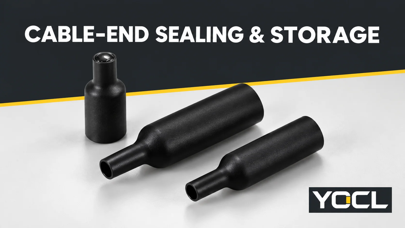
A термоусаживаемый концевой колпачок представляет собой закрытый колпачок, используемый для защиты оголенного конца кабеля. Его входное отверстие усаживается вокруг кабеля, а конструкция с клеевым слоем образует соединение с соответствующей поверхностью кабеля при соблюдении указанного процесса монтажа. Предназначен для защиты конца кабеля во время хранения, транспортировки или при выполнении регламентированных работ по герметизации концов.
Концевой колпачок не соединяет проводники, не делает кабель безопасным для обращения и автоматически не является концевой заделкой для цепи под напряжением. Он закрывает границу, отличную от сквозных трубок, описанных в обзоре термоусаживаемых трубок.
Что закрывает концевой колпачок?
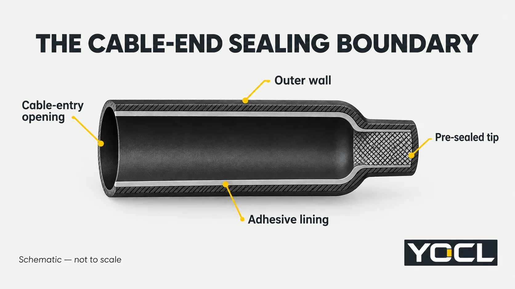
Сквозная трубка имеет проход через оба конца. Концевой колпачок для кабеля имеет монтажное отверстие и предварительно запаянный торец. Его корпус закрывает конец кабеля; входная сторона обеспечивает соединение с оболочкой кабеля или другой поверхностью, указанной в инструкции по применению.
YOCL’s current HSC-F и HSC-B drawings identify two material functions:
- Outer wall: the recoverable covering that encloses and protects the cable-end region.
- Внутренний слой с термоплавким клеем: the interface material intended to form a bond with the specified cable surface during application and cooling.
The closed tip and the cable-entry interface must be considered together. A cap with an intact tip can still have an unsuitable entry interface. A close-looking fit around the jacket does not, on its own, verify the complete seal.
The surface receiving the adhesive matters. A smooth outer jacket, an irregular group of individual wires and a layered power-cable construction are different sealing problems. A product photograph showing a harness application cannot establish that every wire bundle or cable construction will form a suitable seal.
Why Cable-End Sealing Matters During Storage
An exposed cut end creates a different moisture-entry path from damage along the cable jacket. Protecting the cable’s outside surface does not address an end left open during storage or handling.
A useful industry example is Horizon Power’s LV Power Cables specification, revision 4, dated 13 July 2026. Section 3.8 requires cables supplied under that specification to be free of water or corrosion and to have their ends sealed, with the sealing method documented. It also addresses separation of cable layers against water transfer.
That is an Australian utility’s procurement requirement. It shows why the cable construction and sealing method belong in a storage specification; it does not approve a particular YOCL cap or prove that an external cap alone meets every layered-cable requirement.
Covering a cable end and accepting its condition are separate decisions. If an end is already wet, contaminated or damaged, applying a cap does not establish that the cable underneath is acceptable. Its disposition belongs to the cable supplier’s or project’s assessment process.
Two YOCL Product Paths: HSC-F and HSC-B
The current YOCL range lists these end caps separately from open-ended tubing. Both use adhesive-lined, closed-end construction, but they have their own model tables and declared properties.
| Product path | Declared construction | Listed colours | Declared operating range | Next document to review |
|---|---|---|---|---|
| HSC-F | Radiation-modified polyolefin outer layer with hot-melt lining; listed 4:1 recovery | Black or Transparent | −45°C to +125°C | HSC-F model dimensions, length options and application requirements |
| HSC-B | Semi-rigid radiation cross-linked polyolefin outer wall with hot-melt lining; nominal 4:1 recovery | Черный | −45°C до +110°C | HSC-B model dimensions, A/B length notation and application requirements |
Это YOCL catalogue declarations, not a comparative field test or an approval of a particular cable-end seal. HSC-F lists three models and HSC-B five. A shared recovery ratio does not make their dimensions, lengths, wall properties or application requirements interchangeable.
Используйте HSC-F product information when reviewing that family, and the HSC-B product information for the semi-rigid family. The operating ranges describe service conditions. They are not heating-tool settings, an unopened-product shelf life or a guarantee of a storage duration.
Colour and rigidity are specification choices, not substitutes for sealing evidence. A transparent option may help visibility, but visual access does not prove a complete adhesive interface. A semi-rigid outer wall also does not establish a pulling-load or impact rating.
Where Storage and Handling Change the Decision
Cable-end protection needs to remain identifiable as the cable moves from supply to use. The important events are changes to the end, its exposure or its acceptance status.
| Event or condition | End-cap question | Information to retain or request |
|---|---|---|
| Receipt into storage | Are the relevant cable ends protected, and is their condition acceptable? | Cable identity, supplier sealing arrangement and any observed damage or moisture concern |
| Transport or handling | Has the end protection been punctured, displaced or otherwise disturbed? | Affected location and disposition under the cable or project procedure |
| Cable cut to a new length | What protection is required for each newly exposed end? | The new cable-end condition, applicable sealing method and suitable cap reference |
| Seal removed for inspection or preparation | What is required before the end returns to storage? | Approved replacement or resealing instructions; do not assume the removed cap is reusable |
| Handover for installation | Has storage protection been distinguished from the final electrical work? | Cable condition and release record, followed by the required termination or splice documents |
This is a handover map, not a fixed inspection interval. Storage duration, outdoor exposure, handling damage and the cable manufacturer’s requirements determine what the project needs to control.
Retain the cable identification when an end is covered. If an end is opened or recut, the old seal record no longer establishes the condition of the new end. The replacement protection and acceptance record should refer to the cable length actually being handed over.
Match the Next Question to the Right Resource
End-cap selection and sleeve installation are related, but their dimensions and application boundaries differ. Use the resource that owns the next task.
| Your next task | Start here | Keep this boundary |
|---|---|---|
| Identify a cap candidate for a particular cable end | The HSC-F or HSC-B model documents linked above | Use the cap’s own diameter limits, usable coverage and length definitions. A tubing size chart is not a cap-selection approval. |
| Understand the wider sleeve landscape | Heat shrink tubing overview | Open sleeves, ratios and wall construction are covered there; a closed end introduces another boundary. |
| Cover an accepted electrical splice with open tubing | How to select and apply heat shrink tubing to a cable splice | That procedure concerns a splice and sleeve. It is not an end-cap installation instruction. |
| Investigate split material or unresolved sealing evidence | Why heat shrink tubing splits or fails to seal | The article explains the separate sleeve-diagnosis task. Cap-specific rework still needs the cap’s instructions. |
For cap fit, the key document fields are the supplied internal diameter, recovered diameter limit, required cable coverage, length definitions and material/interface suitability. They belong to one selected model and application. Do not combine a diameter from one cap with a length or wall value from another.
Recovery is only one part of the application. Obtain the preparation, heating, cooling and acceptance instructions for the selected cap rather than treating the shared “4:1” label as an installation recipe. Detailed sizing and application work should follow those documents.
What the Cap Does Not Establish
A cable-end seal addresses a defined end and exposure. It does not repair a damaged jacket farther along the cable, dry a wet construction or provide conductor continuity. A material’s insulation property also does not assign a working voltage to the complete capped cable end.
Specify environmental exposure explicitly. General moisture protection, prolonged outdoor storage, immersion, chemical exposure and pressure are different requirements. Ask for evidence covering the completed arrangement and the required conditions. The words “waterproof” or “adhesive-lined” alone do not assign an unspecified ingress-protection class or immersion duration.
Storage protection also needs to remain separate from electrical isolation. Before handling or applying heat to electrical cable ends, follow the authorized safe-work and isolation arrangements. The UK HSE’s Electricity at work: Safe working practices, third edition, paragraphs 47–55, describes identification, isolation and proving dead. An end cap is not a replacement for those controls or an automatic authorization to energize an unused conductor.
Prepare a Reviewable End-Cap Enquiry
Provide the cable construction and jacket material, the end or feature dimensions, required coverage, intended storage or service exposure, and the proposed HSC-F or HSC-B model if one has been identified. Include colour, quantity and any project-specific sealing or documentation requirements.
Используйте YOCL heat-shrink product range to request the applicable cap dimensions, application instructions and evidence for the intended duty. This turns a general request for an end cap into a review of the actual cable-end interface and protection requirement.
Ссылки
- , YOCL ELECTRIC — HSC-F 4:1 Dual-Wall Heat Shrink End Cap, first-party product construction, model fields and original section; accessed 27 October 2026.
- , YOCL ELECTRIC — HSC-B Semi-Rigid Dual-Wall Heat Shrink End Cap, first-party product construction, model fields and original section; accessed 27 October 2026.
- Horizon Power — Specification — LV Power Cables, HPC-8DJ-03-0003-2012, revision 4, 13 July 2026, section 3.8, cable-end sealing for its LV cable procurement scope.
- UK Health and Safety Executive — Electricity at work: Safe working practices, HSG85, third edition, 2013, paragraphs 47–55; safe-work principles.