
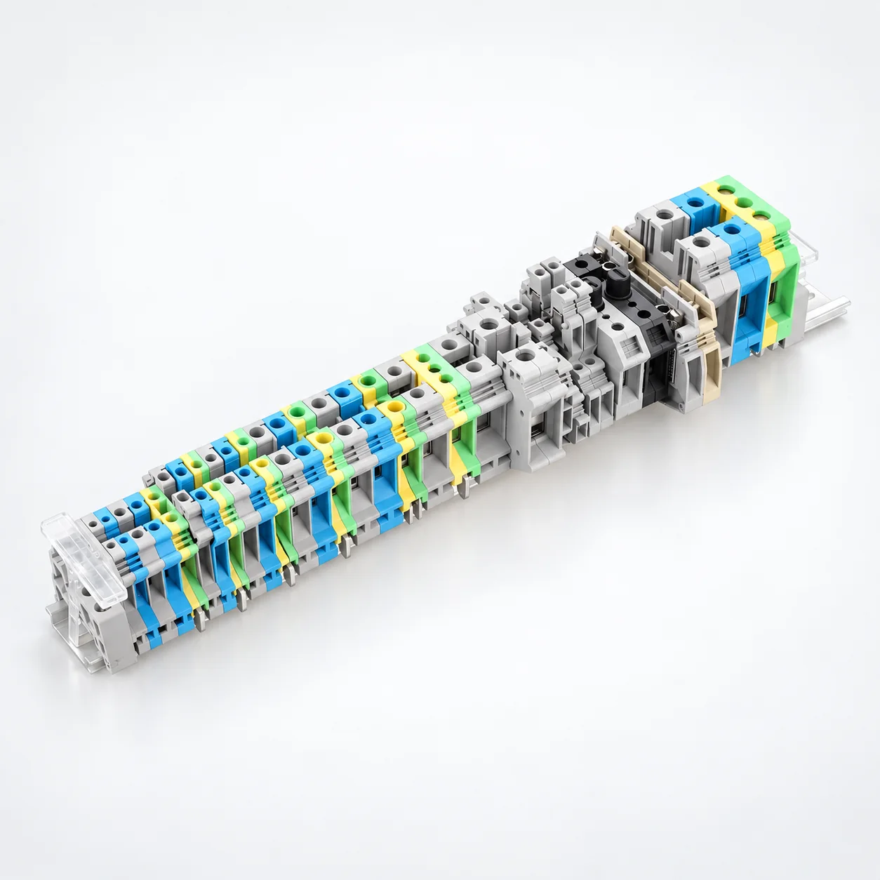
UK Серия Винтовые DIN Клеммные колодки на DIN-рейку
YOCL ELECTRIC UK Series Screw DIN Rail Terminal Blocks provide screw-clamp conductor connections for electrical panels and DIN rail assemblies.
- PA66 nylon insulating housings and brass conductive components.
- 36 listed models, including standard feed-through, compact, multi-level and protective-earth terminals.
- Yellow-green USLKG models for protective-earth connections.
- Individual current and voltage ratings, dimensions, stripping lengths and screw sizes.
- Rigid and flexible conductor ranges listed for selected models.
- Model-specific center-type jumper and end plate options.
Overview
YOCL ELECTRIC UK Series Screw DIN Rail Terminal Blocks provide conductor connections and circuit organization in electrical panels, control cabinets and DIN rail assemblies. The series uses a screw-clamp connection with a PA66 nylon insulating housing and brass conductive components.
The range includes standard feed-through, compact, multi-level, twin-connection, disconnect and special-function configurations, plus yellow-green USLKG protective-earth terminals. Current and voltage ratings, dimensions, stripping lengths and screw sizes vary by model. Rigid and flexible conductor ranges are listed for selected models below.
Features
- Screw-clamp connections: Conductors are secured by the terminal screw.
- DIN rail mounting: Individual terminals can be arranged side by side in a terminal assembly.
- PA66 nylon housing and brass components: Insulating housings and conductive components use the listed materials.
- Multiple configurations: Standard, compact, multi-level and other configurations support different circuit layouts.
- Protective-earth models: Yellow-green USLKG terminals are available for PE connections.
- Jumper and end plate options: Model-specific accessories support potential distribution and terminal assembly.
Technical Specifications
| Parameter | Specification |
|---|---|
| Brand | YOCL ELECTRIC |
| Series | UK |
| Product Type | Screw DIN Rail Terminal Block |
| Connection Method | Screw Clamp |
| Mounting | DIN rail |
| Housing Material | PA66 nylon |
| Conductive Component Material | Brass |
| Colors | Grey, black and green across the range; yellow-green for USLKG protective-earth models |
| Rated Current and Voltage | Model dependent; see model tables |
| Conductor Range | Rigid and flexible ranges listed for 12 models below |
| Stripping Length | Model dependent; see model tables |
| Screw Size | M2, M3, M4, M6, M8 or M10, depending on model |
| Jumper | Model-specific center-type jumper options |
| End Plate | Model dependent; enclosed-housing models listed below require no separate end plate |
Dimension
Dimensions are listed in L × W × H order, in millimetres. Each row provides the electrical ratings, stripping length and screw size for that model.
Standard UK Terminal Models
| Model | Rated Current | Rated Voltage | Dimensions (L × W × H) | Stripping Length | Screw |
|---|---|---|---|---|---|
| UK-1.5N | 17.5 A | 400 V | 42.5 × 42 × 4.2 mm | 7 mm | M2 |
| UK-2.5B | 32 A | 400 V | 42.5 × 42 × 6.2 mm | 8 mm | M3 |
| UK-3N | 32 A | 400 V | 42.5 × 47 × 5.2 mm | 8 mm | M3 |
| UK-5N | 41 A | 400 V | 42.5 × 47 × 6.2 mm | 8 mm | M3 |
| UK-6N | 57 A | 800 V | 42.5 × 47 × 8.2 mm | 10 mm | M4 |
| UK-10N | 76 A | 800 V | 42.5 × 47 × 10.2 mm | 12 mm | M4 |
| UK-16N | 101 A | 800 V | 42.5 × 47 × 12.2 mm | 14 mm | M4 |
| UK-25N | 110 A | 800 V | 42.5 × 47 × 14.2 mm | 14 mm | M4 |
| UK-35N | 125 A | 800 V | 51.2 × 62 × 15.2 mm | 16 mm | M6 |
| UIK-35N | 125 A | 800 V | 55 × 51 × 16 mm | 16 mm | M6 |
| UK-50N | 150 A | 800 V | 70.5 × 83.5 × 20.1 mm | 24 mm | M6 |
| UK-95N | 232 A | 1000 V | 83 × 97.5 × 25.2 mm | 33 mm | M8 |
| UK-150N | 309 A | 1000 V | 100 × 119 × 31 mm | 40 mm | M10 |
| UK-240N | 415 A | 1000 V | 101 × 125 × 36 mm | 40 mm | M10 |
Compact and Multi-Level Models
| Model | Rated Current | Rated Voltage | Dimensions (L × W × H) | Stripping Length | Screw |
|---|---|---|---|---|---|
| MBK3 | 32 A | 400 V | 28 × 31.5 × 5.2 mm | 8 mm | M3 |
| MBKKB-2.5 | 24 A | 400 V | 62 × 48 × 5.2 mm | 7 mm | M3 |
| MBKKB-2.5-LA | 24 A | 400 V | 62 × 48 × 5.2 mm | 7 mm | M3 |
| UDK4 | 32 A | 800 V | 63.5 × 47 × 6.2 mm | 8 mm | M3 |
| MTKP-P | 16 A | 800 V | 46 × 51.5 × 5.2 mm | 7 mm | M3 |
| UKK3 | 32 A | 800 V | 56 × 62 × 5.2 mm | 8 mm | M3 |
| UKK5 | 32 A | 800 V | 56 × 62 × 6.2 mm | 8 mm | M3 |
| URTK-4S | 57 A | 800 V | 42.5 × 50 × 8.2 mm | 10 mm | M4 |
| URTK-6S | 57 A | 800 V | 72.5 × 50 × 8.2 mm | 10 mm | M4 |
| UK5-HESI | 6.3 A | 800 V | 72.5 × 56.5 × 8.2 mm | 8 mm | M3 |
Models with Specified Conductor Ranges
The following three models list both rigid and flexible conductor ranges. These ranges apply to the indicated model.
| Model | Rigid Conductor | Flexible Conductor | Rated Current | Rated Voltage | Stripping Length | Dimensions (L × W × H) | Screw |
|---|---|---|---|---|---|---|---|
| UK-10RD | 0.5–16 mm² | 0.5–16 mm² | 10 A | 800 V | 11 mm | 62 × 59 × 12 mm | M4 |
| UK-5NTWIN | 0.2–10 mm² | 0.2–4 mm² | 32 A | 800 V | 8 mm | 50.5 × 47 × 6.5 mm | M3 |
| DIK-1.5 | 0.2–4 mm² | 0.2–2.5 mm² | 30 A | 800 V | 8 mm | 73 × 54 × 6.2 mm | M3 |
Protective Earth Terminal Blocks
Yellow-green USLKG terminals provide protective-earth configurations with the following model-specific data.
| Model | Rigid Conductor | Flexible Conductor | Rated Current | Rated Voltage | Dimensions (L × W × H) | Strip Length | Screw |
|---|---|---|---|---|---|---|---|
| USLKG-2.5 | 0.2–4 mm² | 0.2–2.5 mm² | 32 A | 800 V | 43.5 × 41 × 6.2 mm | 7 mm | M3 |
| USLKG-3 | 0.2–4 mm² | 0.2–2.5 mm² | 32 A | 800 V | 42.5 × 42 × 5.2 mm | 7 mm | M3 |
| USLKG-5 | 0.2–4 mm² | 0.2–4 mm² | 41 A | 800 V | 42.5 × 47 × 6.2 mm | 9 mm | M3 |
| USLKG-6 | 0.2–10 mm² | 0.2–6 mm² | 57 A | 800 V | 42.5 × 47 × 8.2 mm | 10 mm | M4 |
| USLKG-10 | 0.5–10 mm² | 0.5–6 mm² | 76 A | 800 V | 42.5 × 47 × 10.2 mm | 10 mm | M4 |
| USLKG-16 | 2.5–25 mm² | 4–16 mm² | 101 A | 800 V | 42.5 × 54 × 12.2 mm | 11 mm | M4 |
| USLKG-35 | 0.75–50 mm² | 0.75–30 mm² | 125 A | 800 V | 50 × 62 × 15.2 mm | 15 mm | M6 |
| USLKG-50 | 16–50 mm² | 25–50 mm² | 150 A | 800 V | 71 × 83.5 × 20 mm | 24 mm | M6 |
| USLKG-95 | 25–95 mm² | 35–95 mm² | 232 A | 800 V | 71 × 99 × 25 mm | 30 mm | M8 |
Selection Guide
Select the terminal configuration, then check the current rating, voltage rating, dimensions, stripping length and screw size for that exact model. For example, UK-240N is rated 415 A at 1000 V, while UK-10RD is rated 10 A at 800 V. These ratings belong to the individual models.
Use the stated rigid or flexible conductor range where provided. Conductor capacity cannot be determined from the model name alone. For USLKG-35, the listed ranges are 0.75–50 mm² for rigid conductors and 0.75–30 mm² for flexible conductors.
Standard terminal models are predominantly grey. Select color by model; yellow-green is specified for the USLKG protective-earth range.
Jumpers, End Plates and Enclosed Housings
Multiple models support center-type jumpers for potential distribution between adjacent terminals. Jumper examples include FB1, EB1 and EBL, alongside model-specific configurations. Match the jumper to the selected terminal model.
End plates are specified for applicable terminal sizes. The following models have enclosed housings and require no separate end plates:
- UK-35N
- UIK-35N
- UK-50N
- UK-95N
- UK-150N
- UK-240N
Specify any required jumper, end plate or other accessory with the terminal model it will be used with.
Применение
- Industrial control cabinets and electrical distribution panels.
- Automation equipment and machine control systems.
- Equipment internal wiring.
- DIN rail terminal assemblies.
- Control and power distribution circuits.
Ordering Information
For a quotation, provide the terminal model, quantity, circuit current and voltage requirements, conductor size and conductor type. Include the required configuration, color and any compatible jumper, end plate or other accessory.