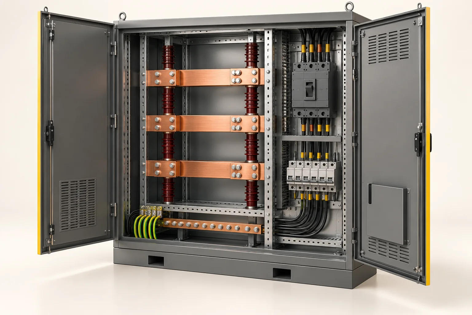
Application illustration — not a project reference or installation drawing.
Keep every connection interface in the specification.
Connect the conductors
Separate cable-end terminations from in-line joints, then specify the conductor material and connection geometry for each item.
What to check
State conductor material and cross-section, stud size, palm dimensions and the intended equipment connection. Request the model-specific installation and tooling requirements.
Select supports against the assembly designer’s electrical and mechanical requirements. Dimensions alone do not establish suitability.
What to check
Provide support height, mounting thread and busbar arrangement. The assembly designer must verify clearances, creepage, thermal conditions and short-circuit withstand.
Match splice and distribution components to the number, material and size of the incoming and outgoing conductors.
What to check
Include the intended connection arrangement and the project’s electrical requirements. Ratings and conductor compatibility must be checked for the specific model.
A clear specification helps us discuss the right models with you.
Conductor material, cross-section and cable construction
Stud, palm, splice and mounting dimensions
Busbar layout and designer-specified requirements
Model quantities, drawings and documentation needs
These guides support component sourcing, not system design or installation. Suitability, ratings and compliance must be verified for the selected models and the completed assembly.
Discuss your distribution parts list
Share your application, part references and quantities with YOCL.

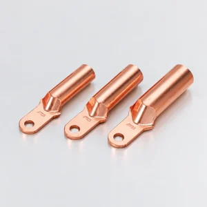 Copper Cable Lugs
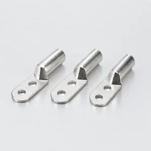 Aluminium Cable Lugs
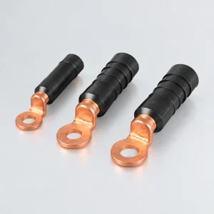 Bimetallic Cable Lugs
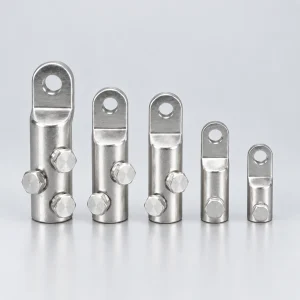 Mechanical Cable Lugs
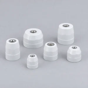 Busbar Supports & Insulators
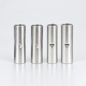 Copper Connecting Sleeves
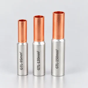 Bimetallic Connecting Sleeves
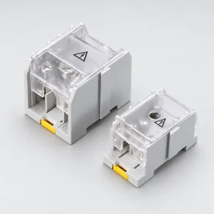 Power Distribution Blocks