
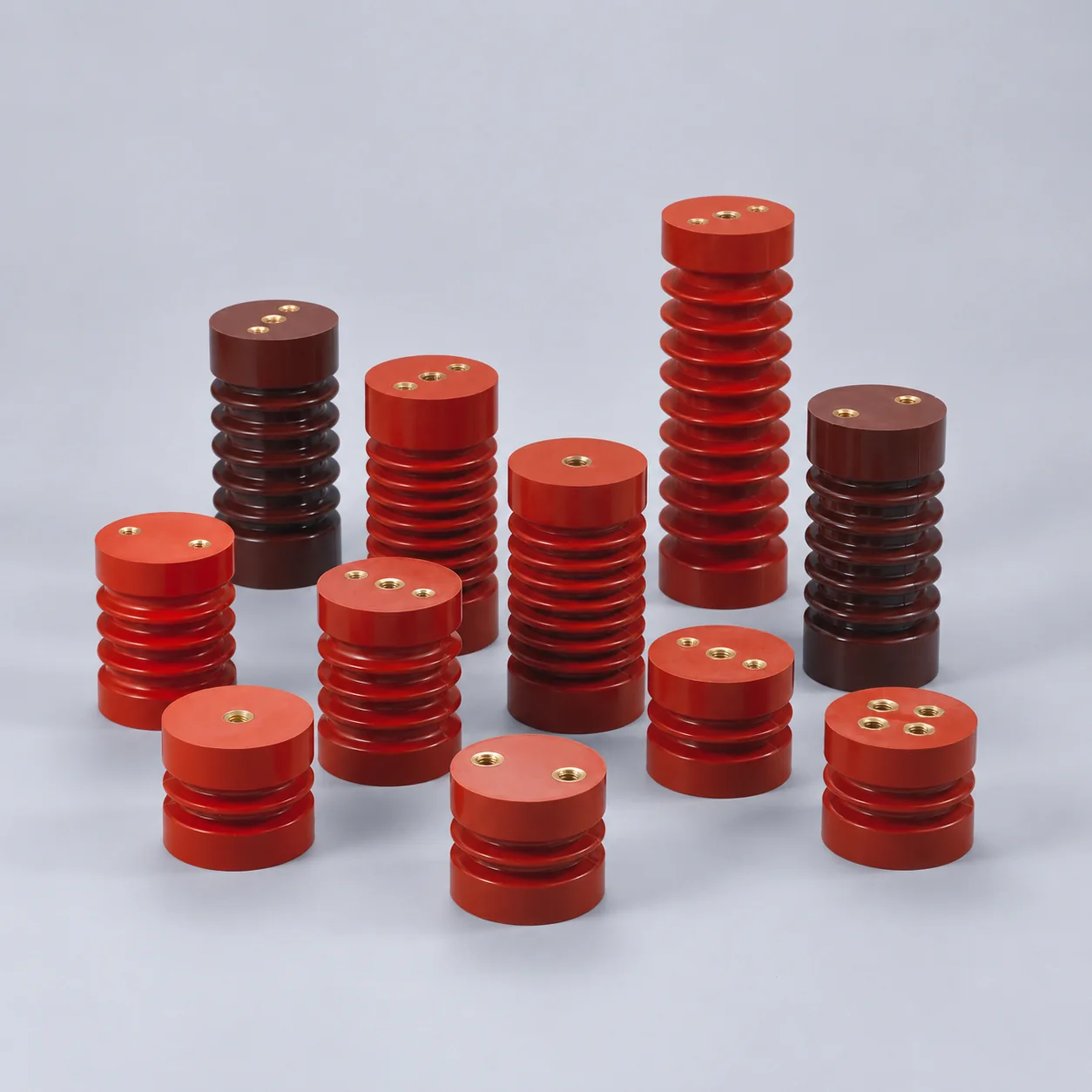
EL Series Busbar Clamps
EL series busbar clamps provide grooved mounting components for supporting and positioning busbars.
- Thirteen models with lengths from 100 to 500 mm.
- Model-specific groove widths and mounting hole labels.
- End/profile widths from 30 to 36 mm.
- EL-270 A/B groove dimensions listed as matched pairs.
- EL-270/D retained as a separate model.
Übersicht
YOCL ELECTRIC EL series busbar clamps provide grooved mounting components for supporting and positioning busbars. The range includes thirteen models with overall lengths from 100 to 500 mm.
Groove widths, end profiles and mounting hole labels vary by model. Select using the complete model drawing and the busbar arrangement to be supported.
Merkmale
- Thirteen models with lengths from 100 to 500 mm.
- Grooved bodies for positioning busbars.
- Model-specific mounting hole and groove labels.
- Separate EL-270 and EL-270/D designs.
- EL-270 groove options listed as paired A/B dimensions.
Technische Daten
| Parameter | Spezifikation |
|---|---|
| Serie | EL busbar clamps |
| Function | Support and positioning of busbars |
| Model count | 13 |
| Listed length range | 100–500 mm |
Abmessung
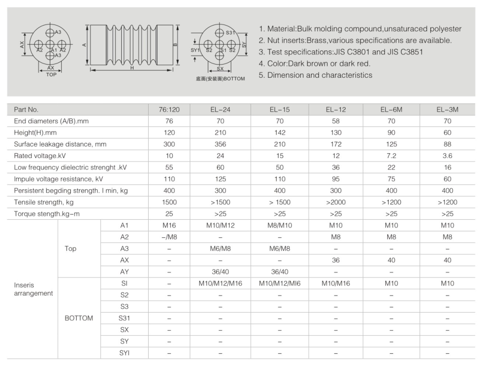
| Model | Overall length (mm) | End/profile width (mm) | Overall height (mm) |
|---|---|---|---|
| EL-100 | 100 | 36 | 40 |
| EL-125 | 125 | 36 | 40 |
| EL-130 | 130 | 35 | 35 |
| EL-180 | 180 | 34 | 28.1 |
| EL-210 | 210 | 34 | Not specified |
| EL-220 | 220 | 36 | 40 |
| EL-270 | 270 | 35 | 35 |
| EL-270/D | 270 | 30 | 40 |
| EL-271 | 271 | 36 | 40 |
| EL-295 | 295 | 35 | 35 |
| EL-370 | 370 | 36 | 40 |
| EL-409 | 409 | 35 | 35 |
| EL-500 | 500 | 36 | 40 |
Hole and Groove Labels
| Model | Hole callouts as labelled (mm) | Groove width labels (mm) |
|---|---|---|
| EL-100 | φ15×2; φ8×2 | Top: 6 / 6; bottom: 10 / 10 |
| EL-125 | φ15×2; φ8×2 | Top: 10 / 10; bottom: 12 / 12 |
| EL-130 | φ12×2; φ8×2 | Top: 9 / 11; bottom: 6.5 / 6 |
| EL-180 | φ9×2; φ7×2 | A: 7 or 11 |
| EL-210 | φ16.5×2 | W: 7 or 11 |
| EL-220 | φ15×2; φ8×2 | Top: 6; bottom: 10 |
| EL-270 | φ12×2 | A/B pairs: 12/7; 12/0; 11/6; 10/5 |
| EL-270/D | φ8×2 | Top: 6; bottom: 10 |
| EL-271 | φ15×2; φ8×2 | Top: 10; bottom: 12 |
| EL-295 | φ11×3 | Top: 11; bottom: 6 |
| EL-370 | φ15×4; φ8×4 | Top: 10; bottom: 12 |
| EL-409 | φ20×2; φ12×2 | Labels: 10 / 11 / 9 / 6.3 |
| EL-500 | 4-φ10.25 | Top: 6.5 / 6; bottom: 9 / 11 |
EL-270 Paired Groove Dimensions
| A (mm) | B (mm) |
|---|---|
| 12 | 7 |
| 12 | 0 |
| 11 | 6 |
| 10 | 5 |
A and B are paired drawing labels; select one complete pair. EL-180 uses the label A for 7 or 11 mm groove options, while EL-210 uses W for its 7 or 11 mm options. Hole callouts retain the supplied notation; dimensions from different views should be matched to the complete drawing.
Auswahlhilfe
Select the model by overall length, end profile, groove dimensions and mounting features. EL-270/D is a separate 270 mm model with a 30 mm end/profile width and 40 mm height; EL-270 lists 35 mm for both dimensions. Confirm the required mating clamp or support arrangement for the chosen busbar layout.
Bestellinformationen
For a quotation, specify the EL clamp model, required groove option, quantity, busbar dimensions and mounting layout. For EL-270, state the paired A/B values.