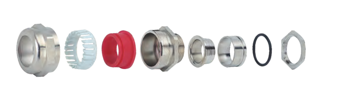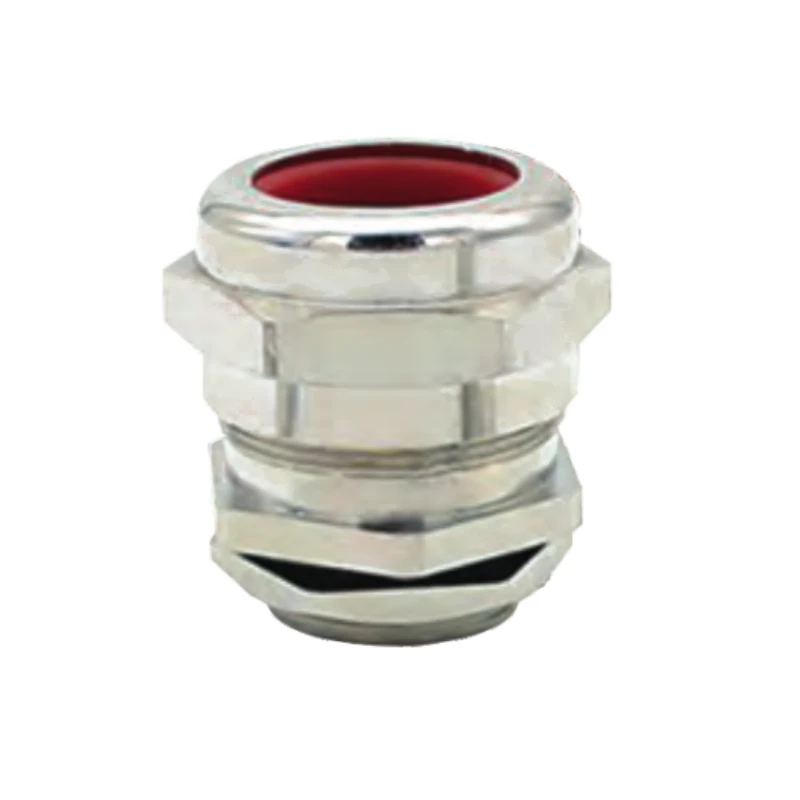
VO-1 Single Seal Explosion-Proof Cable Gland
The VO-1 single-seal explosion-proof cable gland is listed for armoured cable connections. Select a size by the specified cable dimensions and entry thread.
- Metric, NPT and G thread code options are listed in the source catalogue.
- 21 size rows span Metric M16 to M110, with model-specific cable ranges and gland dimensions.
- The catalogue describes cable fastening and sealing for armoured cable installations.
- Ask for the applicable hazardous-area certification and installation instructions when specifying an Ex installation; neither is provided in the source pages.
Overview
The VO-1 Single Seal Explosion-Proof Cable Gland is a catalogue series for armoured cable entry and sealing. The supplied size chart lists Metric, NPT and G entry-thread codes for 21 cable-size rows. The exact cable range and body dimensions depend on the selected code.
The source describes mechanical cable retention and sealing for armoured cable installations. The supplied pages do not state an Ex marking, certificate number, gas or dust group, temperature class, ingress-protection rating or installation torque. Check those requirements against the applicable product documentation before specifying the gland for a hazardous area.
Features
- Single-seal gland configuration as identified in the source catalogue.
- Thread code options for Metric, NPT and G entries.
- Size-specific cable ranges and hexagonal dimensions support model selection.
- Intended for armoured cable connection according to the supplied overview.
Technical Specifications
| Parameter | Catalogue information |
|---|---|
| Series | VO-1 |
| Seal configuration | Single seal |
| Intended cable | Armoured cable |
| Entry thread families | Metric, NPT and G |
| Metric entry threads | M16 × 1.5 through M75 × 1.5; M88 × 2 and M110 × 2 |
| Catalogue size rows | 21 |
| Cable range and dimensions | Vary by model; see table below |
Dimension
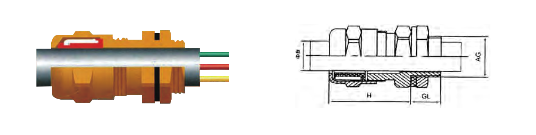
The catalogue uses B and A for two cable-range dimensions, H and L for gland dimensions, and across-flats/across-corners values for the hexagonal body. All dimensional values in the table are in millimetres. The column headings are reproduced as supplied; check the matching installation drawing before applying A and B to a specific cable construction.
| Metric code | Metric thread | NPT code | NPT thread | G code | Cable B | Cable A | H | L | Across flats | Across corners |
|---|---|---|---|---|---|---|---|---|---|---|
| VO-08-M16 | M16 × 1.5 | VO-08-NPT3/8 | 3/8″ | VO-08-G3/8 | 5–8 | 3–6 | 30 | 12 | 24 | 28 |
| VO-10-M16 | M16 × 1.5 | VO-10-NPT3/8 | 3/8″ | VO-10-G3/8 | 6–10 | 4–8 | 30 | 12 | 24 | 28 |
| VO-14-M20 | M20 × 1.5 | VO-14-NPT1/2 | 1/2″ | VO-14-G1/2 | 9–14 | 6–11 | 30 | 12 | 24 | 28 |
| VO-16-M20 | M20 × 1.5 | VO-16-NPT1/2 | 1/2″ | VO-16-G1/2 | 10–16 | 7–12 | 30 | 12 | 24 | 28 |
| VO-18-M20 | M20 × 1.5 | VO-18-NPT1/2 | 1/2″ | VO-18-G1/2 | 13–18 | 9–14 | 32 | 12 | 30 | 35 |
| VO-21-M25 | M25 × 1.5 | VO-21-NPT3/4 | 3/4″ | VO-21-G3/4 | 15–21 | 11–17 | 35 | 13 | 36 | 42 |
| VO-24-M25 | M25 × 1.5 | VO-24-NPT3/4 | 3/4″ | VO-24-G3/4 | 17–24 | 13–20 | 35 | 13 | 40 | 47 |
| VO-28-M32 | M32 × 1.5 | VO-28-NPT1 | 1″ | VO-28-G1 | 20–28 | 16–23 | 39 | 15 | 46 | 53 |
| VO-32-M32 | M32 × 1.5 | VO-32-NPT1 | 1″ | VO-32-G1 | 23–32 | 18–26 | 39 | 15 | 46 | 53 |
| VO-35-M40 | M40 × 1.5 | VO-35-NPT1-1/4 | 1-1/4″ | VO-35-G1-1/4 | 26–35 | 21–29 | 43 | 15 | 55 | 64 |
| VO-38-M40 | M40 × 1.5 | VO-38-NPT1-1/4 | 1-1/4″ | VO-38-G1-1/4 | 31–38 | 25–32 | 43 | 15 | 55 | 64 |
| VO-41-M50 | M50 × 1.5 | VO-41-NPT1-1/2 | 1-1/2″ | VO-41-G1-1/2 | 34–41 | 28–35 | 48 | 15 | 65 | 75 |
| VO-44-M50 | M50 × 1.5 | VO-44-NPT1-1/2 | 1-1/2″ | VO-44-G1-1/2 | 37–44 | 31–38 | 48 | 15 | 65 | 75 |
| VO-50-M63 | M63 × 1.5 | VO-50-NPT2 | 2″ | VO-50-G2 | 40–50 | 33–43 | 53 | 16 | 80 | 92 |
| VO-55-M63 | M63 × 1.5 | VO-55-NPT2 | 2″ | VO-55-G2 | 43–55 | 36–47 | 53 | 16 | 80 | 92 |
| VO-63-M75 | M75 × 1.5 | VO-63-NPT2-1/2 | 2-1/2″ | VO-63-G2 | 50–63 | 42–53 | 58 | 16 | 96 | 111 |
| VO-68-M75 | M75 × 1.5 | VO-68-NPT2-1/2 | 2-1/2″ | VO-68-G2-1/2 | 54–68 | 45–58 | 58 | 16 | 96 | 111 |
| VO-72-M88 | M88 × 2 | VO-72-NPT3 | 3″ | VO-72-G3 | 62–72 | 52–62 | 64 | 18 | 114 | 134 |
| VO-79-M88 | M88 × 2 | VO-79-NPT3 | 3″ | VO-79-G3 | 67–79 | 56–67 | 64 | 18 | 114 | 134 |
| VO-89-M110 | M110 × 2 | VO-89-NPT4 | 4″ | VO-89-G4 | 78–89 | 65–75 | 70 | 18 | 128 | 148 |
| VO-105-M110 | M110 × 2 | VO-105-NPT4 | 4″ | VO-105-G4 | — | 74–91 | 70 | 18 | 138 | 148 |
The B range for VO-105-M110 is omitted because the catalogue prints an internally inconsistent value. Confirm this range from a current technical drawing before ordering.
Selection Guide
Choose the entry-thread family and exact code first. Then check both catalogue cable-range columns against the cable construction and verify H, L and the required wrench clearance. For a hazardous-area installation, obtain the applicable approval, Ex marking and installation instructions for the supplied model.
Ordering Information
When requesting a quotation, provide the complete Metric, NPT or G code, the cable dimensions relevant to A and B, quantity, and the required hazardous-area approval if applicable.
Dimension