
Aquí, “Estañado” significa un extremo de cable trenzado sumergido en soldadura cuyas hebras se han unido en una sola masa, ya sea preparado en el taller o suministrado de esa manera. No significa cable de cobre estañado de fábrica con hebras chapadas individualmente y no unidas. Ese material todavía necesita la aceptación del terminal. Para extremos consolidados con soldadura, utilice esta regla:
| Abrazadera receptora | Extremo trenzado sumergido en soldadura |
|---|---|
| Terminal de tornillo | No, a menos que el terminal exacto acepte expresamente esta terminación soldada |
| Terminal de resorte | Misma restricción; la compensación por resorte no es un permiso |
| Terminal de inserción o accionado por palanca | La misma restricción; la inserción correcta no es aprobación. |
Un extremo soldadod ordenado no es prueba de una conexión de presión estable. Utilice la preparación del conductor especificada para el terminal exacto, no la soldadura como forma de agrupar hilos sueltos.
Dos cosas se llaman “estañadas”
Un extremo estañado por inmersión es una terminación preparada. La soldadura fundida moja los hilos expuestos y une los espacios entre ellos. El extremo resultante se comporta como un objeto consolidado en lugar de una colección de hilos individualmente móviles. Este artículo se refiere a esa región unida por soldadura donde entra en una conexión de presión mecánica.
Una cola de cable pre-soldada de fábrica presenta la misma pregunta. El hecho de que se suministre con un aparato o un conjunto de cables no establece la aceptación por parte de un terminal separado. Las instrucciones de la conexión receptora deben permitir el extremo preparado real; una apariencia ordenada o un origen de fábrica no pueden proporcionar ese permiso.
El conductor de cobre estañado de fábrica es diferente. Cada hilo de cobre individual tiene un fino recubrimiento de estaño y los hilos no están soldados en un tapón sólido común. Dichos conductores se utilizan en aplicaciones que incluyen el cableado marino, pero su identidad material no es una aprobación universal del terminal. Compruebe el material, la construcción y la preparación del conductor aceptados por el terminal.
El manual de un equipo hace explícita esta distinción. Las instrucciones del ProTech-GII de Woodward prohíben soldar los hilos juntos, al tiempo que identifican por separado el cobre trenzado estañado individualmente entre las preparaciones permitidas de ese equipo. Esas son instrucciones para sus propios terminales, no una aprobación transferible para productos YOCL. [1]
Esta distinción también evita un atajo visual engañoso: un extremo de color plateado no es suficiente para identificar el estañado en campo. Identifique si los hilos están recubiertos individualmente o unidos entre sí. Igualmente, no confunda la superficie metálica de una férula con soldadura que rellena su manguito. La cuestión es sobre qué material y preparación se apoya realmente la pinza.
La cadena de fallos: fluencia, pérdida de presión y calentamiento
La soldadura es relativamente blanda. Bajo compresión sostenida puede sufrir deformación plástica dependiente del tiempo, comúnmente llamada fluencia o flujo en frío. La pinza puede estar apretada inicialmente, pero el material que soporta su precarga puede cambiar gradualmente de forma. Esto no es lo mismo que el tornillo se afloje.
Para una punta de soldadura ordinaria sujeta con tornillo, la secuencia es:
| Etapa | Qué sucede | Signo visible posible |
|---|---|---|
| La soldadura se arrastra | La soldadura blanda se deforma bajo la carga sostenida de la abrazadera | Puede que no haya advertencia visible fuera del terminal |
| La presión de contacto disminuye | La deformación relaja la precarga y la conexión se vuelve mecánicamente menos segura | Tras el aislamiento, un inspector puede encontrar movimiento o una condición de sujeción perdida |
| La resistencia de contacto aumenta | La interfaz deteriorada proporciona una ruta de corriente peor | El comportamiento eléctrico puede volverse intermitente; la apariencia por sí sola puede revelar poco |
| La corriente produce calor local | Power dissipated at the resistive interface follows P = I²R | Local discolouration or heat damage may develop |
| Heat accelerates deformation | Greater deformation removes more pressure, reinforcing the cycle | Recurrent loosening or worsening damage can follow |
Heat can make solder deformation progress faster, further relieving the screw’s preload. The connection therefore has a positive feedback path: less pressure, greater resistance, more heating, faster deformation and still less pressure. It is not necessary for the solder to become visibly molten before a pressure connection deteriorates.
NREL’s materials presentation identifies solder creep at room temperature and its dependence on stress, temperature and time. That is material-behaviour evidence, not a terminal-block lifetime test. Woodward’s screw-terminal instructions directly warn that solder consolidation can cold-flow and produce an intermittent or disconnected joint; TOA’s removable-terminal instructions link crushed soldered ends to higher resistance and abnormal heating. [1–3]
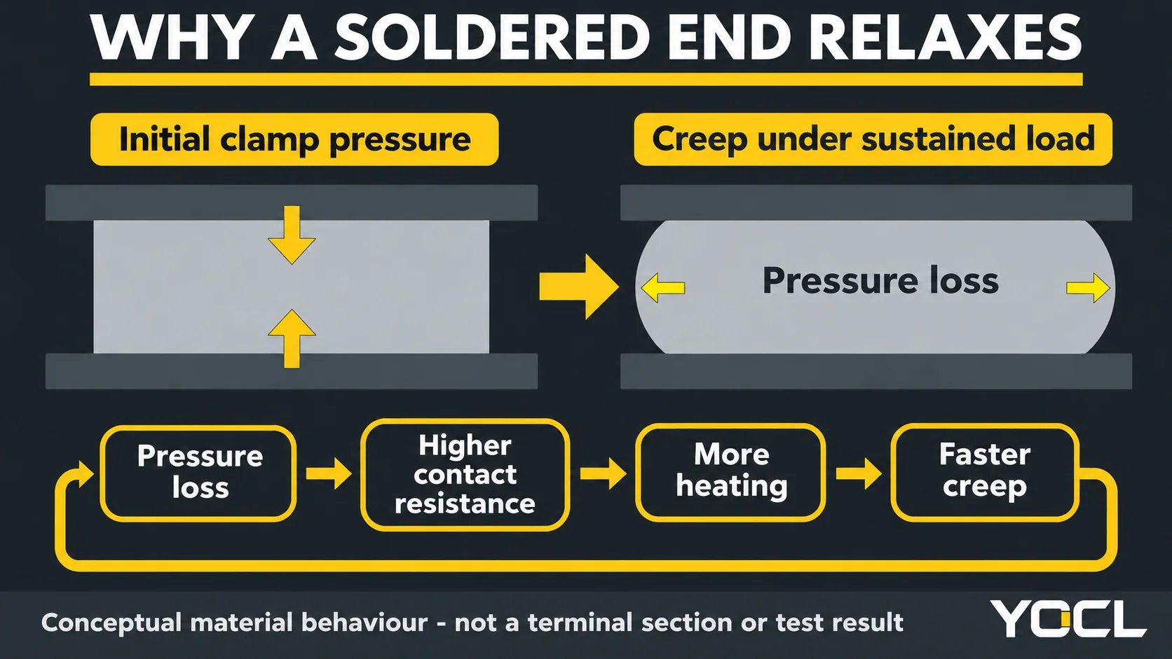
The table describes a mechanism, not a guaranteed timeline or a diagnosis from a stain. An overheated terminal may have other causes, and a soldered end may look acceptable while its contact condition is already deteriorating. Neither continued operation nor a clean exterior demonstrates long-term suitability.
What the rules actually say
NFPA 79 is the US Electrical Standard for Industrial Machinery. It provides an explicit reference for this discussion; it is not being presented as mandatory law in every YOCL customer market. The quotations below were checked against publicly reproduced text of the 2015 edition. The project must use its applicable adopted requirements and equipment instructions. [4]
Section 13.1.1.5 states:
“Soldered connections shall only be permitted where terminals are provided that are identified for soldering.”
Section 13.1.1.8 requires a means of retaining conductor strands when the device or terminal does not provide that facility. Its concluding sentence is explicit:
“Solder shall not be used for that purpose.”
Read these as separate points: a genuine soldered connection needs a terminal intended for soldering, and solder is not a substitute for required strand retention at an ordinary pressure terminal. A component having solder pins for attachment to a circuit board does not establish that its separate wire clamp accepts a solder-dipped conductor.
The practical question is therefore documentary: does the exact conductor connection expressly accept the soldered preparation? An unspecified exception for soldering somewhere on a component is insufficient. If the connection is a normal pressure clamp with no such permission, keep solder out of the clamped stranded end.
Manufacturer instructions can be more immediately useful than an argument about workshop custom. The inspected Woodward and TOA manuals expressly prohibit tinning at their specified terminals. A habitual preparation should be changed to follow the written connection requirements; habit does not resolve a mismatch between the wire end and the clamp. [1, 3]
Screw vs spring vs push-in: compensation is not permission
Screw clamps
An ordinary screw connection establishes preload through the screw and clamping structure. If the solder beneath it deforms, the original tightening operation does not automatically restore the lost preload. This is why a solder-bound end is a poor substitute for the wire preparation the clamp was designed to accept.
Do not assume every screw acts directly on strands: a pressure plate or cage may intervene. Some engineered assemblies also have elastic features. Those details change force transmission, but they do not create permission to add solder. The exact terminal’s conductor instructions remain the controlling evidence.
Spring clamps
A spring can follow some conductor movement and maintain force within its designed working travel. That makes its response different from a fixed screw adjustment. It does not prove that the spring has sufficient travel, contact geometry or acceptance for a solder-consolidated end.
The distinction is documented, not just theoretical. Woodward’s spring-loaded terminal instructions also prohibit tinning: those terminals are intended to flatten the strands, and bonding them together changes the intended contact. A spring may compensate for movement while still being the wrong connection for that prepared end. [5]
Push-in and lever-operated entries
These names describe an insertion or opening action, not an exemption from conductor requirements. A direct-insertion terminal may accept particular solid or ferruled ends; a lever may open a spring for a different preparation. Neither permits stiffening an otherwise unsuitable flexible conductor with solder merely to make it enter.
For the wider mechanism and workflow comparison, use screw vs spring terminal blocks. Here the narrower decision is unchanged across the three entries: no solder tip unless the exact connection expressly permits it.
What to do instead
Choose a conductor treatment from the receiving terminal’s accepted configurations. Bare strands, a crimped ferrule and a ring or fork terminal solve different interface problems; they are not interchangeable upgrades.
| Forma de conexión | Appropriate route when documented | What the document must settle |
|---|---|---|
| DIN rail screw or spring block with strand retention | Bare stranded conductor | Accepted conductor construction and the terminal’s preparation/insertion instructions |
| DIN rail block accepting ferruled conductors | A properly selected and crimped bootlace ferrule | Permitted prepared-end geometry and conductor combination, plus the matching ferrule/tool process |
| Bare-screw or barrier-strip connection intended for terminal tongues | A compatible crimped ring or fork terminal | Permitted tongue shape, screw interface and assembly instructions |
A bootlace ferrule mechanically consolidates strands inside a metal sleeve through crimping. It does not replace the strands with a soft solder-filled plug. That distinction explains the alternative, but it does not make every ferrule or crimp acceptable in every block. Sleeve geometry, finished profile and the terminal’s accepted preparation still matter.
For a bare-screw or barrier-strip connection intended to receive a ring or fork, use that documented interface. A ferrule forced beneath an unsuitable screw does not become correct because it was solderless. Conversely, do not assume every barrier terminal excludes bare wire: the terminal’s actual construction and instructions decide the permitted route.
de YOCL DIN rail terminal-block category y wire-ferrule category are document-review starting points. Identify the exact receiving terminal, then confirm which prepared ends it accepts. These category links do not establish solder-tip acceptance, certification or a matched terminal/ferrule combination.
Where a ferrule is permitted, follow the separate wire-ferrule crimping guide and the exact process instructions. Adding solder before or after crimping is not an improvised substitute for a controlled crimp. When the required compatibility information is unavailable, obtain it rather than choosing a preparation by appearance.
Found tinned ends in service?
A fused soldered tip, repeated loss of clamping condition or local heat discolouration deserves investigation. None is a reason to touch or tighten an energized connection. Have a qualified person isolate the equipment and verify it is deenergized under the applicable procedure before examining or remaking the termination.
Retightening alone does not remove the solder or its creep mechanism. It can temporarily restore pressure while leaving the material that caused pressure loss inside the clamp. A recurring maintenance adjustment is not a substitute for correcting an unapproved prepared end.
After isolation, the correction is to remove the solder-bound portion and remake the connection using a permitted preparation. Solder can wick between strands beyond the visibly dipped tip, so the cut must reach sound, flexible conductor free of solder consolidation. Do not simply trim the shiny end and assume everything behind it is unchanged.
If reaching clean flexible conductor leaves insufficient cable for the documented termination, stop and resolve the conductor replacement or routing requirement. Do not stretch a shortened conductor into position. Inspect the receiving clamp and nearby insulation too: remaking the wire end does not restore a heat-damaged terminal.
Wicking also creates a transition between a rigid region and a flexible wire. Movement can concentrate stress where that rigid region ends, encouraging fatigue failure. NASA’s harness workmanship guidance describes this effect for solder-dipped conductors; the mechanism supports checking beyond the visible tip, not importing spacecraft assembly requirements into an industrial panel. [6]
Record the original end condition, the receiving terminal identity and the preparation used for the remake. Before return to service, complete the equipment’s prescribed connection checks. For other possible heating causes and the wider inspection process, see terminal-block overheating checks; this article addresses the solder-tip mechanism specifically.
Preguntas frecuentes
Is it OK if I only tin the very tip of the strands?
Only if the clamp bears wholly on the untinned conductor behind that tip, the solder does not interfere with insertion or the required flexible region, and the terminal instructions permit the completed arrangement. Do not assume those conditions from the visible tip length: solder can wick farther back. For an ordinary unapproved solder-ended preparation, remove the affected portion and remake it.
Is factory tinned marine wire the same thing?
No. Factory tinned-copper wire has individually plated strands, not strands soldered together into one end. It remains a different conductor construction from a solder-dipped tip. That distinction does not approve it for every terminal; confirm that the exact terminal accepts its material, strand construction and preparation.
Can I just re-torque tinned ends on a maintenance schedule?
No. Retightening can restore pressure temporarily but leaves solder in the clamped region, where deformation can continue. It does not correct an unapproved termination. After isolation and verification, remove the solder-affected portion, assess any damage and remake the connection using an accepted preparation and the equipment’s instructions.
Do spring terminals make a soldered tip safe?
Not by themselves. A spring can maintain force over a designed range of movement, but the terminal still needs to accept the actual prepared end. Bonded strands may defeat its intended contact geometry. Unless the exact conductor connection expressly permits soldered ends, use the documented bare or ferruled preparation instead.
What should I put on stranded wire instead of solder?
Use the preparation specified for the receiving terminal: bare strands where its retention structure accepts them, a compatible crimped bootlace ferrule where permitted, or a crimped ring/fork for a connection intended for that tongue. The terminal, conductor and finished termination must match; no single treatment is correct for every clamp.
Fuentes
- Woodward, ProTech-GII Manual 26545, Revision G, October 2020, printed p. 33. Equipment-specific cold-flow warning and distinction between solder-bound and individually plated strands.
- NREL / US Department of Energy, Thermal Performance and Reliability of Bonded Interfaces, Douglas DeVoto, May 15, 2012, slide 9. Qualitative solder-creep mechanism; no terminal test results transferred.
- TOA, IP-A1PG Instruction Manual, section 9.4, p. 12. Soldered-end pressure, contact-resistance and heating warning for its supplied terminals.
- NFPA 79, publicly reproduced 2015 text, sections 13.1.1.5 and 13.1.1.8. Supplied quotations cross-checked; not a claim about the latest adopted local edition.
- Woodward, 2301E-J Manual 26818, Revision A, printed p. 36. Explicit no-tinning instruction for its spring-loaded terminals.
- NASA, NASA-STD-8739.4A with Change 4, section 13.3.1. Solder-wicking stiffness transition and conductor fatigue; limited workmanship context.
- YOCL ELECTRIC, DIN rail terminal-block and wire-ferrule category pages linked above, checked November 10, 2026. First-party catalogue routing only; no certification or solder-tip approval inferred.