YOCL

Barrette d'alimentation
Fabricant

Barrettes d'alimentation pour la distribution d'énergie des disjoncteurs, avec connexions à broche, fourche et type U dans les séries 1P–4P. Explorez les barrettes de connexion en cuivre C45, DPN et spécifiques à l'équipement, puis faites correspondre le modèle complet aux bornes de votre appareil et aux exigences de votre panneau.

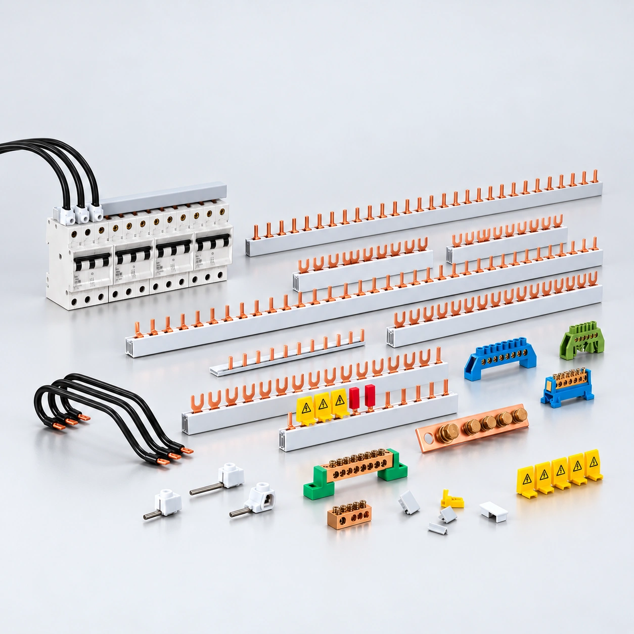
YOCL pin and fork comb busbar collection with distribution accessories

Gamme de barrettes d'alimentation

Ouvrir le catalogue complet

Explorez tous les types de connexion. Vérifiez les dimensions de chaque modèle et les exigences de l'appareil récepteur avant de commander.

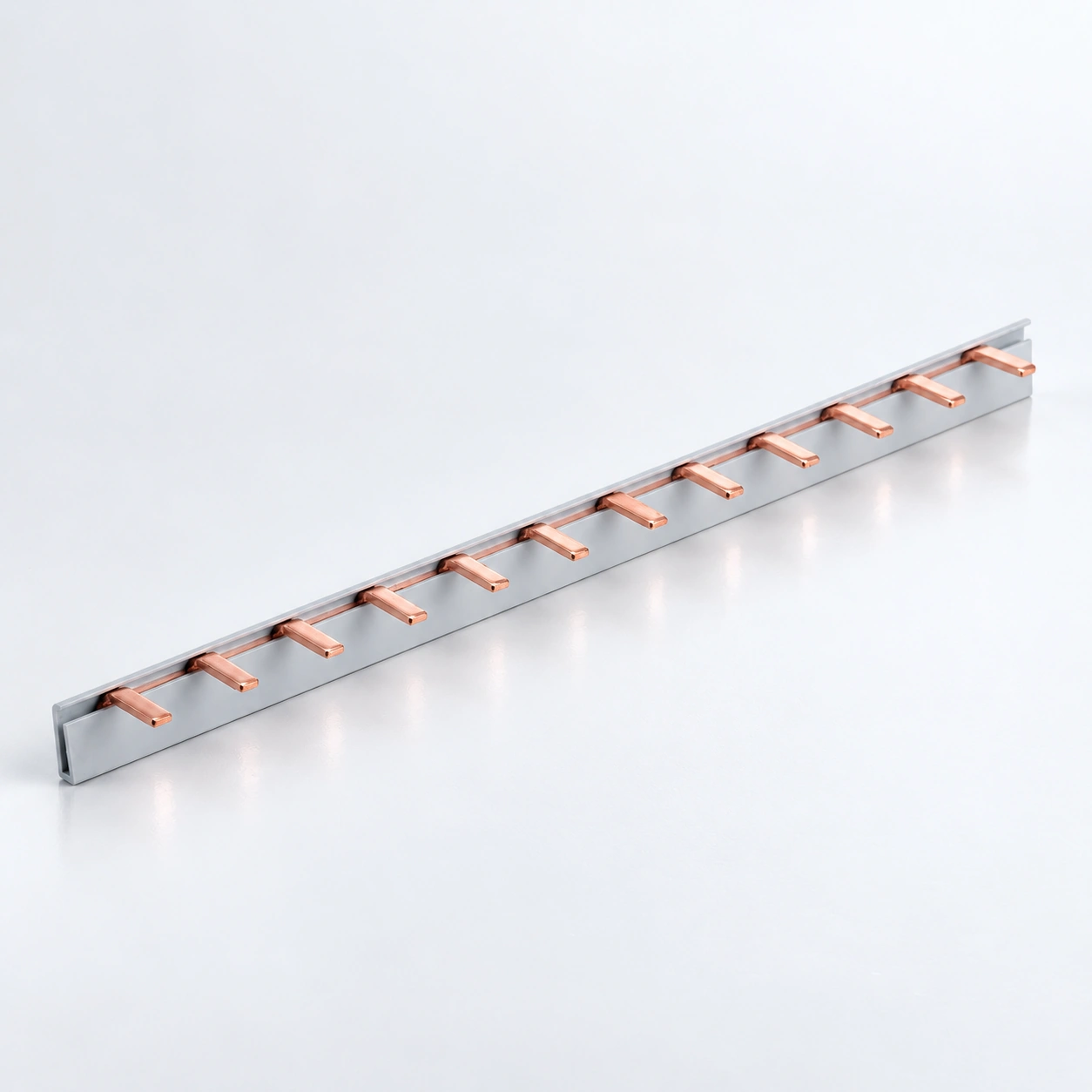
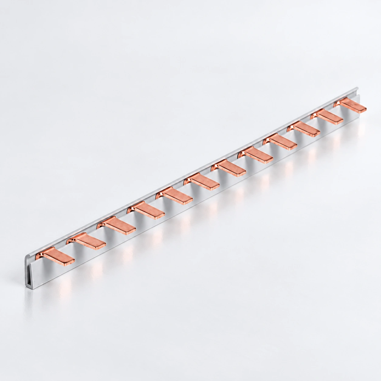
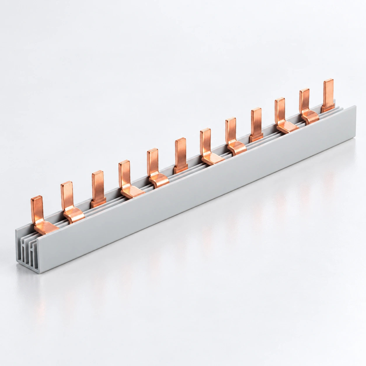
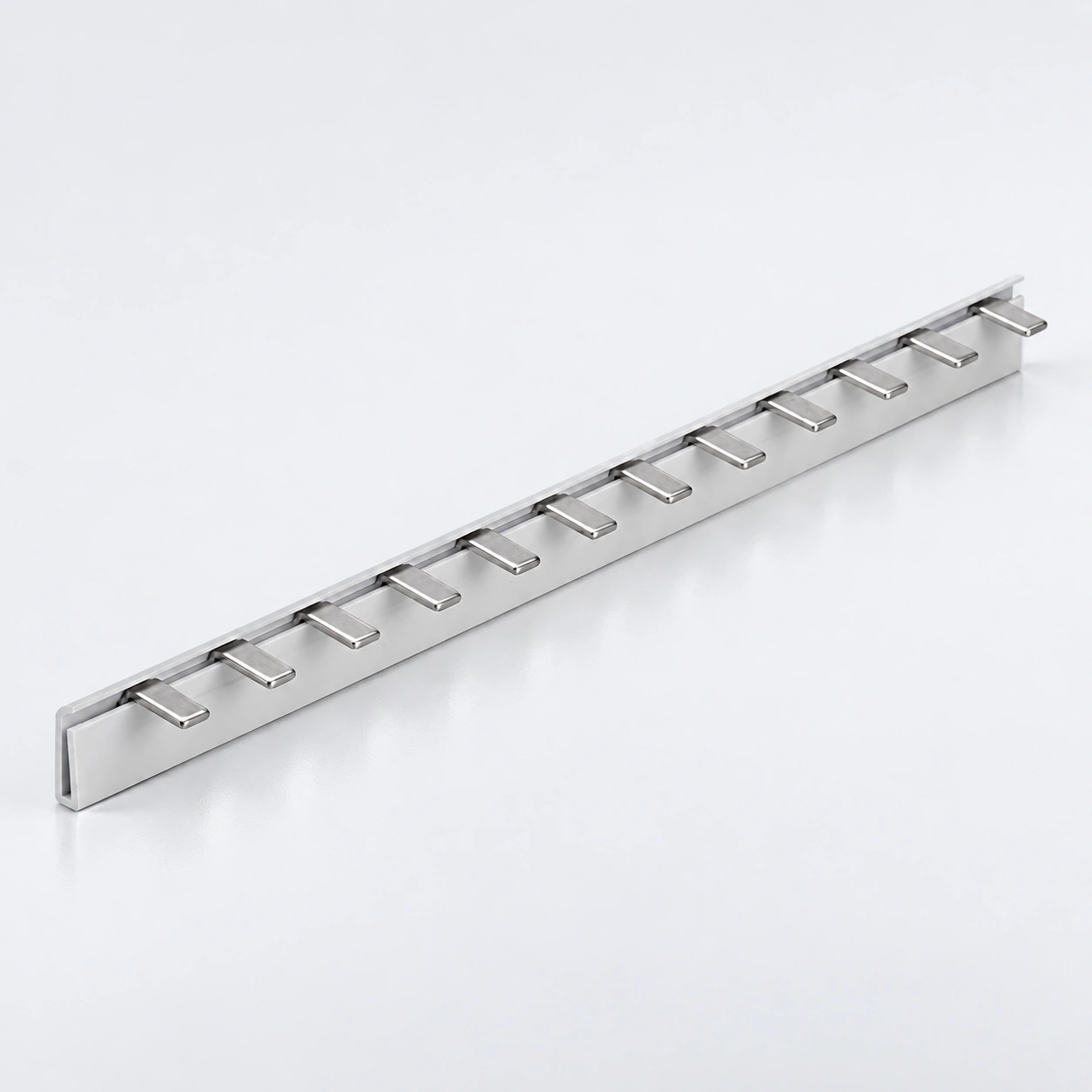
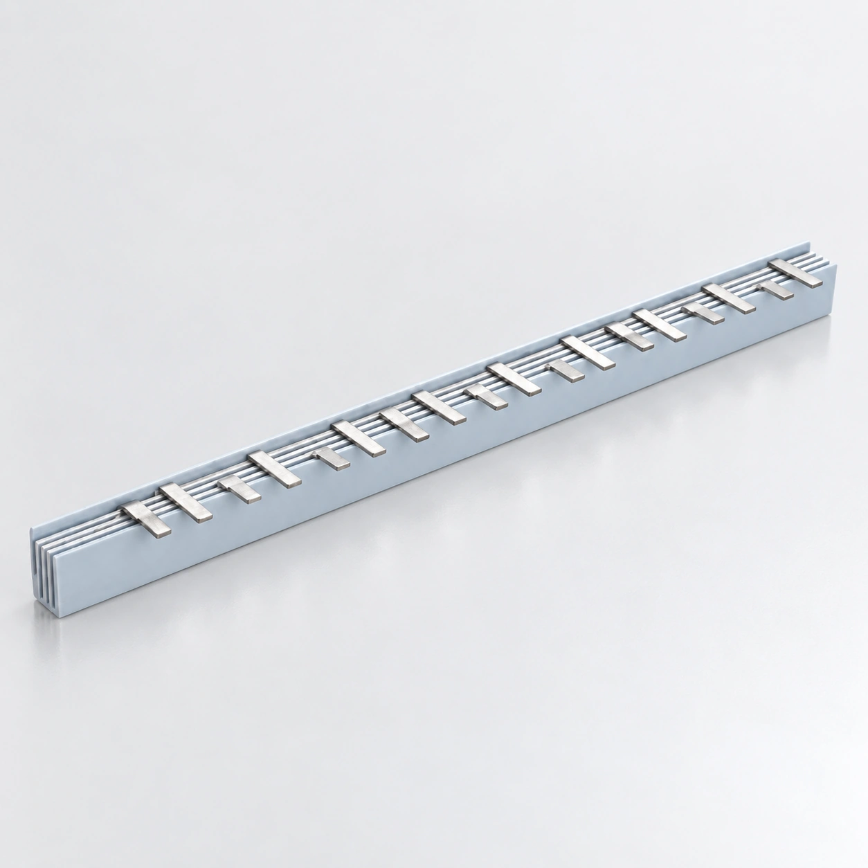
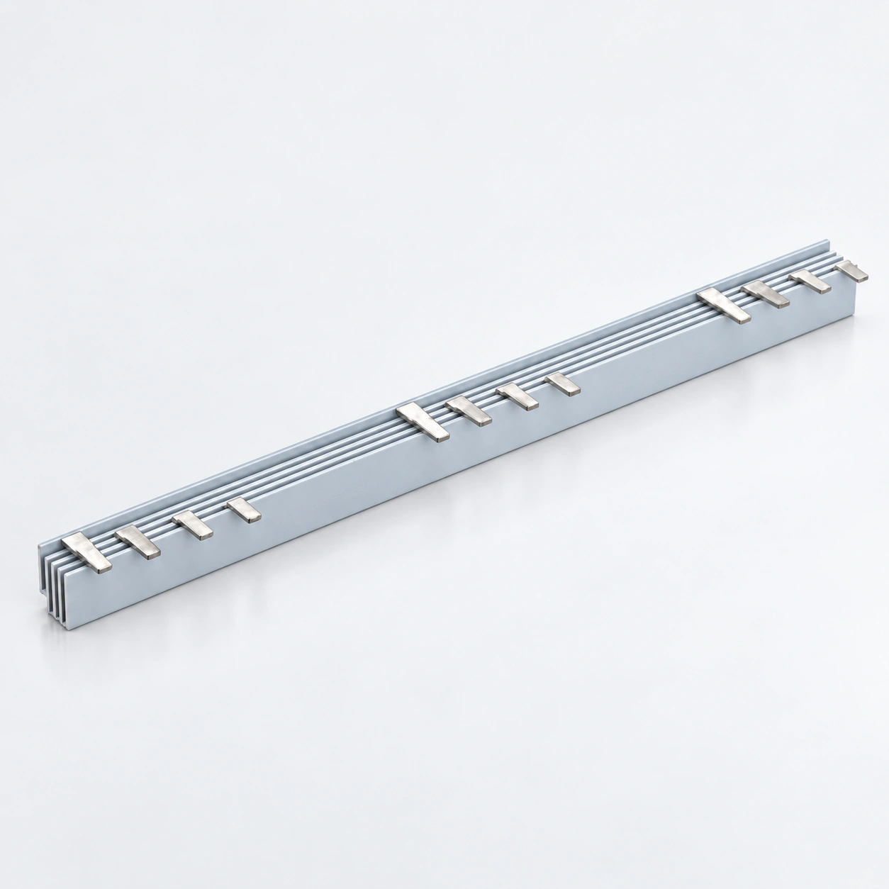
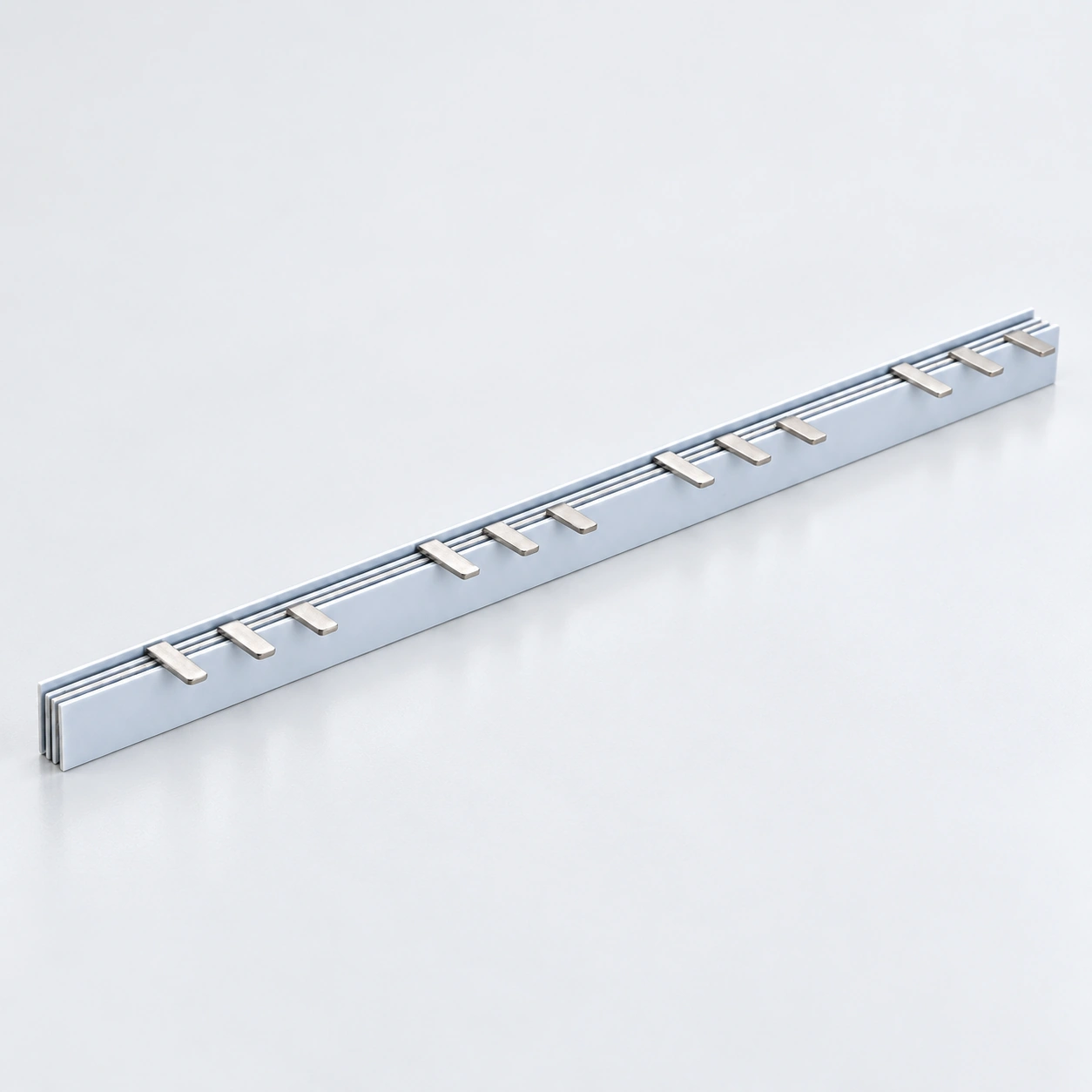
Barres omnibus à broches MCB série BS101 1P

Barres omnibus à broches MCB série BS101 1P

Configuration
broche 1P
Cuivre
6–16 mm²
Courant nominal
40–80 A
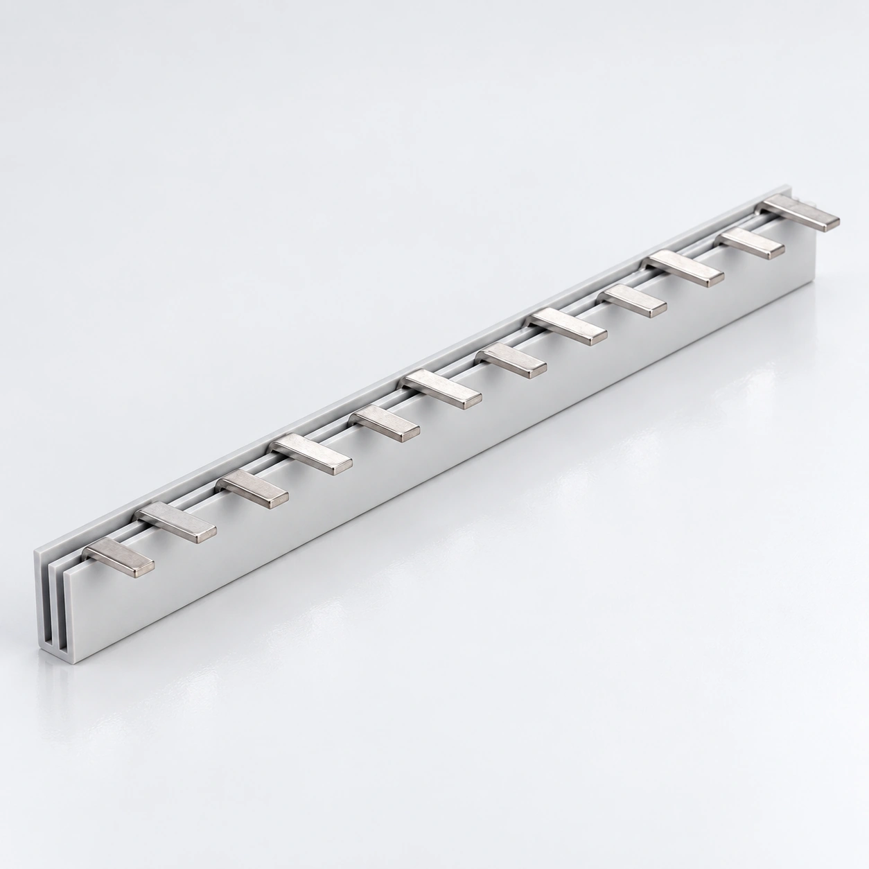
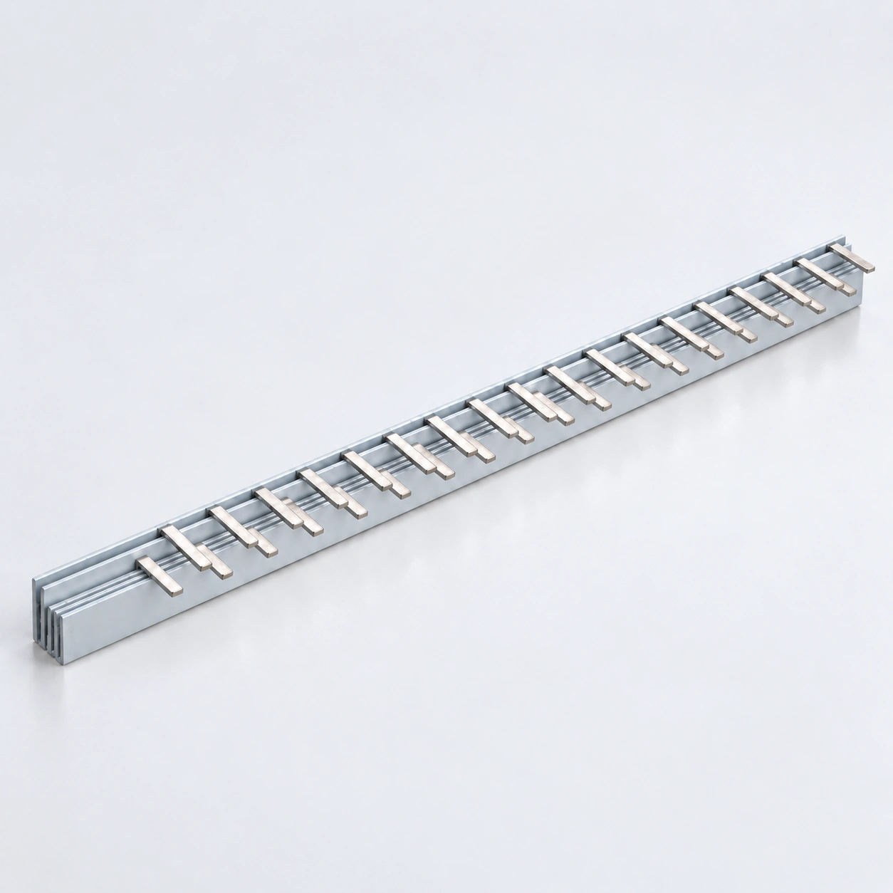
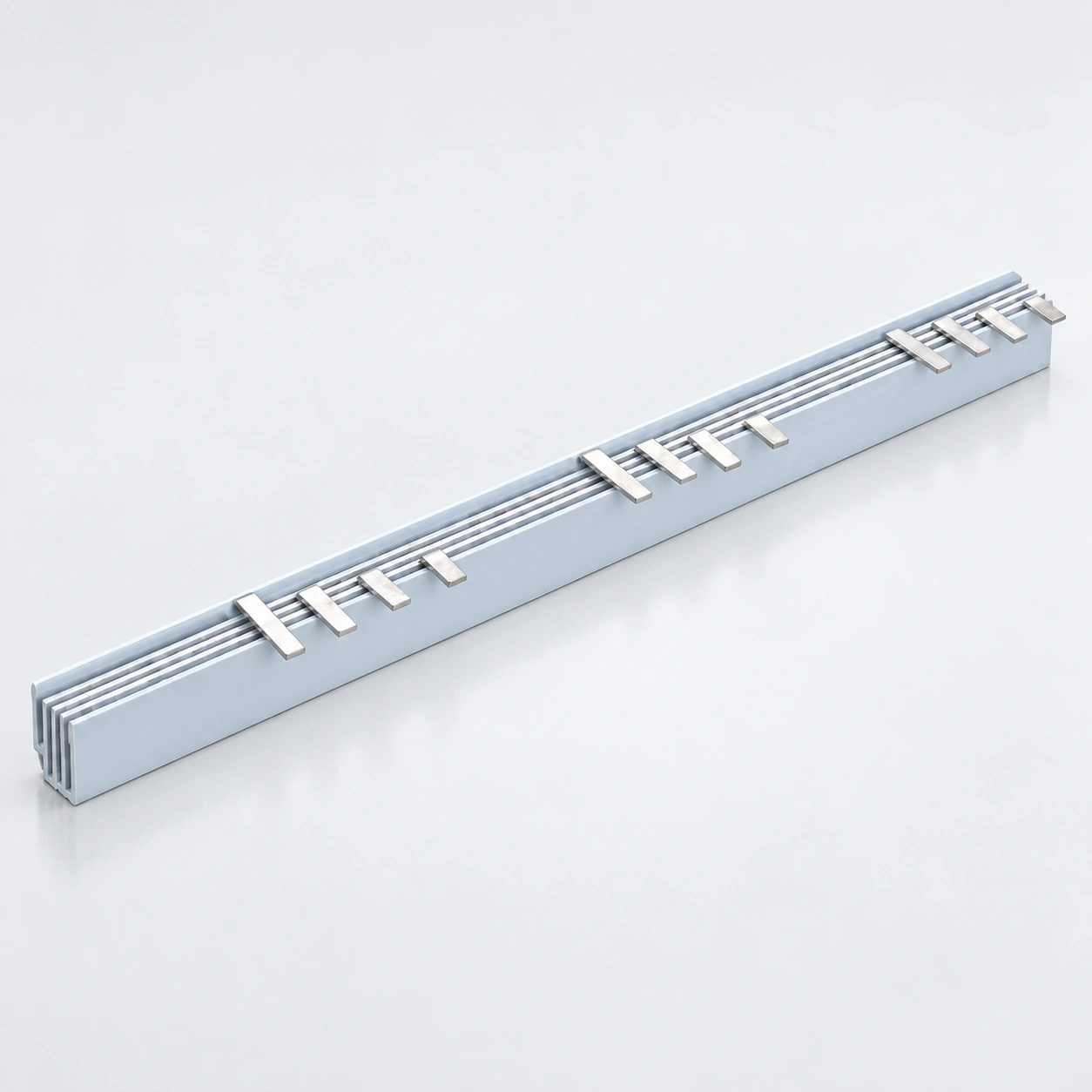
Barres omnibus à broches MCB série BS102 2P

Barres omnibus à broches MCB série BS102 2P

Configuration
broche 2P
Cuivre
6–16 mm²
Courant nominal
40–80 A
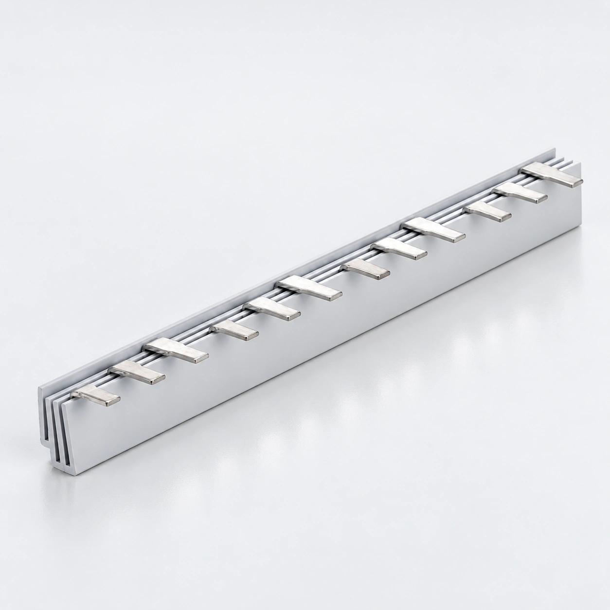
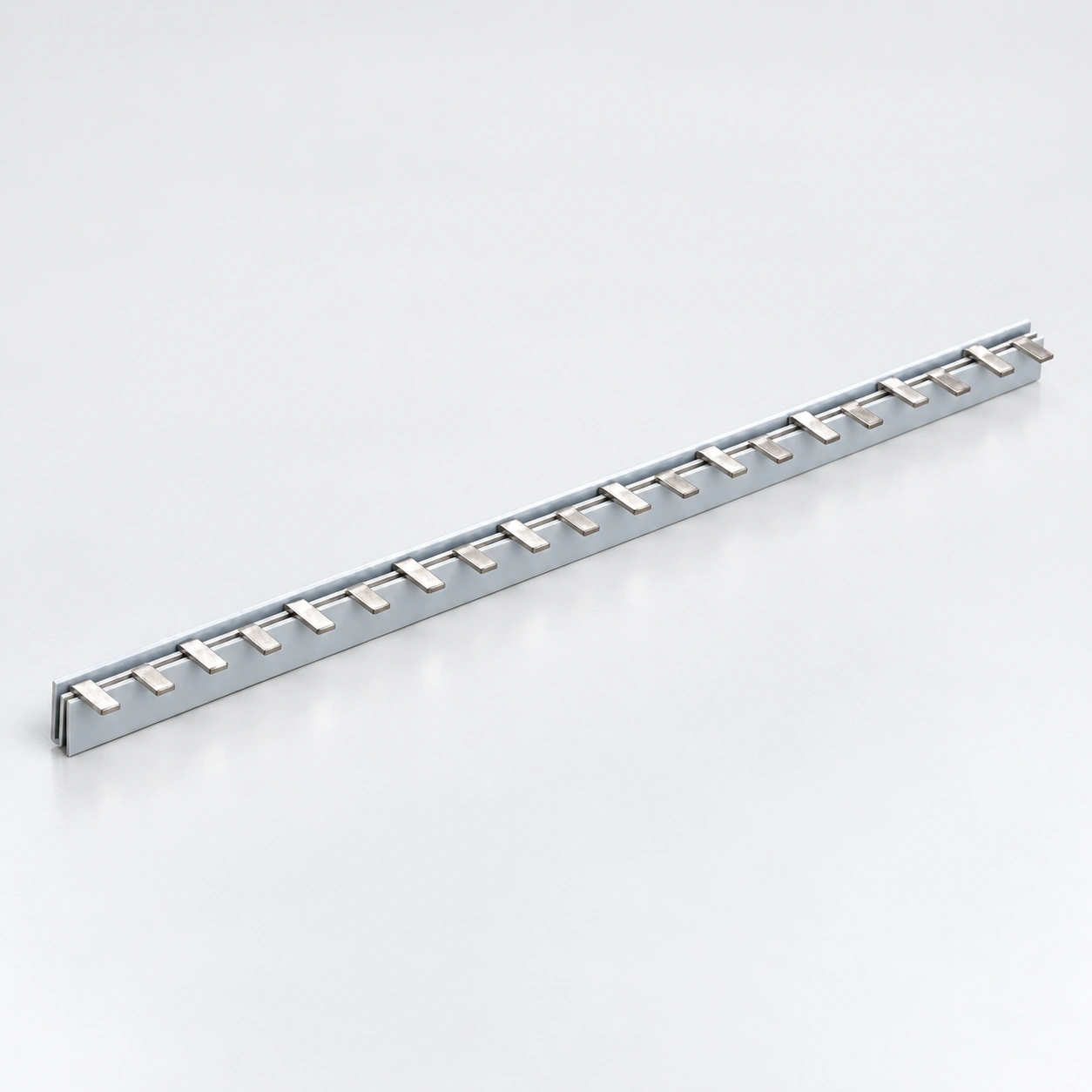
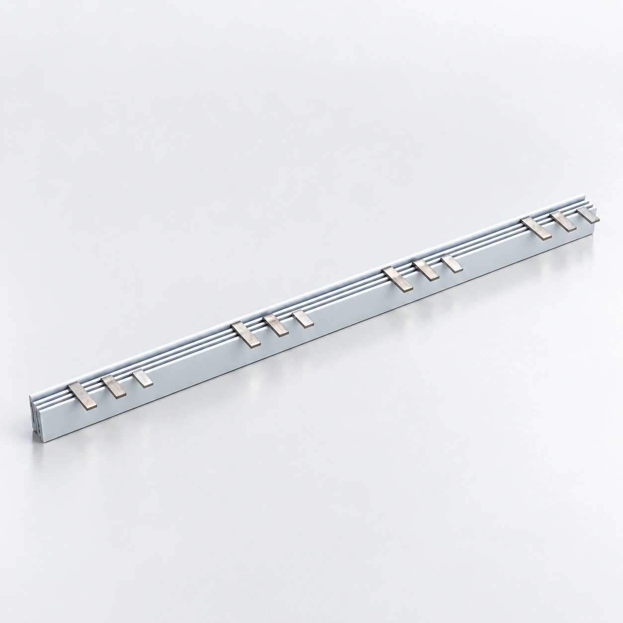
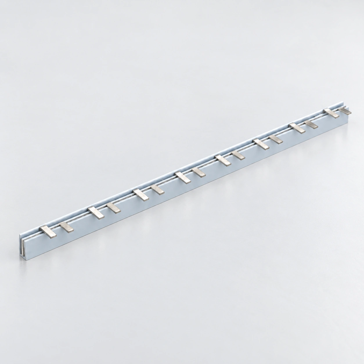
Barres omnibus à broches MCB série BS103 3P

Barres omnibus à broches MCB série BS103 3P

Configuration
broche 3P
Cuivre
6–16 mm²
Courant nominal
40–80 A
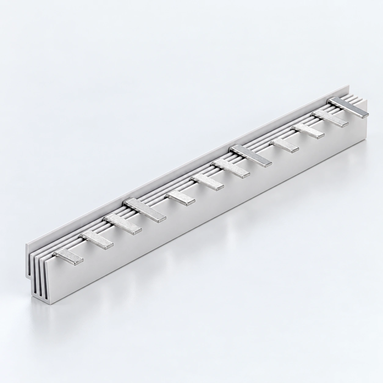
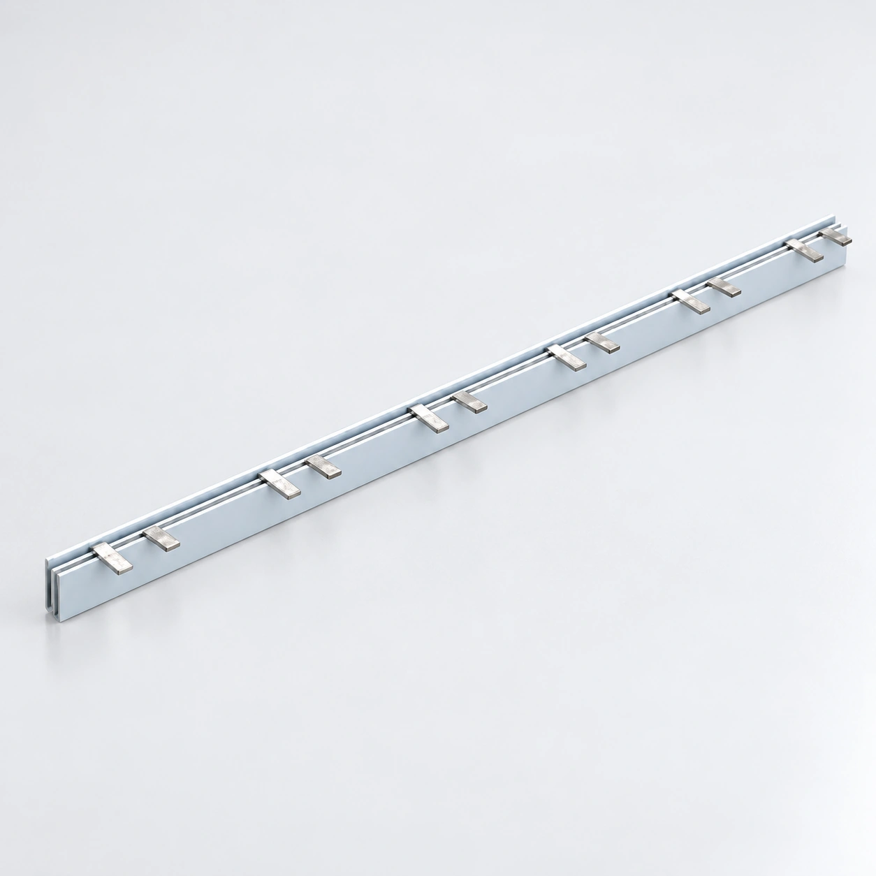
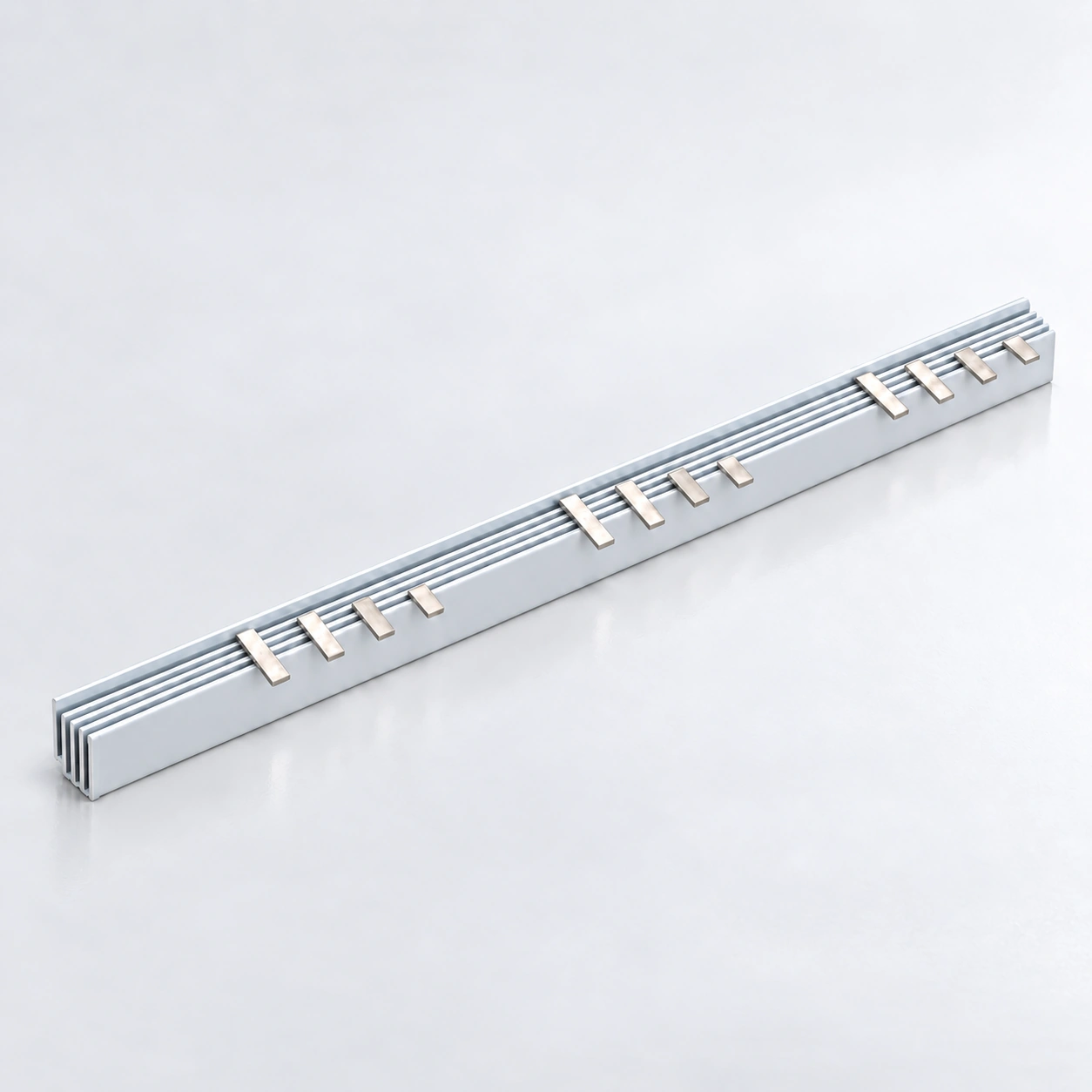
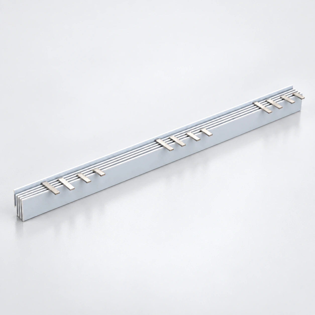
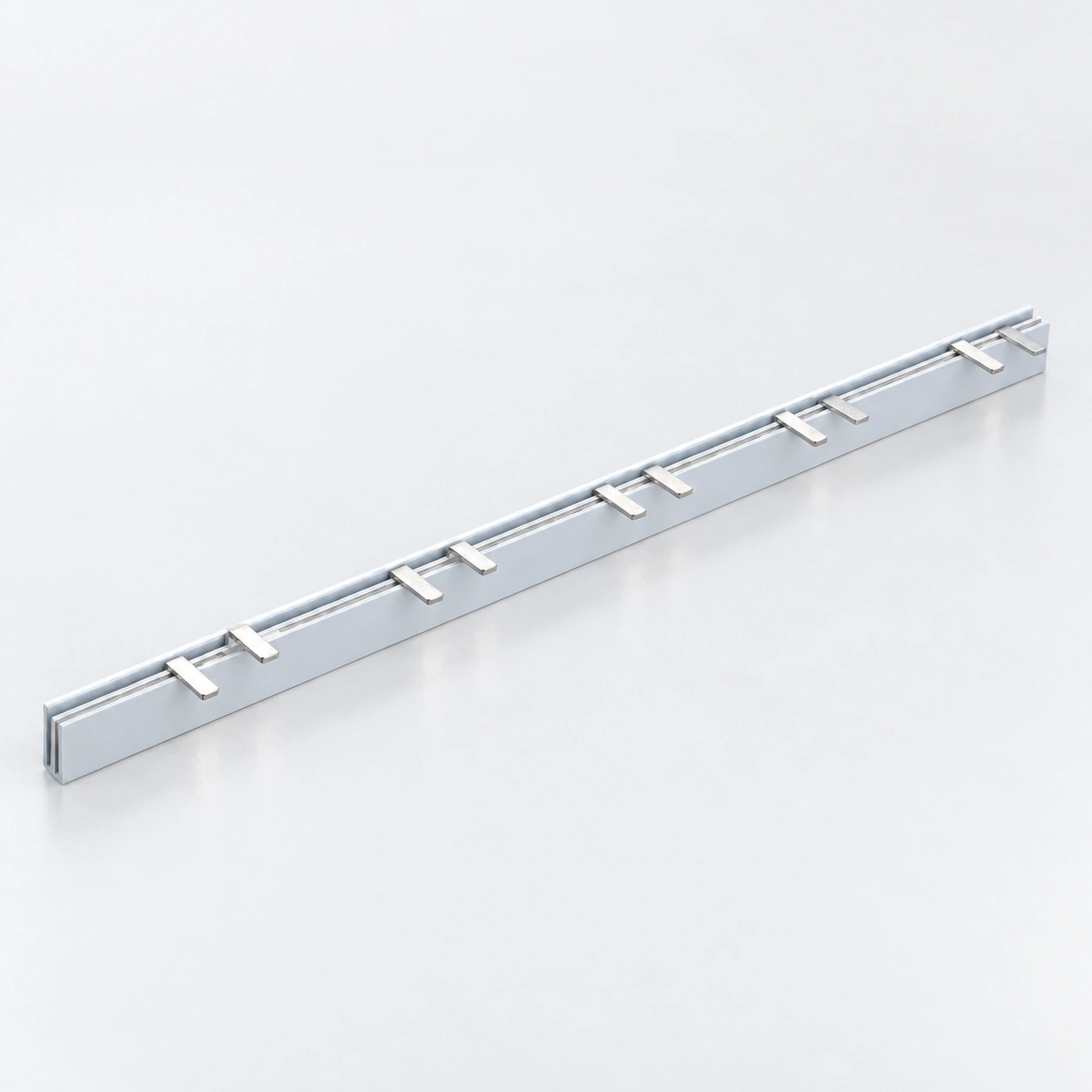
Barres omnibus à broches MCB série BS104 4P

Barres omnibus à broches MCB série BS104 4P

Configuration
broche 4P
Cuivre
6–16 mm²
Courant nominal
40–80 A
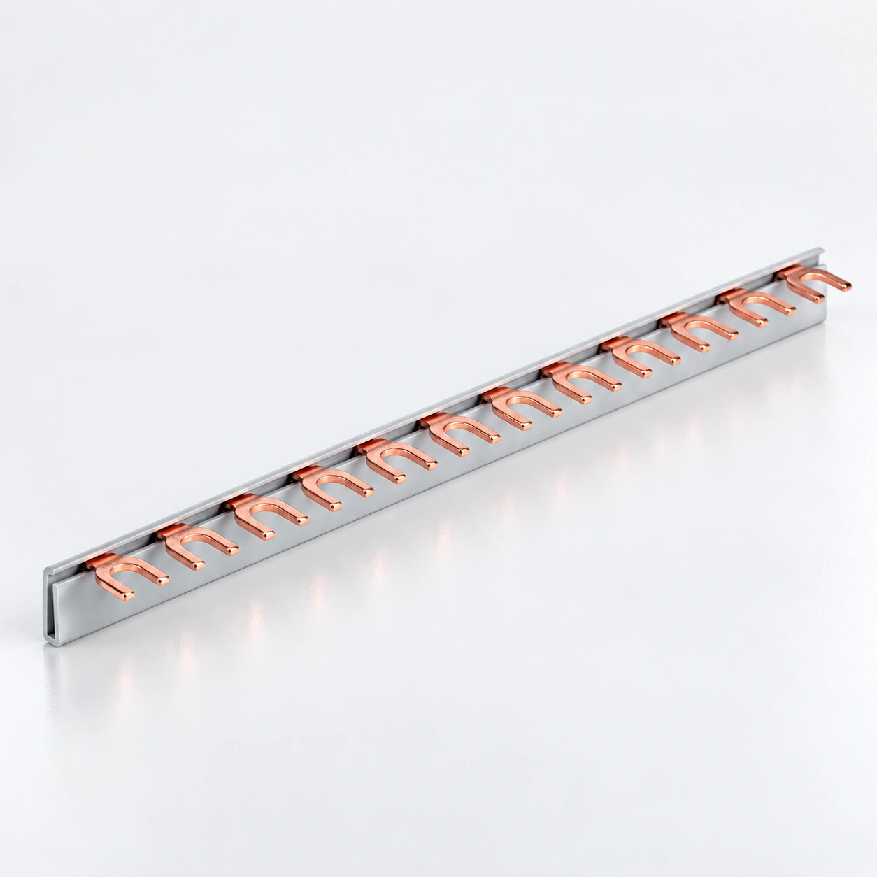
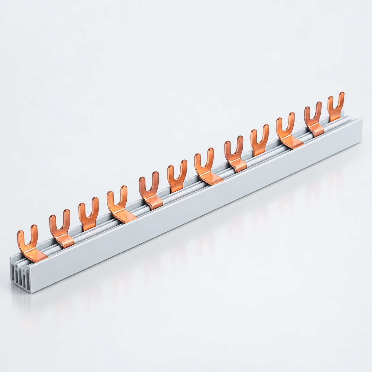
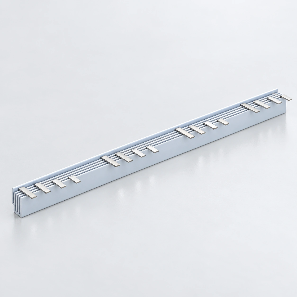
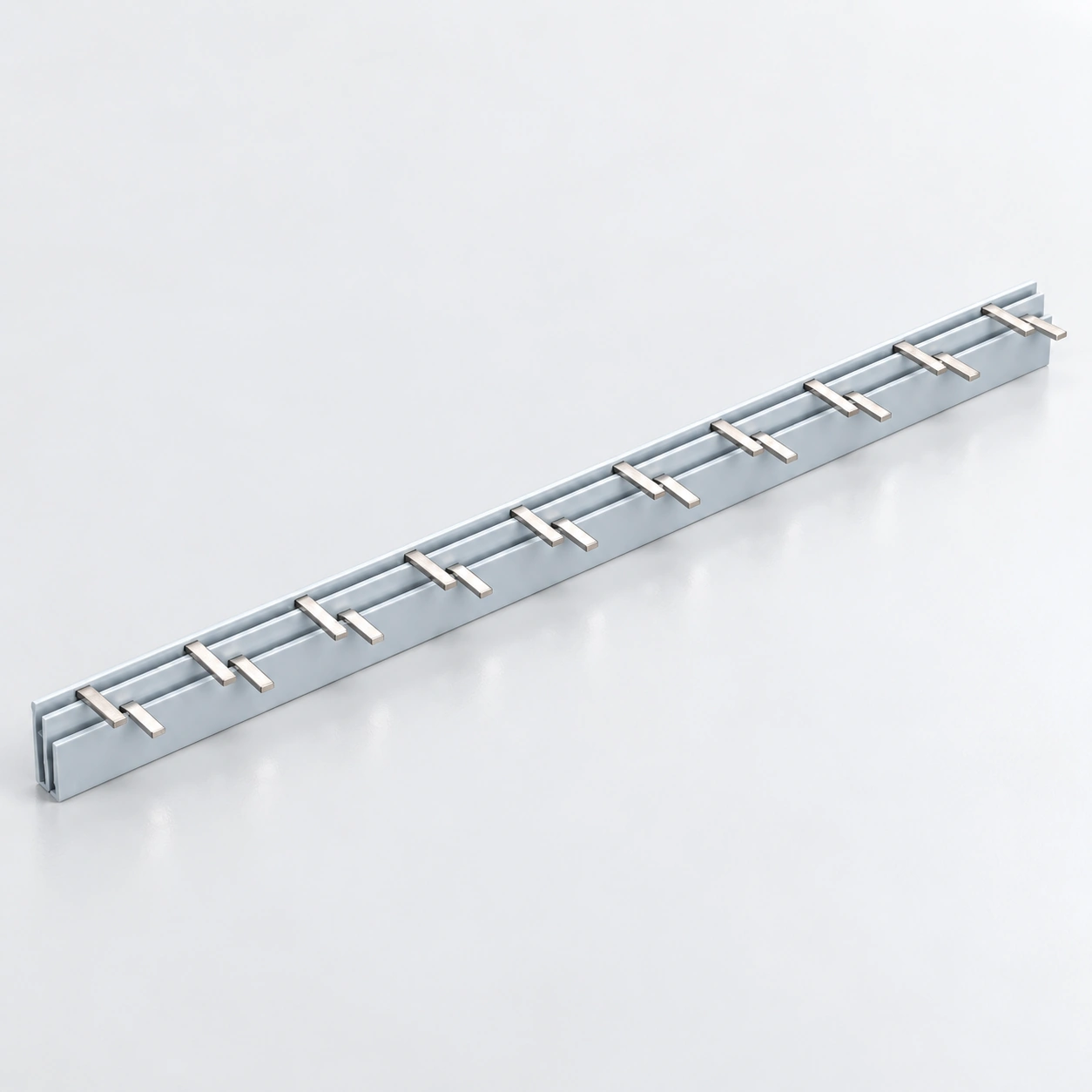
Barres omnibus à fourche MCB série BS201 1P C45

Barres omnibus à fourche MCB série BS201 1P C45

Configuration
fourche (C45) 1P
Cuivre
6–16 mm²
Courant nominal
40–80 A
Barres omnibus à fourche MCB série BS202 2P C45

Barres omnibus à fourche MCB série BS202 2P C45

Configuration
fourche (C45) 2P
Cuivre
6–16 mm²
Courant nominal
40–80 A
Série BS203 3P Barres omnibus à fourche pour disjoncteurs miniatures C45

Série BS203 3P Barres omnibus à fourche pour disjoncteurs miniatures C45

Configuration
fourche (C45) 3P
Cuivre
6–16 mm²
Courant nominal
40–80 A
Barres omnibus pour disjoncteurs BS204 Série 4P C45 Fourche MCB

Barres omnibus pour disjoncteurs BS204 Série 4P C45 Fourche MCB

Configuration
fourche (C45) 4P
Cuivre
6–16 mm²
Courant nominal
40–80 A
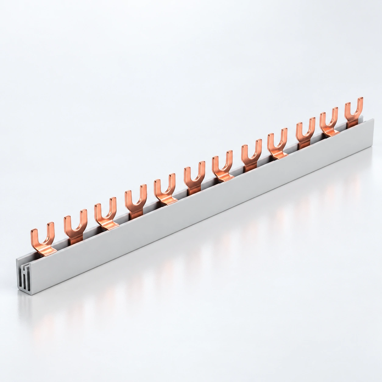
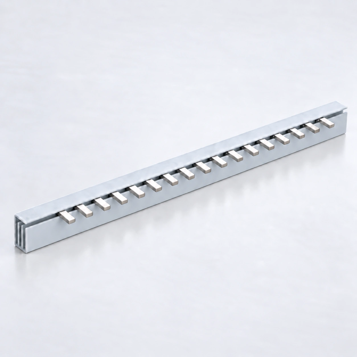
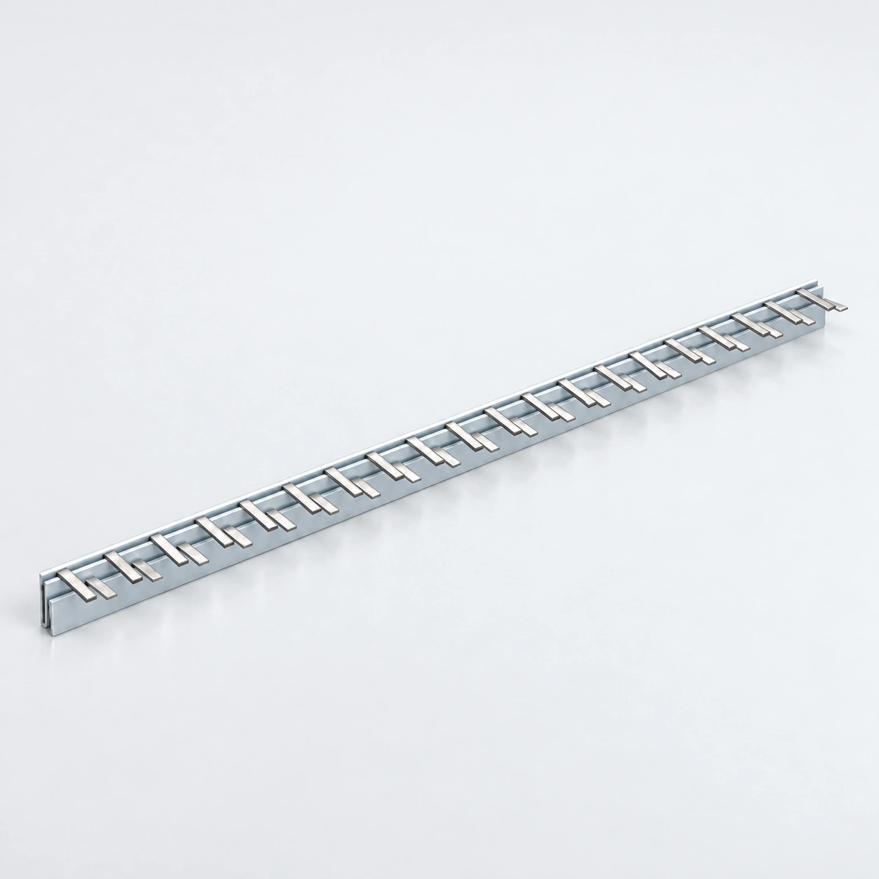
Barres omnibus MCB type U série BS301 1P

Barres omnibus MCB type U série BS301 1P

Configuration
type U 1P
Cuivre
6–16 mm²
Courant nominal
40–80 A
BS302 Série 2P Barres omnibus pour disjoncteurs modulaires de type U

BS302 Série 2P Barres omnibus pour disjoncteurs modulaires de type U

Configuration
type U 2P
Cuivre
6–16 mm²
Courant nominal
40–80 A
Barres omnibus MCB type U série BS303 3P

Barres omnibus MCB type U série BS303 3P

Configuration
type U 3P
Cuivre
6–16 mm²
Courant nominal
40–80 A
Barres omnibus pour disjoncteurs miniatures type U série BS304 4P

Barres omnibus pour disjoncteurs miniatures type U série BS304 4P

Configuration
Type U 4P
Cuivre
6–16 mm²
Courant nominal
40–80 A
Barres omnibus pour disjoncteurs BS201D Série 1P C45 MCB

Barres omnibus pour disjoncteurs BS201D Série 1P C45 MCB

Configuration
C45 1P
Cuivre
6–16 mm²
Courant nominal
32–100 A
Barres omnibus pour disjoncteurs BS202D Série 2P C45 MCB

Barres omnibus pour disjoncteurs BS202D Série 2P C45 MCB

Configuration
C45 2P
Cuivre
6–16 mm²
Courant nominal
32–100 A
Barres omnibus pour disjoncteurs BS203D Série 3P C45 MCB

Barres omnibus pour disjoncteurs BS203D Série 3P C45 MCB

Configuration
C45 3P
Cuivre
6–18 mm²
Courant nominal
32–100 A
Barres omnibus pour disjoncteurs miniatures série BS204D 4P C45

Barres omnibus pour disjoncteurs miniatures série BS204D 4P C45

Configuration
C45 4P
Cuivre
6–16 mm²
Courant nominal
40–80 A
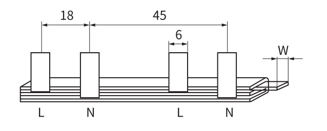
BS2P-1 2P Barre omnibus triphasée en cuivre

BS2P-1 2P Barre omnibus triphasée en cuivre

Configuration
2P Triphasé
Cuivre
10 mm²
Courant nominal
63 A
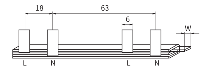
BS3P-1P+N en Cuivre pour Disjoncteur DPN 3

BS3P-1P+N en Cuivre pour Disjoncteur DPN 3

Configuration
DPN 3P+N
Cuivre
10 mm²
Courant nominal
63 A
BS401 C451P-L en Cuivre pour Disjoncteur

BS401 C451P-L en Cuivre pour Disjoncteur

Configuration
C451P-L
Cuivre
6–13 mm²
Courant nominal
32–63 A
BS402 C452P-L Barres omnibus MCB en cuivre

BS402 C452P-L Barres omnibus MCB en cuivre

Configuration
C452P-L
Cuivre
6–13 mm²
Courant nominal
32–70 A
BS403 C453P-L Barres omnibus MCB en cuivre

BS403 C453P-L Barres omnibus MCB en cuivre

Configuration
C453P-L
Cuivre
6–13 mm²
Courant nominal
40–70 A
BS404 3P 2 Barres omnibus MCB en cuivre

BS404 3P 2 Barres omnibus MCB en cuivre

Configuration
3P 2
Cuivre
10–13 mm²
Courant nominal
63–150 A
BS404 C454P-L Barres omnibus MCB en cuivre

BS404 C454P-L Barres omnibus MCB en cuivre

Configuration
C454P-L
Cuivre
10–13 mm²
Courant nominal
63–70 A
BS404-1 3 PNC DZ158 Barres omnibus MCB en cuivre

BS404-1 3 PNC DZ158 Barres omnibus MCB en cuivre

Configuration
3 PNC DZ158
Cuivre
13 mm²
Courant nominal
100 A
BS404-1 4Peigne de raccordement en cuivre pour disjoncteur modulaire PLE

BS404-1 4Peigne de raccordement en cuivre pour disjoncteur modulaire PLE

Configuration
4PLE
Cuivre
10 mm²
Courant nominal
63 A
BS404-1 DZ158 NC100 4Peigne de raccordement en cuivre pour disjoncteur modulaire PNC

BS404-1 DZ158 NC100 4Peigne de raccordement en cuivre pour disjoncteur modulaire PNC

Configuration
DZ158 NC100 4PNC
Cuivre
13 mm²
Courant nominal
100 A
BS501LE C651P-LE Barres omnibus MCB en cuivre

BS501LE C651P-LE Barres omnibus MCB en cuivre

Configuration
C651P-LE
Cuivre
6–13 mm²
Courant nominal
40–70 A
BS502 C652P-LE Barres omnibus en cuivre pour disjoncteurs miniatures

BS502 C652P-LE Barres omnibus en cuivre pour disjoncteurs miniatures

Configuration
C652P-LE
Cuivre
10–13 mm²
Courant nominal
63–70 A
BS503 C653P-LE Barres omnibus MCB en cuivre

BS503 C653P-LE Barres omnibus MCB en cuivre

Configuration
C653P-LE
Cuivre
6–13 mm²
Courant nominal
40–70 A
BS504 C654P-LE Barres omnibus en cuivre pour disjoncteurs miniatures

BS504 C654P-LE Barres omnibus en cuivre pour disjoncteurs miniatures

Configuration
C654P-LE
Cuivre
6–13 mm²
Courant nominal
40–70 A
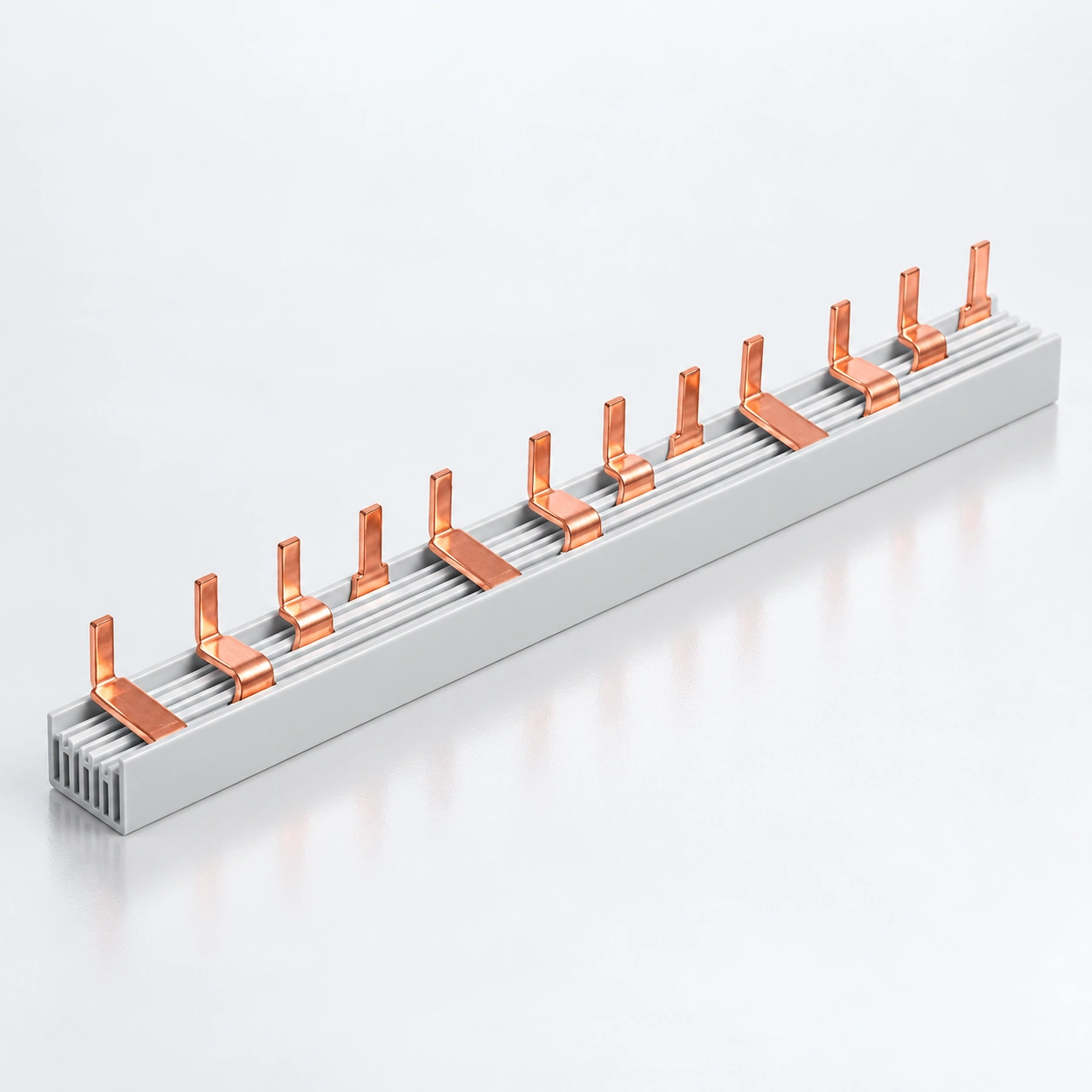
BS601 Peignes de raccordement en cuivre pour disjoncteur modulaire DPN

BS601 Peignes de raccordement en cuivre pour disjoncteur modulaire DPN

Configuration
DPN
Cuivre
6–13 mm²
Courant nominal
32–70 A
BS602 Barres omnibus DPNLE en cuivre MCB

BS602 Barres omnibus DPNLE en cuivre MCB

Configuration
DPNLE
Cuivre
6–13 mm²
Courant nominal
32–70 A
BS808 AC CJX2 Barrette omnibus en cuivre

BS808 AC CJX2 Barrette omnibus en cuivre

Configuration
AC CJX2
Cuivre
13 mm²
Courant nominal
63 A
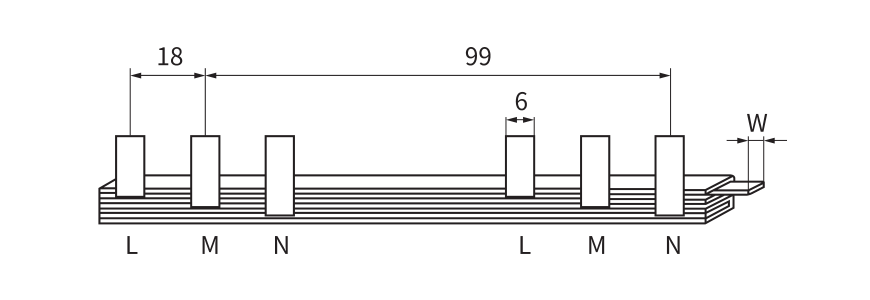
BV2 Peigne de raccordement en cuivre pour disjoncteur

BV2 Peigne de raccordement en cuivre pour disjoncteur

Configuration
Voir le dessin
Cuivre
10 mm²
Courant nominal
63 A
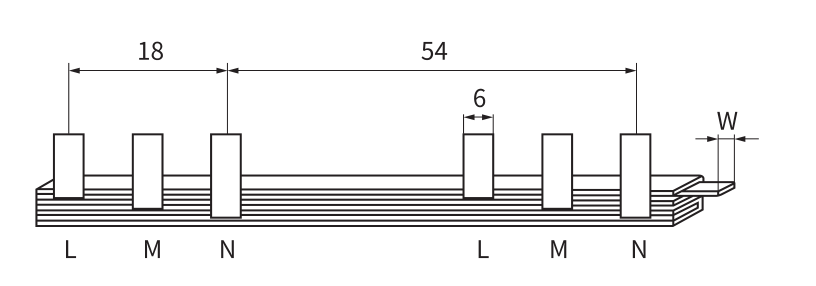
DZ108 Peigne de raccordement en cuivre pour disjoncteur

DZ108 Peigne de raccordement en cuivre pour disjoncteur

Configuration
Voir le dessin
Cuivre
10 mm²
Courant nominal
63 A
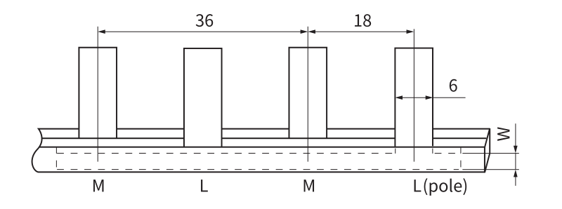
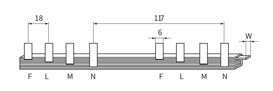
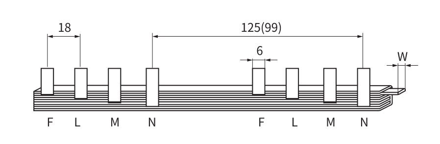
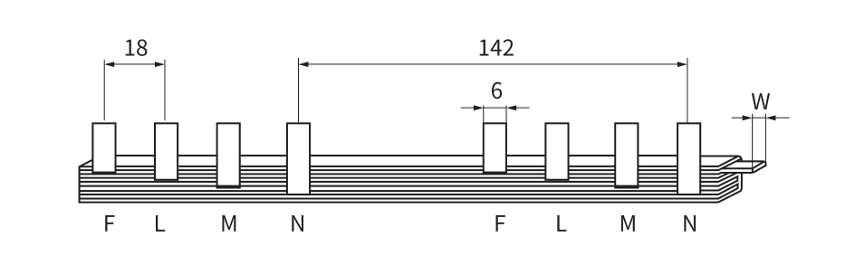
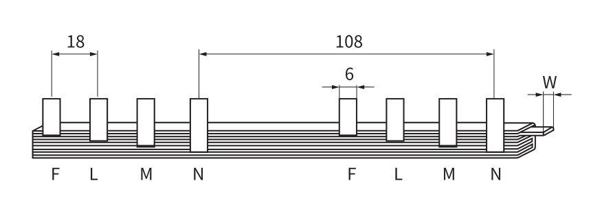
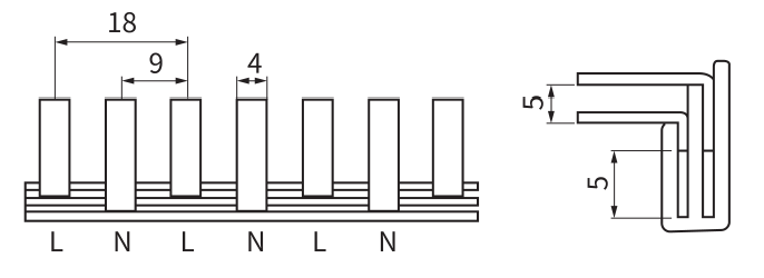
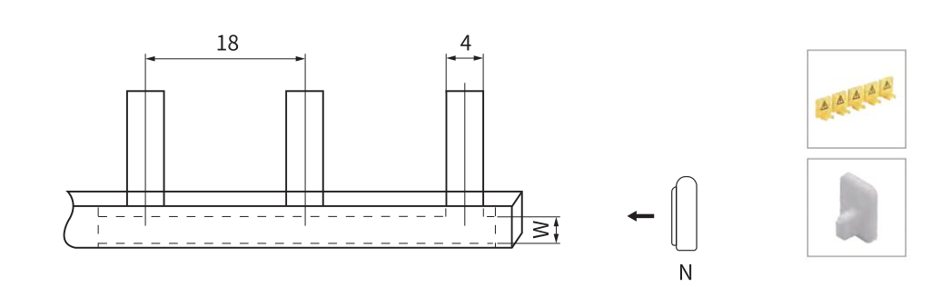
BS101 · Peigne de raccordement à broches 1P
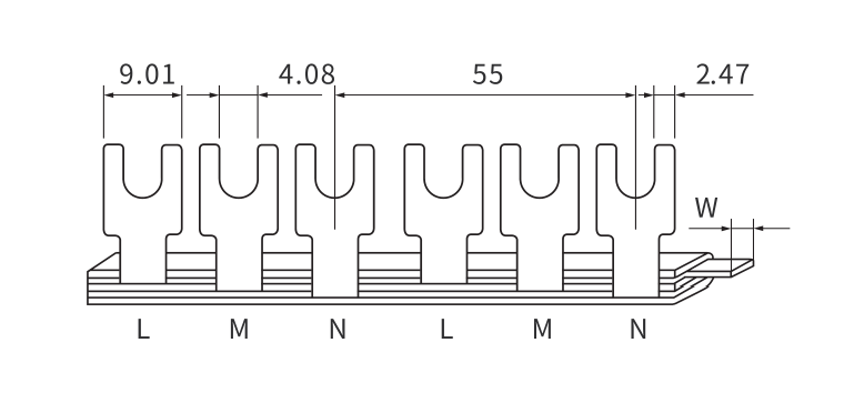
Ouvrir le dessin coté ↗

GÉOMÉTRIE DE CONNEXION

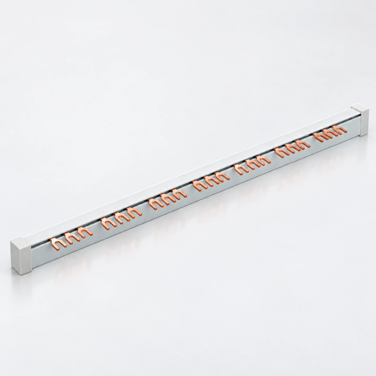
Barres omnibus à broches

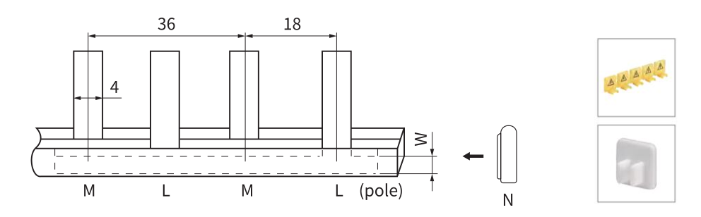
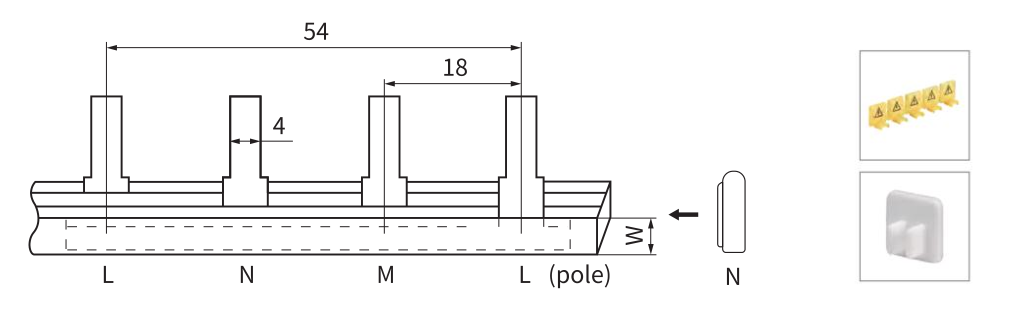
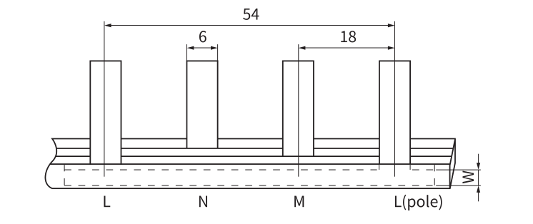
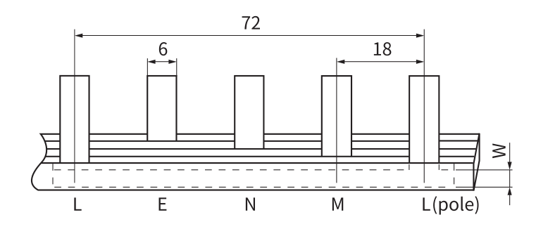
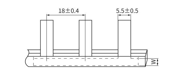
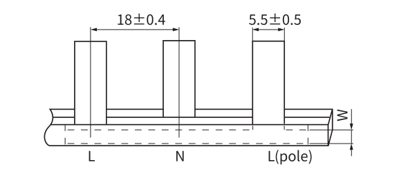
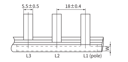
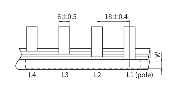
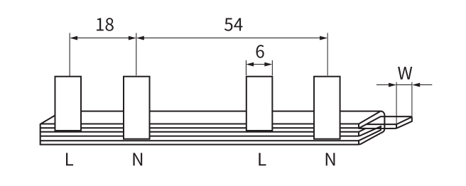
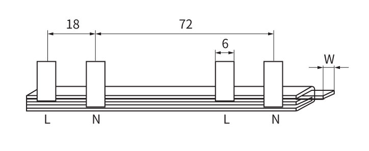
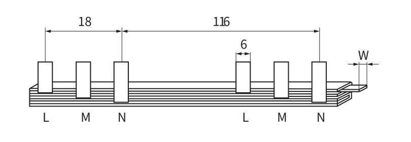
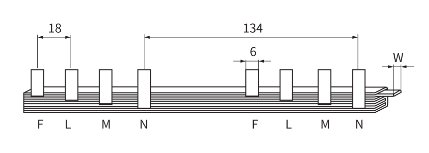
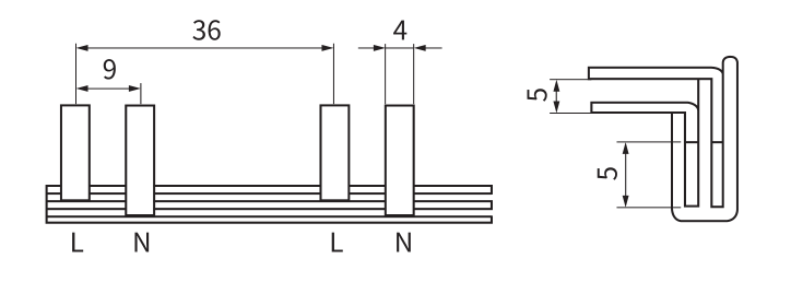
Une barre omnibus à broches utilise des contacts saillants pour connecter une rangée répétée de bornes d'appareils compatibles. YOCL BS101, BS102, BS103 et BS104 couvrent respectivement les configurations 1P, 2P, 3P et 4P.

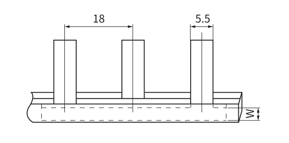
Choisissez d'abord la disposition des pôles, puis comparez l'épaisseur, la largeur et le pas des dents de la broche avec la borne réceptrice. Une valeur de courant correspondante seule n'établit pas un ajustement mécanique.

  • Faites correspondre le contact : confirmez l'ouverture de la borne et les dimensions de contact autorisées.
  • Faites correspondre la disposition : check tooth spacing, number of connections and circuit sequence.
  • Match the exact model: use copper size and catalog current from the same model row.

For example, BS101-2 lists 10 mm² copper and 63 A catalog current capacity; BS101-4 lists 16 mm² and 80 A. These are model-specific values, not a rating for every pin busbar.

Compare pin models in the range ↑

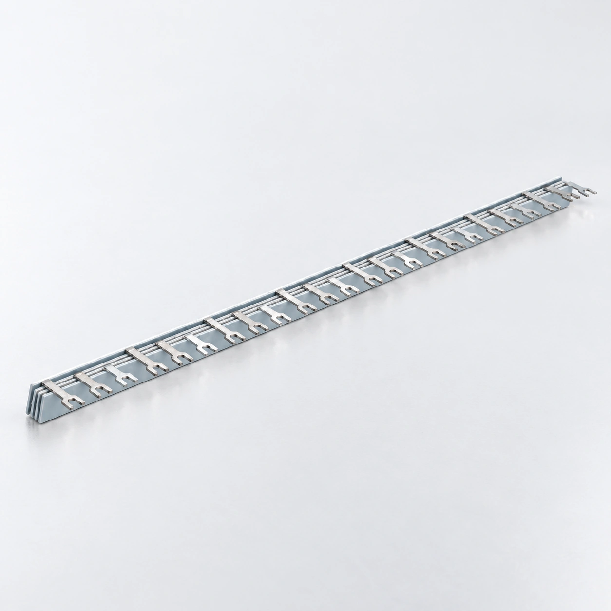
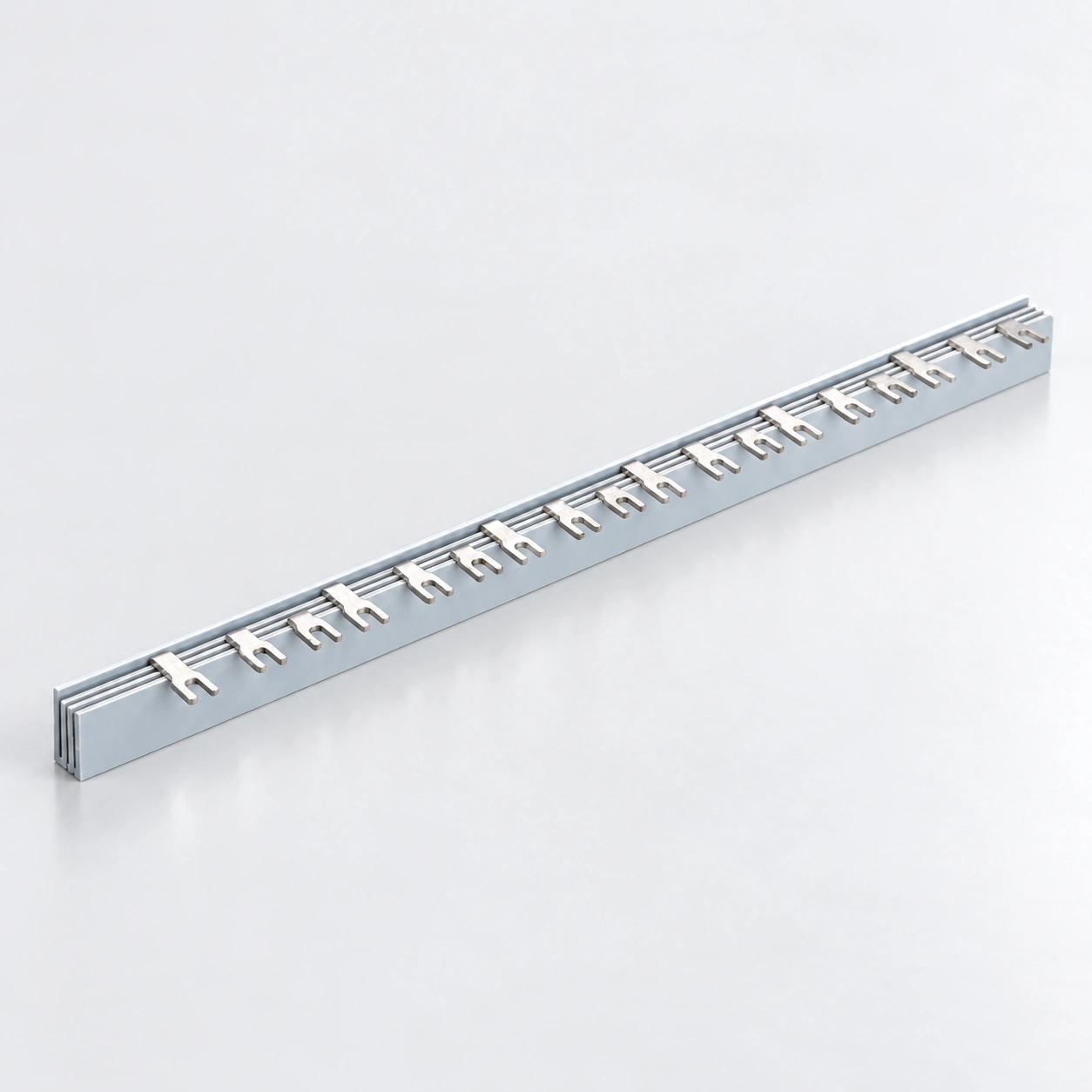
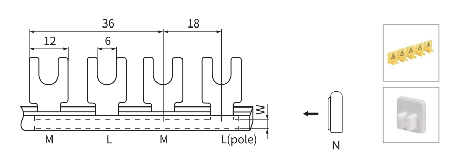
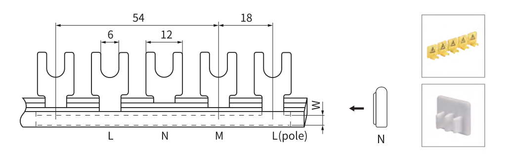
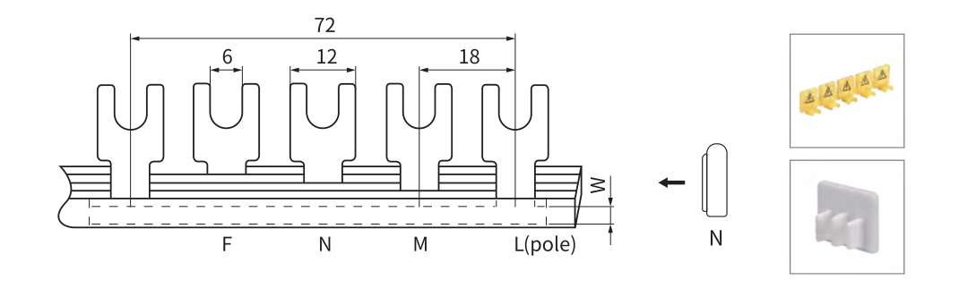
U / Fork Type Comb Busbars

Two related browsing options. Confirm the precise contact geometry before choosing a replacement.

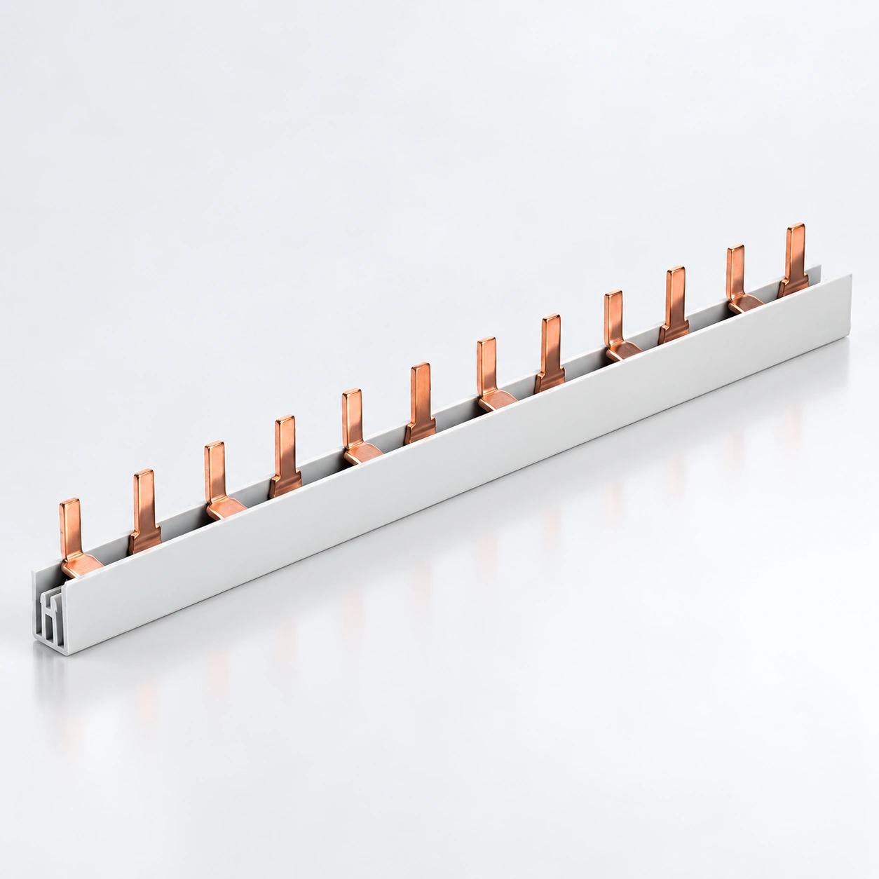
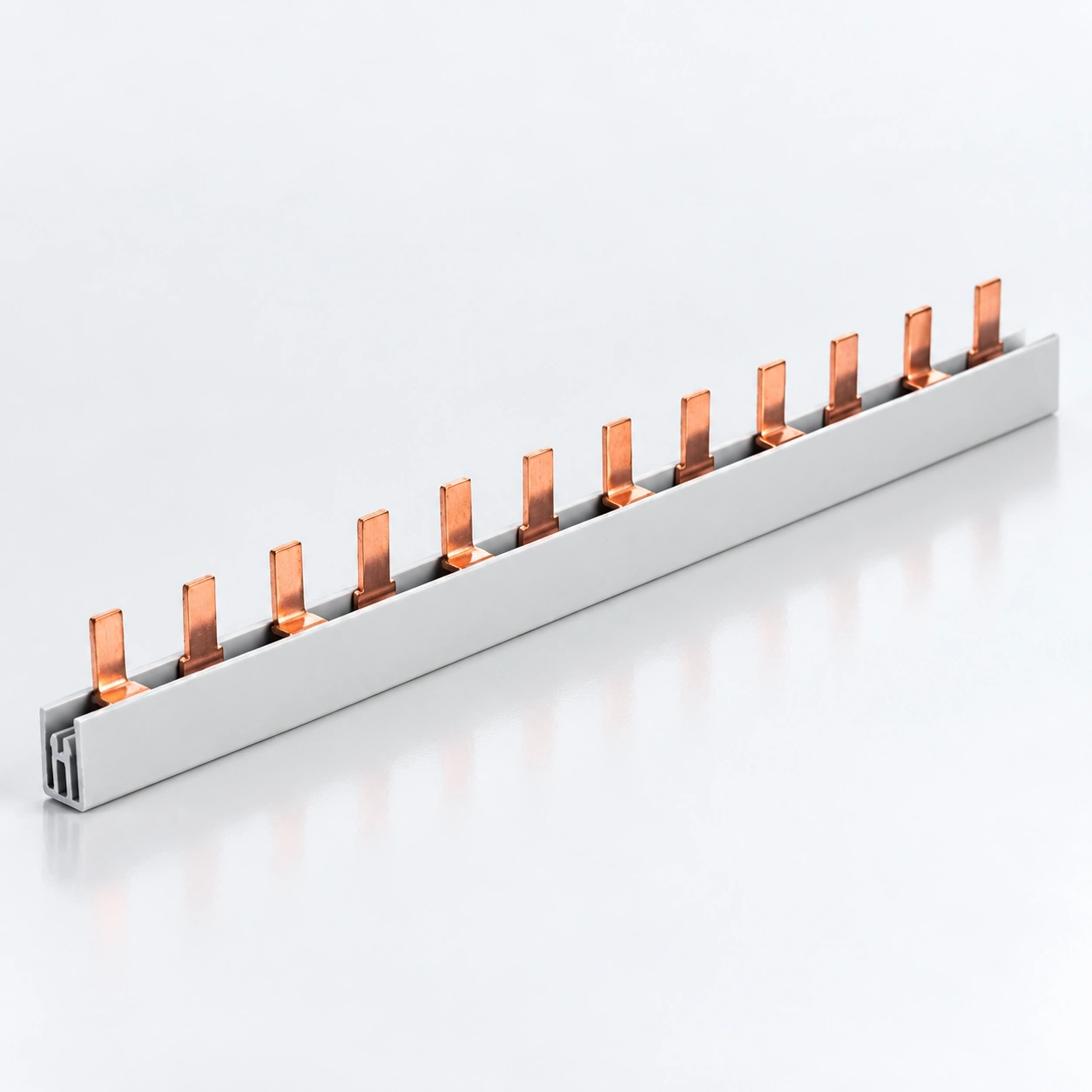
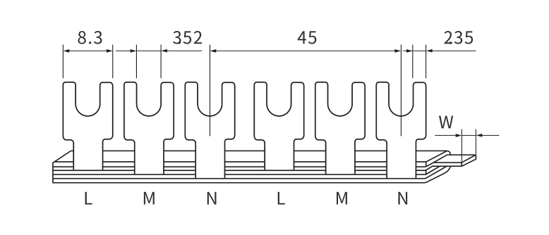
BS201 · 1P C45 fork type
Ouvrir le dessin coté ↗
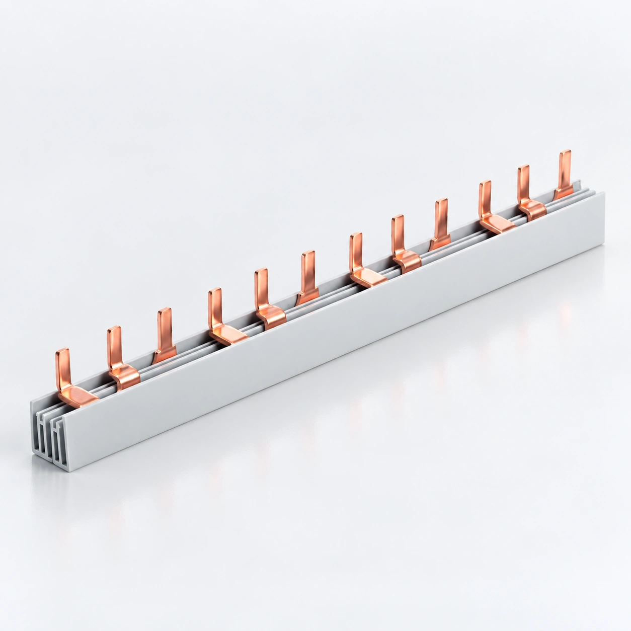
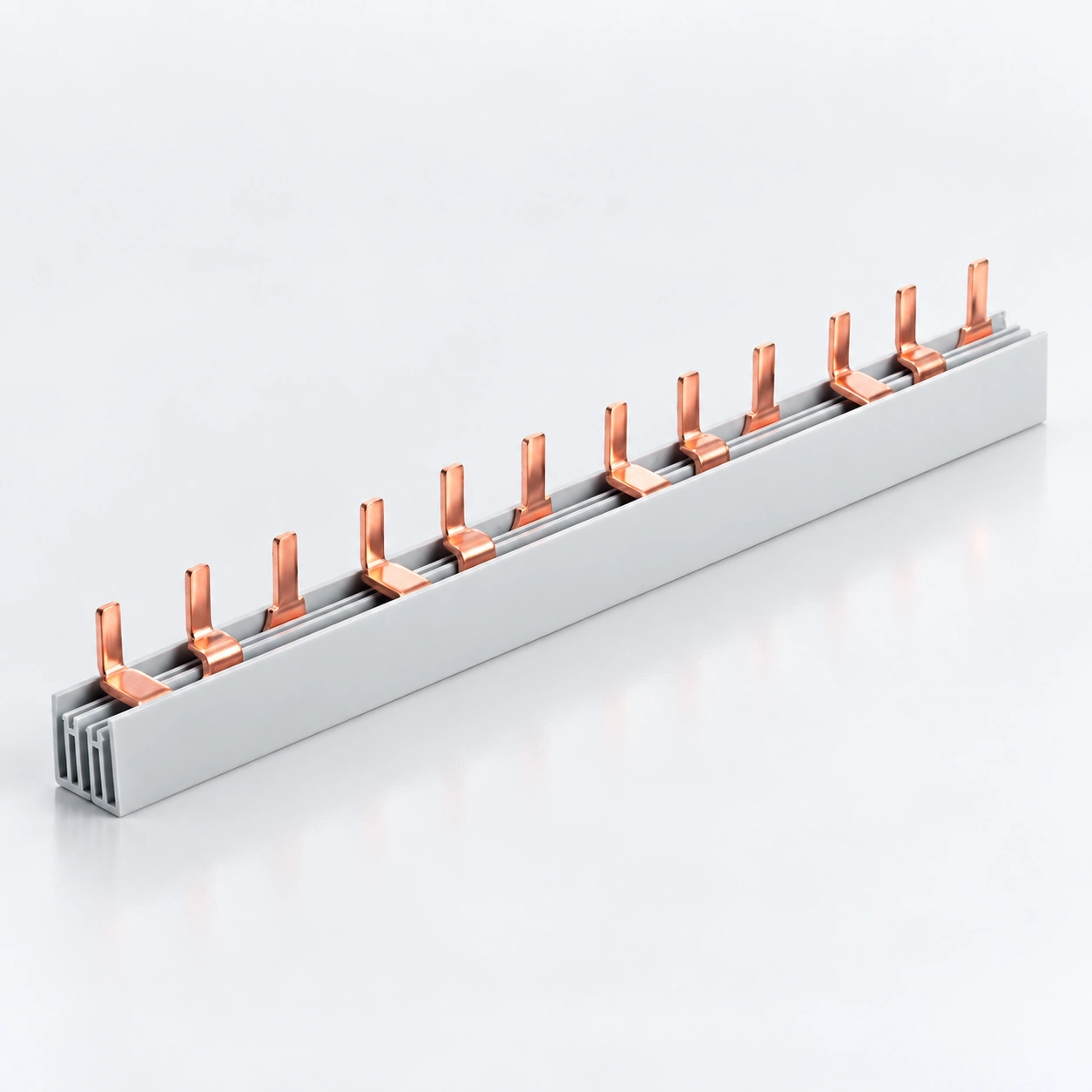
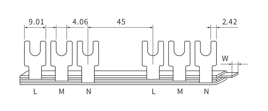
BS301 · 1P U-type
BS301 · 1P U-type
Ouvrir le dessin coté ↗

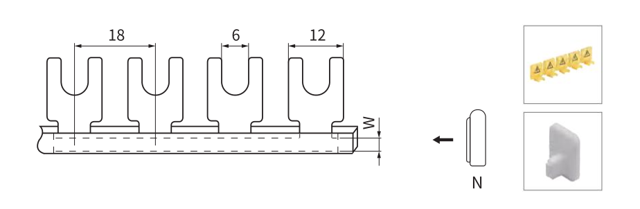
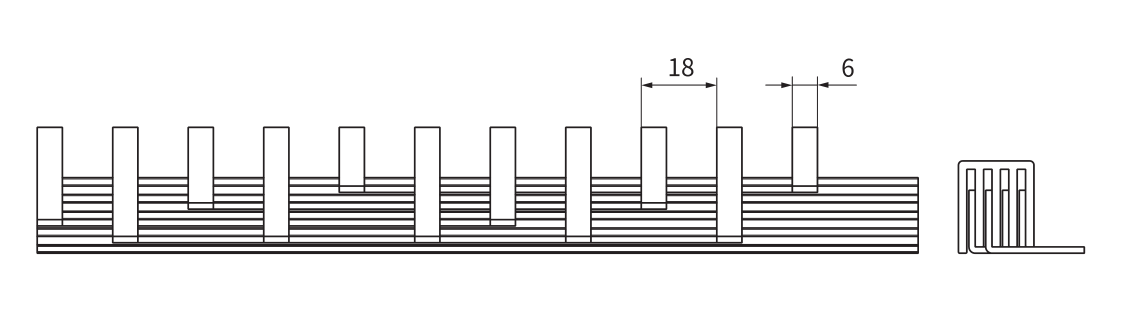
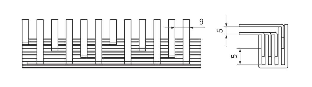
The BS201–BS204 C45 fork range and BS301–BS304 U-type range each include 1P–4P series. They are grouped together for browsing, but their model designations and drawings remain separate.

Compare the contact opening, contact thickness, engagement dimensions and spacing with the device terminal. Do not substitute a fork or U-type busbar for a pin type solely because the number of poles is the same.

  • C45 fork: select BS201, BS202, BS203 or BS204 for the required pole arrangement, then check the model dimensions.
  • U-type: review BS301, BS302, BS303 or BS304 separately against the receiving terminal.
  • Replacement orders: send the installed busbar drawing or clear contact-end photographs together with the device model.
Compare U / fork models in the range ↑

Comb busbar series specifications

Published product data, summarized by series. Open the product table for paired model values and dimensions.

Series / productConnection / configurationPôlesCopper sizesCourant nominalModel optionsDrawing
Barres omnibus à broches MCB série BS101 1Ppin1P6–16 mm²40–80 A4View drawing ↗
Barres omnibus à broches MCB série BS102 2Ppin2P6–16 mm²40–80 A4View drawing ↗
Barres omnibus à broches MCB série BS103 3Ppin3P6–16 mm²40–80 A4View drawing ↗
Barres omnibus à broches MCB série BS104 4Ppin4P6–16 mm²40–80 A4View drawing ↗
Barres omnibus à fourche MCB série BS201 1P C45fourche (C45)1P6–16 mm²40–80 A4View drawing ↗
Barres omnibus à fourche MCB série BS202 2P C45fourche (C45)2P6–16 mm²40–80 A4View drawing ↗
Série BS203 3P Barres omnibus à fourche pour disjoncteurs miniatures C45fourche (C45)3P6–16 mm²40–80 A4View drawing ↗
Barres omnibus pour disjoncteurs BS204 Série 4P C45 Fourche MCBfourche (C45)4P6–16 mm²40–80 A4View drawing ↗
Barres omnibus MCB type U série BS301 1PType U1P6–16 mm²40–80 A4View drawing ↗
BS302 Série 2P Barres omnibus pour disjoncteurs modulaires de type UType U2P6–16 mm²40–80 A4View drawing ↗
Barres omnibus MCB type U série BS303 3PType U3P6–16 mm²40–80 A4View drawing ↗
Barres omnibus pour disjoncteurs miniatures type U série BS304 4PType U4P6–16 mm²40–80 A4View drawing ↗
Barres omnibus pour disjoncteurs BS201D Série 1P C45 MCBC451P6–16 mm²32–100 A5View drawing ↗
Barres omnibus pour disjoncteurs BS202D Série 2P C45 MCBC452P6–16 mm²32–100 A5View drawing ↗
Barres omnibus pour disjoncteurs BS203D Série 3P C45 MCBC453P6–18 mm²32–100 A6View drawing ↗
Barres omnibus pour disjoncteurs miniatures série BS204D 4P C45C454P6–16 mm²40–80 A4View drawing ↗
BS2P-1 2P Barre omnibus triphasée en cuivre2P TriphaséSee configuration10 mm²63 A1View drawing ↗
BS3P-1P+N en Cuivre pour Disjoncteur DPN 3DPN 3P+NSee configuration10 mm²63 A1View drawing ↗
BS401 C451P-L en Cuivre pour DisjoncteurC451P-LSee configuration6–13 mm²32–63 A5View drawing ↗
BS402 C452P-L Barres omnibus MCB en cuivreC452P-LSee configuration6–13 mm²32–70 A5View drawing ↗
BS403 C453P-L Barres omnibus MCB en cuivreC453P-LSee configuration6–13 mm²40–70 A3View drawing ↗
BS404 3P 2 Barres omnibus MCB en cuivre3P 2See configuration10–13 mm²63–150 A3View drawing ↗
BS404 C454P-L Barres omnibus MCB en cuivreC454P-LSee configuration10–13 mm²63–70 A2View drawing ↗
BS404-1 3 PNC DZ158 Barres omnibus MCB en cuivre3 PNC DZ158See configuration13 mm²100 A1View drawing ↗
BS404-1 4Peigne de raccordement en cuivre pour disjoncteur modulaire PLE4PLESee configuration10 mm²63 A1View drawing ↗
BS404-1 DZ158 NC100 4Peigne de raccordement en cuivre pour disjoncteur modulaire PNCDZ158 NC100 4PNCSee configuration13 mm²100 A1View drawing ↗
BS501LE C651P-LE Barres omnibus MCB en cuivreC651P-LESee configuration6–13 mm²40–70 A3View drawing ↗
BS502 C652P-LE Barres omnibus en cuivre pour disjoncteurs miniaturesC652P-LESee configuration10–13 mm²63–70 A2View drawing ↗
BS503 C653P-LE Barres omnibus MCB en cuivreC653P-LESee configuration6–13 mm²40–70 A3View drawing ↗
BS504 C654P-LE Barres omnibus en cuivre pour disjoncteurs miniaturesC654P-LESee configuration6–13 mm²40–70 A3View drawing ↗
BS601 Peignes de raccordement en cuivre pour disjoncteur modulaire DPNDPNSee configuration6–13 mm²32–70 A5View drawing ↗
BS602 Barres omnibus DPNLE en cuivre MCBDPNLESee configuration6–13 mm²32–70 A5View drawing ↗
BS808 AC CJX2 Barrette omnibus en cuivreAC CJX2See configuration13 mm²63 A1View drawing ↗
BV2 Peigne de raccordement en cuivre pour disjoncteurSee product drawingSee configuration10 mm²63 A1View drawing ↗
DZ108 Peigne de raccordement en cuivre pour disjoncteurSee product drawingSee configuration10 mm²63 A1View drawing ↗

Ranges summarize different models; they do not mean that every copper size has every listed current capacity. The source tables identify nominal and maximum operating voltage separately. Check the exact model, supply arrangement and installation conditions before approval.

Check the connection before you order.

Use a device reference and a dimensioned drawing to make compatibility review practical.

Tooth pitch & device width

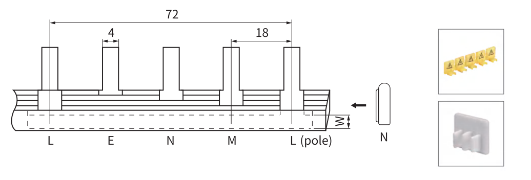
Tooth pitch is the distance between corresponding points on adjacent contacts. Compare it with the actual device-terminal spacing, including any gaps for auxiliary devices. A pole designation does not specify pitch or overall length.

Poles, teeth & modules

Poles describe the electrical arrangement; teeth describe physical connection points. Module count and connected-device count depend on the layout. Supply a circuit schedule rather than assuming that “3P” means three teeth.

Supply & loading

State the incoming feed location, total load and operating conditions. Use the selected manufacturer's assembly instructions; a catalog current value is not a substitute for reviewing the completed distribution assembly.

Insulation & end protection

Confirm insulation dimensions, exposed contacts and the required end caps or tooth covers. Ask whether accessories are included. Cutting permission and finishing requirements must be confirmed for the selected model.

DPN, DPNLE, C45-L, C65-LE, DZ158/NC100 and AC CJX2 are equipment-specific configurations in this range. Their names do not establish compatibility with every device using a similar designation.

Turn your drawing into an order specification.

Agree the design and acceptance criteria before approving supply.

Dimensional review

Provide contact shape, copper cross-section, thickness, pitch, overall length, pole sequence and device-terminal details. The linked model drawings provide a starting point for comparison.

Sample confirmation

Request a sample of the exact proposed model and agree the fit checks needed for your equipment. Confirm any deviations from the published drawing before placing the production order.

Inspection requirements

Specify the dimensions and tolerances to be checked, conductor-material documentation, surface and insulation requirements, and any required electrical test evidence. Agree availability and acceptance criteria with the quotation.

Custom supply review

Send requested lengths, connection layouts, identification, pack quantities and shipment requirements. Custom tooling, samples, minimum quantities and lead times require a feasibility review; they are not assumed available for every model.

Need separate neutral-wire termination? Explore brass neutral bars. For the wider assembly, review power distribution blocks et electrical enclosures.

Match the busbar to the device—not just the current.

Select the interface first, then check the electrical and dimensional requirements for the complete assembly.

Connection shape & pitch

Compare pin, fork and U-type profiles. Provide the device model, terminal drawing and tooth spacing; similar appearance does not establish compatibility.

Poles & circuit layout

Specify 1P, 2P, 3P, 4P or the exact phase-and-neutral arrangement. Check the terminal sequence, module count and any auxiliary-device spacing.

Copper size & current

Use the copper cross-section, thickness, width and catalog current capacity from the same model row. Confirm the feed arrangement and operating conditions.

Length & insulation

Specify the required length, number of connections and end protection. Confirm whether cutting is permitted for the selected product and which accessories are required.

Send your comb busbar
exigences.

Send the busbar model, device reference, pole arrangement, connection drawing and quantities. Include any required length, insulation and packing details.

Préparer une demande

A busbar specification ready for review.

Validez la spécification et les preuves requises avant de passer votre commande.

Explorer la fabrication

Modèles et quantités

List complete BS model codes and quantities. Identify the connection type and pole arrangement for each item.

Device compatibility

Provide the receiving device model and terminal dimensions, tooth pitch and installation layout. Confirm the fit before approving a production order.

Electrical duty & documentation

State operating current, voltage, ambient conditions and feed location. Request model-specific installation information and applicable test documentation.

Dimensions & packing

Send length and dimensional requirements, end protection, labels and quantities per pack. Custom options are subject to drawing and feasibility review.

Comb Busbar for model and packing review

OEM et EMBALLAGE

Votre spécification.
Votre plan d'emballage.

Build your comb busbar order around the selected models, identification and supply requirements.

Planning des modèles

List complete BS model codes and quantities. Identify the connection type and pole arrangement for each item.

Étiquettes et identification

Fournir les numéros de pièce, les illustrations d'étiquettes et toute information de lot ou de traçabilité requise pour la commande.

Quantités par pack

Spécifier les quantités par modèle, par emballage individuel, par carton extérieur et la destination de livraison.

Explorer OEM et ODM

Barrette d'alimentation
questions d'achat.

What information is needed to match a comb busbar to my MCB?

Send the device brand and exact model, a terminal drawing or clear photographs, pole arrangement, tooth pitch, contact dimensions, required connection count and operating requirements. Mechanical fit and electrical suitability must both be reviewed.

Does a 3P busbar have only three teeth?

Not necessarily. 3P identifies the pole arrangement, while the number of teeth and connected devices depends on the product layout and length. Confirm both the pole arrangement and the required connection count.

Are end caps and unused-tooth covers included?

Confirm the accessory list for the selected model with your quotation. Do not assume that a displayed busbar includes every end cap, feed connector or protective cover required for the completed installation.

Can I request a different length or contact layout?

Provide a dimensioned drawing, device interface, quantities and any insulation or marking requirements. Feasibility, tooling, samples and commercial terms are reviewed for the requested design.

Where can I find the dimensional drawings?

The series comparison table links directly to published dimension drawings. Open the corresponding product page for the model table, and request clarification if pitch, length or another required dimension is not specified.

What is the difference between a comb busbar and an MCB busbar?

Comb busbar describes the repeated connection-tooth structure; MCB busbar describes its use with miniature circuit breakers. This range also includes equipment-specific copper connection bars, which must be selected by their own drawings.

Are pin and fork busbars interchangeable?

Do not assume they are. The connection profile must match the receiving terminal, including tooth dimensions, engagement and spacing.

Will these fit every brand of MCB?

No universal compatibility is claimed. Provide the exact device model and terminal drawing for a compatibility review.

Can every comb busbar be cut to length?

No blanket cutting approval applies. Confirm the selected model's instructions, permitted cutting method and required insulation and end protection before modifying it.

Does the same copper cross-section always mean the same current capacity?

No. Use the complete model row and its catalog current value; also confirm the installation and feed conditions. Do not transfer a rating between different series based only on copper size.

How are comb busbars different from neutral bars?

Comb busbars connect to a repeated equipment-terminal layout. Neutral bars provide multiple neutral-wire termination points. Select each for its intended connection and installation arrangement.

Que dois-je inclure dans une demande de devis ?

Send the busbar model, device reference, pole arrangement, connection drawing and quantities. Include any required length, insulation and packing details. Include the exact model quantities, delivery destination and required documentation.

Pouvez-vous examiner les étiquettes et les emballages personnalisés ?

Envoyez vos numéros de pièce, les illustrations des étiquettes, les quantités par emballage et les exigences d'expédition. La faisabilité, les exigences d'échantillons, les quantités minimales et les délais de livraison sont confirmés pour les modèles demandés.

Détails du projet

Les champs marqués d'un * sont obligatoires.
Vos coordonnées seront utilisées pour répondre à votre demande. Notice de confidentialité