
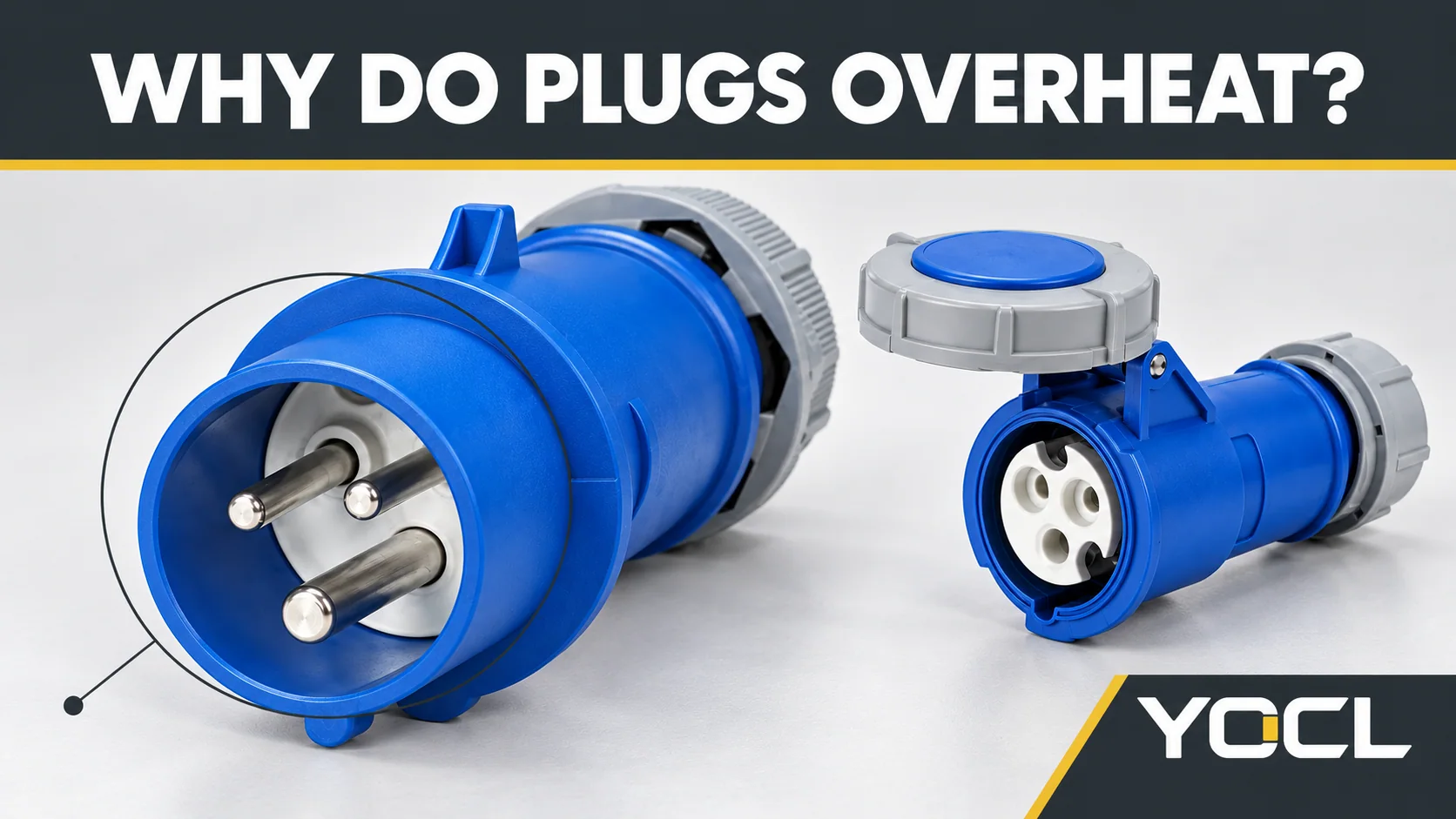
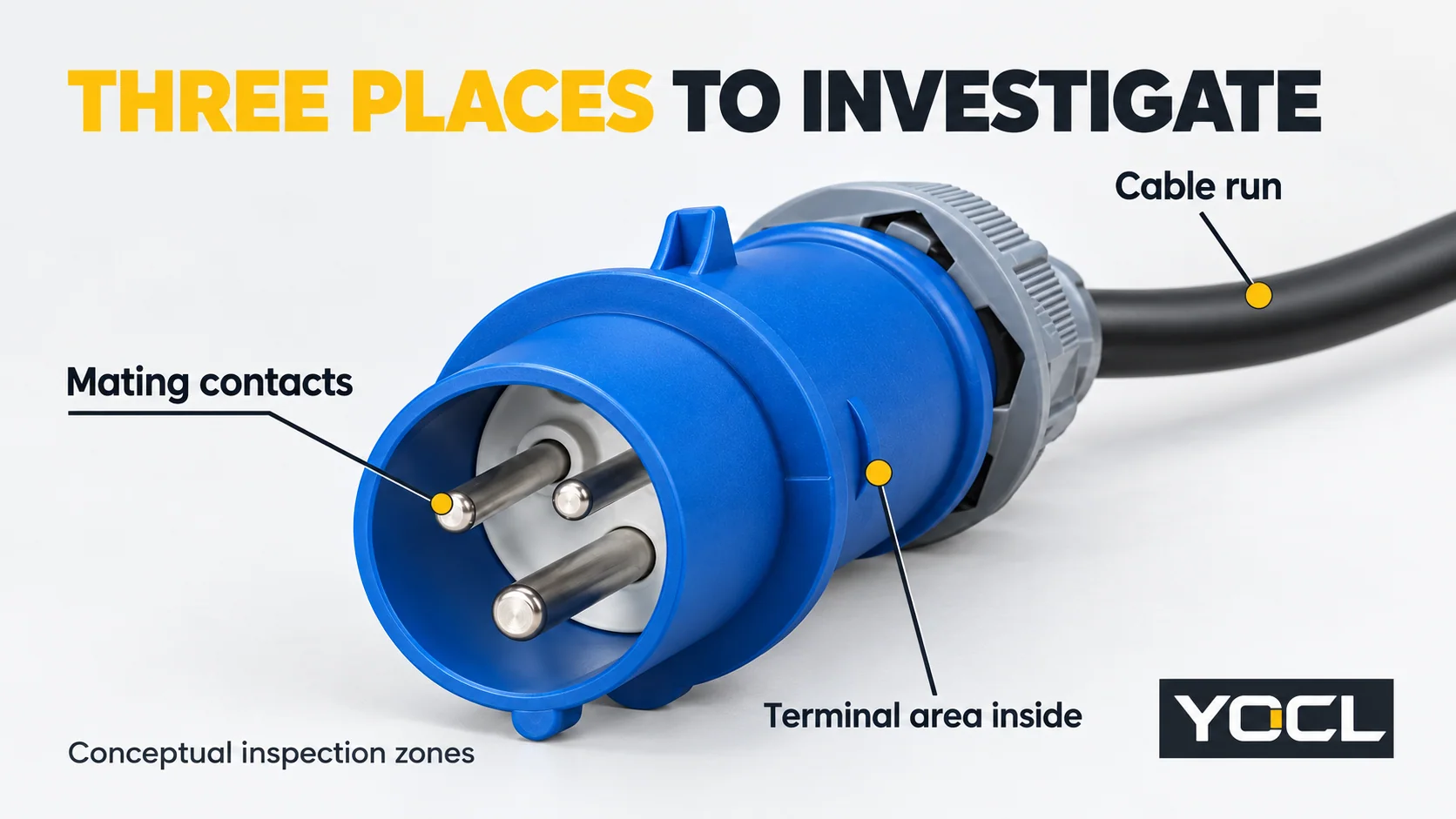
Les prises et fiches industrielles surchauffent lorsqu'une chaleur excessive se développe au niveau d'un contact d'accouplement ou d'une terminaison de fil, lorsque le câble ou la connexion n'est pas adapté à la charge et aux conditions d'installation, ou lorsque la chaleur ambiante ne peut pas s'échapper. La première distinction utile est la zone de contact d'accouplement, la terminaison arrière ou le cheminement de câble. Chacun indique des preuves et des travaux correctifs différents.
Une odeur de brûlé, de la fumée, des arcs électriques, des pièces fondues ou déformées, une isolation endommagée et des signes de brûlure imposent l'arrêt de l'utilisation et la mise en sécurité de l'équipement. Ne débranchez pas un connecteur suspect lorsqu'il est sous charge et ne le touchez pas pour évaluer sa température. Le guide de sécurité des équipements du Health and Safety Executive britannique identifie les marques de brûlure et les dommages comme des points d'inspection et préconise une évaluation par une personne compétente en cas de doute sur la sécurité.
Points clés
- A hot mating face needs both the plug and socket investigated; replacing only the visibly affected half may leave the cause unresolved.
- A hot rear body needs termination and cable-restraint checks using the exact product instructions. “Tighten it more” is not a diagnosis.
- Heating along the cable needs a load-and-installation review. A larger plug alone does not correct an unsuitable cable or circuit.
For the separate job of identifying poles, keying and rating fields, use Fiches et prises industrielles expliquées. The checks below assume the actual plug and mating socket can be identified.
Make the Assembly Safe Before Physical Checks
Use the site’s safe-isolation procedure and competent personnel before opening a body, examining contacts or correcting a termination. Identify every relevant supply, secure isolation and establish that the parts to be worked on are dead. An equipment stop button, an open lid or a withdrawn plug elsewhere is not enough to assume the whole assembly is safe. These principles are set out in the HSE’s Electricity at work: Safe working practices, third edition, paragraphs 47–55.
Preserve the incident information before parts are cleaned, moved or discarded. Record which half showed the symptom, where it appeared, the connected load, operating duration, recent repairs and any existing temperature images. Do not recreate a dangerous operating condition just to collect a better photograph.
The location of a warm exterior suggests where to investigate; it does not prove which internal connection failed. Heat can spread through the assembly.
Follow the Heat Location to the Next Check
The physical inspections in this table take place only after the assembly has been made safe. Any necessary operating measurements require a separately planned assessment by qualified personnel.
| Symptom or existing evidence | Possible cause | Vérification sûre | What the result means and what to do |
|---|---|---|---|
| Local damage or heating evidence near the mating face | Incomplete engagement, damaged or contaminated contacts, or an unsuitable mating pair | Inspect both halves and their identification; check engagement and retention against the product instructions | A damaged or uncertain interface remains out of service. Confirm the pair and replace affected parts through an approved service route. |
| Heating evidence concentrated toward the rear body | Incorrect conductor preparation, an unsuitable terminal combination, a loose or damaged termination, or cable movement | A competent person examines the actual terminal and cable restraint using the exact instructions | Correct a verified assembly error only if the parts remain serviceable. Heat-damaged or stripped components need replacement. |
| Heating extends along the cable or affects several connected parts | Load/duty mismatch, cable installation constraints, external heat, or more than one fault | Review load records, cable identity, route, ambient conditions and every component in the connection | Reassess the assembly and circuit together. Do not assume the plug is the limiting item or simply increase its rating. |
| One comparable contact path appears warmer than others | A local connection defect or unequal current | Compare the existing thermal evidence with actual current and duty for each path | Similar appearance does not establish similar loading. Investigate the outlier without treating it as proof of a loose terminal. |
| Overheating returns after a repair or when the cable moves | Unresolved mating damage, termination error, cable restraint or unsuitable duty | Review both halves, the previous repair and the permitted cable movement | Escalate the recurring fault. Repeated tightening or repeated replacement of one half is not an adequate corrective plan. |
If the Mating Face Is Affected, Check Both Halves
The contact interface belongs to the plug and socket together. Identify the exact pair before deciding that a worn-looking plug is the only defective component.
Look for damage, deposits, corrosion, displaced contacts, abnormal fit, and evidence that the connection did not fully engage. Check the intended retention arrangement rather than using cable tension to hold the pair together. Matching housing colour or an apparently correct fit cannot establish a documented mating combination; the clock-position and colour-code guide explains the identification fields without replacing exact-pair confirmation.
The electrical mechanism is resistive heating: P = I²R. At the same current, a higher local resistance generates more heat. EPRI’s Electrical Connector Application Guidelines, sections 4.4.2–4.4.3 and Appendix B, discusses contact degradation and the effect of increased connection resistance. This supports the mechanism; it does not establish a failure rate or test result for a YOCL model.
That distinction explains why a circuit can have a local overheating problem without the operating current obviously exceeding the connector’s label. A protective device that has not tripped is not evidence of a healthy contact interface.
Do not bend pins or socket contacts to recover grip, file a damaged contact, or apply an unapproved cleaner or lubricant. If a contact or its surrounding insulation is damaged, keep the connection out of service and use the manufacturer’s permitted repair or replacement route. Review the mating half as well; a new component should not be connected to an unresolved damaged interface.
If the Rear Body Is Affected, Investigate the Termination
A termination check needs more information than the nominal cable size. Obtain the connector instructions for the exact model and verify:
- The accepted conductor material, cross-section and construction.
- The required conductor preparation and whether the prepared end is permitted.
- The specified insertion or clamping method and any applicable tightening torque.
- The cable-entry range and how the jacket is restrained against movement.
These are verification fields, not universal installation values. A ferrule or other prepared end must be accepted by that terminal; its use elsewhere does not prove suitability here.
The examiner should determine whether the intended conductor is actually secured, whether strands or insulation were damaged during preparation, and whether cable pull or twisting reaches the terminals. A correctly sized jacket entry does not by itself prove a correct electrical termination.
If the cause is a verified preparation error and all affected parts remain serviceable, correction follows the exact instructions. If there are damaged threads, deformed clamping parts, burned conductors or degraded insulation, tightening does not restore the original component condition. Replace or repair through the permitted service procedure, with the extent of cable damage assessed as well.
If torque or conductor-preparation information is missing, obtain it before correcting the connection. Do not borrow a torque value from another current rating or infer it from the screw size.
If the Cable Run Is Affected, Review Load and Installation Together
Establish the actual current and operating duration, not just the machine’s nominal power. Include changes in connected equipment, duty and simultaneous loads through any distribution or adapter arrangement. Review the plug, socket, cable and circuit protection as one installation.
Cable routing matters to the investigation: identify enclosed or bundled sections, coiled flexible leads where relevant, nearby heat sources and any conditions that restrict heat removal. Have the installation assessed against the cable’s documented duty and the applicable design requirements. This article supplies no universal cable-current table or automatic derating factor.
Even closely related YOCL products have different declared electrical and conductor fields. For example, the current YOCL IP44 industrial plug model table lists:
| Complete model | Courant déclaré | Listed contact arrangement | Listed voltage / clock | Listed conductor capacity |
|---|---|---|---|---|
| NM-013H | 16 A | 2P+E | 220–240 V / 6h | 1–2.5 mm² |
| NM-023H | 32 A | 2P+E | 220–240 V / 6h | 2.5–6 mm² |
These are first-party catalogue declarations, not approval of a particular installed assembly. 2P+E means two current-carrying poles plus protective earth. The shared voltage, contact arrangement and clock entry do not make the rows interchangeable. The table’s conductor capacity is a terminal cross-sectional range, not the cable-jacket diameter or a complete cable ampacity calculation.
Replacing the 16 A plug with a 32 A product therefore requires a review of the mating socket, cable, terminations, equipment and protection. It is not a standalone overheating remedy. Likewise, changing an ingress-protection category does not resolve a resistive contact fault.
Read Temperature Evidence With Its Load Conditions
“It feels hot” and an isolated thermal-camera value are insufficient acceptance criteria. Do not touch-test a suspect assembly or open it while energized to obtain a better view.
If thermal records already exist, retain the load at the time, operating duration, ambient conditions, viewing position and surface being observed. Comparing two poles or two connectors is useful only when their loading and conditions are sufficiently comparable. A neutral and a phase conductor need not carry the same current.
EPRI’s thermography discussion, Appendix B, explains that surface emissivity and reflected radiation can affect apparent temperature, especially on shiny metal, and that comparisons need similar electrical loading. A casing image also cannot expose a concealed contact directly. Use it to guide a competent investigation rather than declare a universal pass or fail.
No single case temperature, temperature difference or “too hot to hold” rule is used here. Acceptance needs the selected product’s documented limits, the cable and equipment conditions, and the maintenance assessment. A cool reading after shutdown cannot clear a fault observed under load.
Repair, Replace or Hold: The Return-to-Service Decision
Return to service requires a resolved cause and verified corrective work, not simply a cooler housing after a pause.
- Hold the assembly when the mating identity is uncertain, instructions are missing, or the cause remains unexplained. Recurring heat or intermittent contact requires escalation.
- Correct a confirmed assembly error only where the manufacturer permits the work and the contacts, terminals, insulation and cable remain serviceable. Record what was wrong and how it was corrected.
- Replace damaged components through the approved service route. Assess both mating halves and the cable; neither a replacement plug nor a tightened terminal clears damage elsewhere.
- Verify the completed work under the site’s inspection, testing and controlled return-to-service procedure. Include any required connection, protective-earth, insulation and functional checks appropriate to the actual assembly. The required methods and acceptance values must come from the applicable procedure, not this article.
The investigation record should identify the plug and socket models, affected location, cable construction and size, load/duty evidence, damage photographs, product instructions used, corrective parts and final verification. This makes a repeat incident traceable.
For YOCL product identification, provide those details through the industrial plugs and sockets product range, including the exact mating component. The IP44 cable-coupler information can help identify a cable-mounted female half. Request the relevant assembly instructions and service-part options before selecting a replacement.
Références
- UK Health and Safety Executive — Work using electrically powered equipment, equipment condition, burn marks, damage and competent-person guidance.
- UK Health and Safety Executive — Electricity at work: Safe working practices, HSG85, third edition, 2013, pp. 20–22, paragraphs 47–55.
- Electric Power Research Institute — Electrical Connector Application Guidelines, report 1003471, December 2002, sections 4.4.2–4.4.3 and Appendix B. General connector and thermography principles; not a YOCL product test.
- YOCL ELECTRIC — IP44 Fiches industrielles, first-party model table, selection notes and original exterior image; accessed 26 October 2026.
- YOCL ELECTRIC — IP44 Coupleurs de câbles industriels, first-party product-format information and original exterior image; accessed 26 October 2026.