
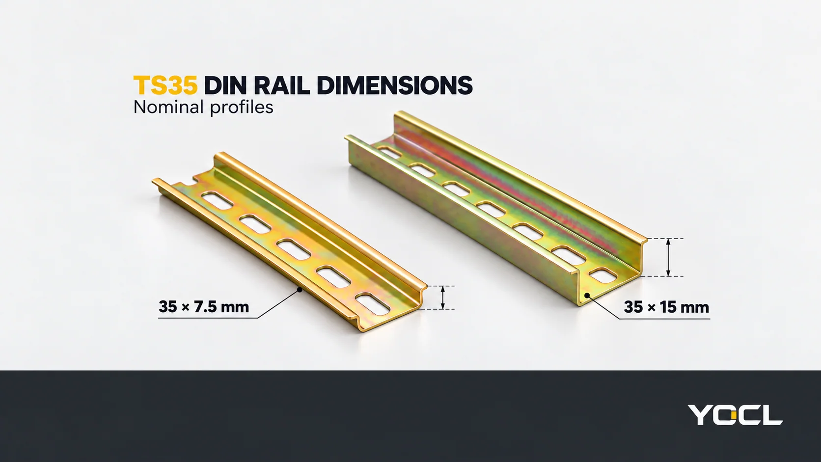
Um TS35 carril DIN tipo chapéu-de-chuva tem uma 35 mm largura de perfil nominal. Os dois tamanhos aqui comparados têm alturas de perfil nominais de 7.5 mm e 15 mm. A altura do perfil, a espessura do material e as dimensões das ranhuras de fixação descrevem características diferentes; uma especificação completa do carril necessita de cada uma delas.
| Tamanho nominal do carril | Largura do perfil | Altura/profundidade do perfil | O que o tamanho identifica |
|---|---|---|---|
| 35 × 7.5 mm | 35 mm | 7.5 mm | A secção TS35 tipo chapéu-de-chuva mais rasa |
| 35 × 15 mm | 35 mm | 15 mm | A secção TS35 tipo chapéu-de-chuva mais profunda |
Estas dimensões nominais são indicadas em YOCL 35 × 7.5 mm carril de aço e 35 × 15 mm carril de aço registos. São uma consulta do tamanho da secção, não um desenho de tolerância ou uma garantia de que um dispositivo específico se adapta a ambas as alturas.
Ler o Tamanho da Secção Separadamente da Espessura
Em 35 × 7.5 mm, o número 7.5 mm descreve a altura do perfil formado. Não significa que o material do carril tenha 7.5 mm de espessura. A mesma distinção aplica-se à altura 15 mm da secção mais profunda.
Por exemplo, a configuração de carril de aço YOCL × 35 com ranhura standard da 7.5 mm oferece 0.9, 1.0 ou 1.2 mm de espessura nominal do material. A sua configuração em aço 35 × 15 mm especifica 1.5 mm espessura nominal. Mantenha estes valores em campos separados ao ler uma cotação ou preparar um desenho.
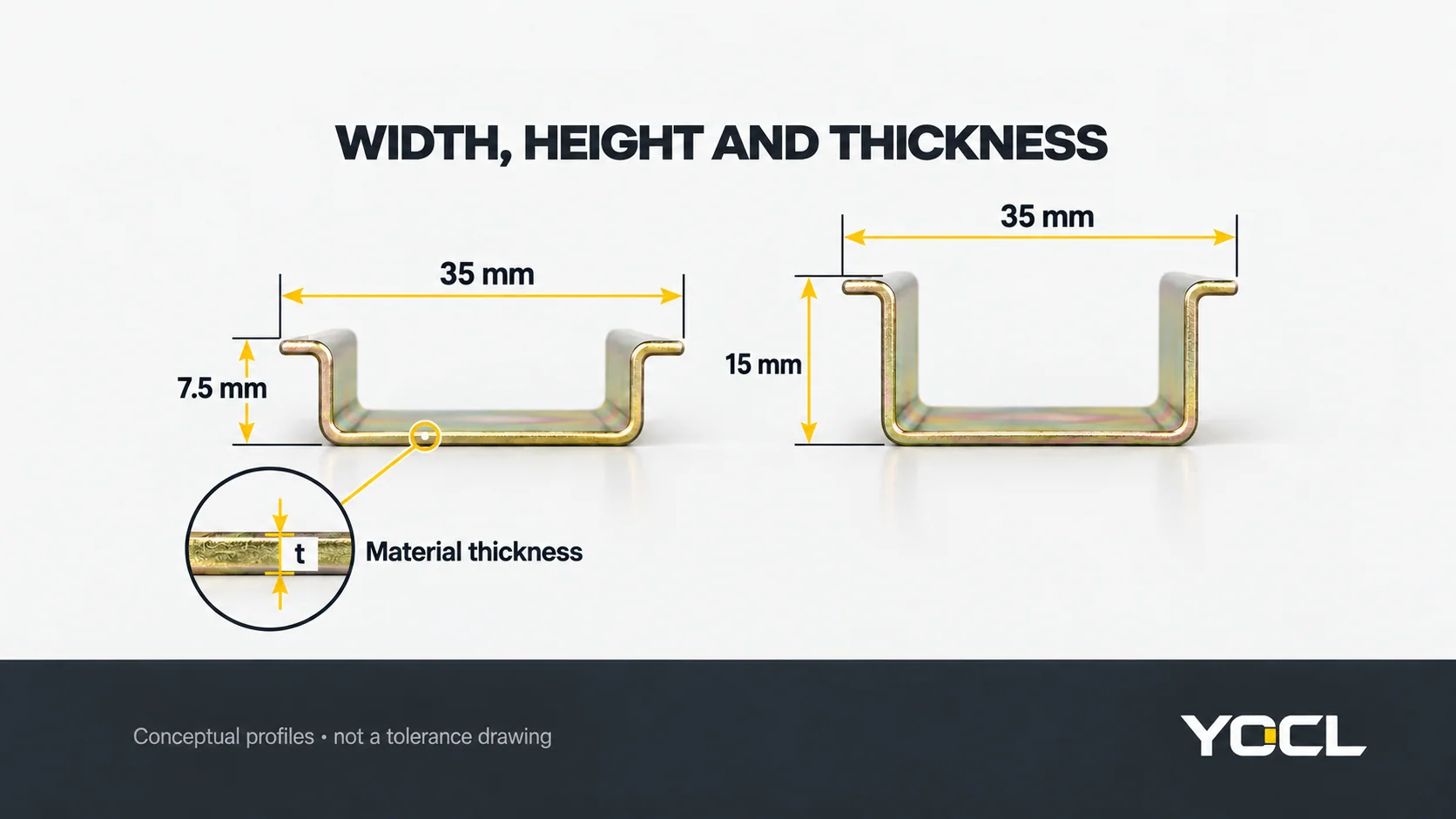
| Campo de dimensão | Descreve | Exemplo da gama YOCL |
|---|---|---|
| Largura × altura do perfil | A secção de carril formada apresentada ao dispositivo | 35 × 7.5 mm ou 35 × 15 mm |
| Espessura nominal do material | Espessura do material do carril selecionado | 1.0 mm aço de ranhura standard; 1.5 mm aço de perfil profundo |
| Largura × comprimento da ranhura | Uma abertura de fixação alongada | 6.2 × 15 mm |
| Passo da ranhura ou disposição dos furos | Posições das aberturas de fixação sucessivas | Obter o desenho da configuração selecionada |
| Comprimento do carril fornecido | Length of the rail before any project-specific cutting | 1 m = 1,000 mm |
A product description containing only “35 mm DIN rail” leaves the height, thickness, openings and length unresolved. It also leaves the detailed flange geometry and dimensional tolerances to the relevant drawing.
YOCL TS35 Thickness, Slot and Length Chart
Use the following chart as a YOCL product-configuration lookup, not as a universal table for every TS35 rail. All profile, thickness and slot values are in millimetres; supplied lengths are in metres.
| Perfil | Material and configuration | Espessura nominal (mm) | Largura × comprimento da ranhura (mm) | Supplied lengths (m) |
|---|---|---|---|---|
| 35 × 7.5 | Steel, standard slots | 0.9 / 1.0 / 1.2 | 6.2 × 15 | 0.5 / 1 / 2 |
| 35 × 7.5 | Steel, long slots | 0.9 / 1.0 / 1.2 | 5.2 × 25 | 0.5 / 1 / 2 |
| 35 × 7.5 | Steel, blue-white appearance | 1.0 | 6.2 × 15 | 1 / 2 |
| 35 × 7.5 | Steel, conventional 1.0 mm section | 1.0 | 6.2 × 15 | 1 / 2 |
| 35 × 7.5 | Steel, ribbed section | 0.8 | 5.2 × 15 | 1 / 2 |
| 35 × 15 | Steel, slotted | 1.5 | 6.2 × 15 | 1 / 2 |
| 35 × 7.5 | Aluminium, smaller slots | 0.7 / 0.9 / 1.1 | 4.2 × 12 | 1 / 2 |
| 35 × 7.5 | Aluminium, longer slots | 1.1 | 4.8 × 25 | 1 / 2 |
Sources: YOCL’s 35 × 7.5 mm slotted steel configuration table, 35 × 15 mm slotted steel specifications e 35 × 7.5 mm slotted aluminium configuration table, checked October 9, 2026. Each slash-separated entry is a listed choice within that row. Keep the selected configuration, thickness, slot size and length together.
Two details are easy to miss:
- A thickness does not uniquely identify the slot pattern. The 1.1 mm aluminium rail is listed with either 4.2 × 12 mm or 4.8 × 25 mm openings.
- Length choices vary by configuration. The steel standard-slot and long-slot rows list 0.5 m lengths; the blue-white, conventional and ribbed rows list 1 m and 2 m.
“Blue-white” identifies the catalogue appearance option. The label does not supply a coating thickness or corrosion classification. The ribbed row likewise supplies dimensions, not an independently verified load rating.
Slot Length Is Not Fixing Pitch
Para uma 6.2 × 15 mm slot, 6.2 mm is the opening width and 15 mm is the opening length. Those values do not state the distance between successive openings.
The deeper steel rail illustrates the distinction particularly clearly: 15 mm profile height e 15 mm slot length appear in the same specification, but they describe different features.
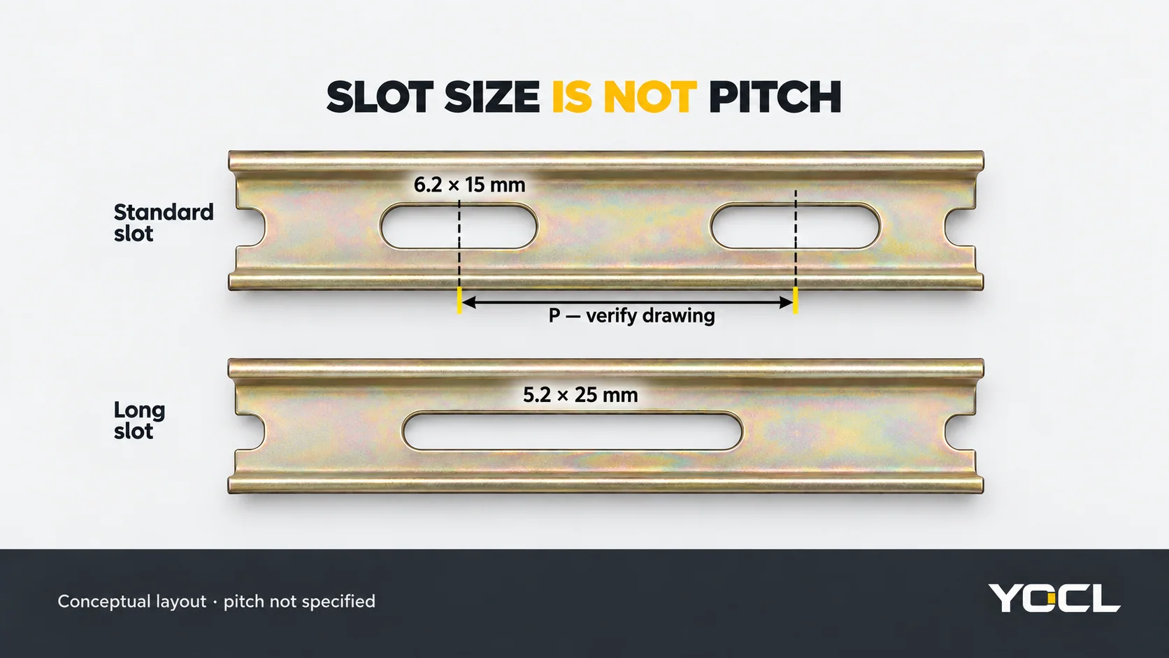
When matching a rail to an existing backplate drawing, obtain the hole-layout information separately. Slot dimensions alone do not establish:
- spacing between openings;
- the position of the first opening relative to a rail end;
- where a project-specific cut falls relative to the slot pattern;
- the specified fastener, head clearance or receiving arrangement.
A longer opening can provide more positioning allowance along the slot, but its width and the rest of the fixing arrangement still need to match. A 5.2 × 25 mm opening should therefore not be treated as an enlarged version of a 6.2 × 15 mm opening in every direction.
Does a Device Accept Both TS35 Heights?
Check the device’s mounting specification rather than deciding from the shared 35 mm width. YOCL’s SJ cage-spring terminal-block record explicitly lists TH35-7.5 ou TH35-15. That declaration applies to the stated SJ range; it does not establish two-height acceptance for every rail-mounted device.
TS35 appears in these rail descriptions, while TH35 appears in the SJ mounting declaration. Match the complete section designation and drawing when checking either label.
For a device documented for both heights, review its installed outline and access requirements against the panel layout. The nominal profile-height difference is 15 − 7.5 = 7.5 mm. That arithmetic does not by itself establish the change in every terminal, release point or device surface: use the actual assembly drawing.
IEC 60715:2017 covers dimensions and functions relevant to compatible mechanical rail mounting. Its public catalogue scope does not supply the full dimensional tolerance drawings. The charts here use YOCL’s nominal product values and do not assert IEC conformity or working-load capacity.
For orientation across top-hat, G-profile and mini rails, use DIN Trilhos Explicados: Perfis, Montagem e Encaixe de Acessórios.
TS35 Dimensions in Inches
Use inches = millimetres ÷ 25.4. The international inch is exactly 25.4 mm, as documented by NIST’s length-unit reference.
| Nominal metric dimension | Calculated inch equivalent, rounded to 3 decimal places |
|---|---|
| 35 mm width | 1.378 in |
| 7.5 mm profile height | 0.295 in |
| 15 mm profile height | 0.591 in |
These are rounded conversions of nominal dimensions, not manufacturing tolerances. Retain the original metric dimensions when identifying the profile and use the specified drawing units for a fit check.
Worked Example: Specify the Aluminium Slot Variant
Suppose a bill of materials requests 35 × 7.5 mm aluminium DIN rail, 1.1 mm thick, 2 m long. That description still matches two rows in the YOCL chart because both slot patterns are listed at 1.1 mm thickness.
If the required opening is 4.2 × 12 mm, a more precise dimensional enquiry is:
TS35 top-hat aluminium DIN rail; 35 × 7.5 mm profile; 1.1 mm nominal thickness; 4.2 × 12 mm fixing slots; 2,000 mm supplied length. Quantity: specify separately. Provide the required fixing layout and the device mounting reference for confirmation.
The values identify one listed configuration. They do not approve its fasteners, support spacing or device fit. Those remaining checks need the project drawing and relevant mounting documentation.
Utilizar o YOCL DIN rail range to route that description to the corresponding product record. Include any drawing revision and dimensional tolerances required by the project instead of assuming that the nominal size chart supplies them.
Referências
- YOCL ELECTRIC — 35 × 7.5 mm Calha em Aço com Ranhuras DIN; first-party nominal section, thickness, slot and length configuration data.
- YOCL ELECTRIC — 35 × 15 mm Calha em Aço com Ranhuras DIN; first-party nominal section and fixing-opening specifications.
- YOCL ELECTRIC — 35 × 7.5 mm Calha em Alumínio com Ranhuras DIN; first-party thickness-and-slot pairings and supplied lengths.
- YOCL ELECTRIC — Blocos de Terminais DIN Calha de Mola SJ; declaração de montagem de TH35-7.5 / TH35-15 de primeira parte.
- IEC — IEC 60715:2017, edition 2.0; public catalogue scope for compatible mechanical rail mounting. Full standard not consulted.
- NIST — SI Units — Length; exact international-inch conversion.