
Conductor & preparation
Specify solid or stranded conductors, cross-section, ferrule use and conductors per connection. Check stripping length and permitted preparation for the exact terminal.
DIN blocos de terminais de calha para quadros de controlo e cablagem de painéis elétricos. Compare as séries PT de ligação por pressão, SJ de mola de gaiola e de terminal de parafuso, incluindo opções de passagem, multinível e terra de proteção. Construa um esquema de terminais com base nos tamanhos dos seus condutores, requisitos de circuito e disposição da calha.
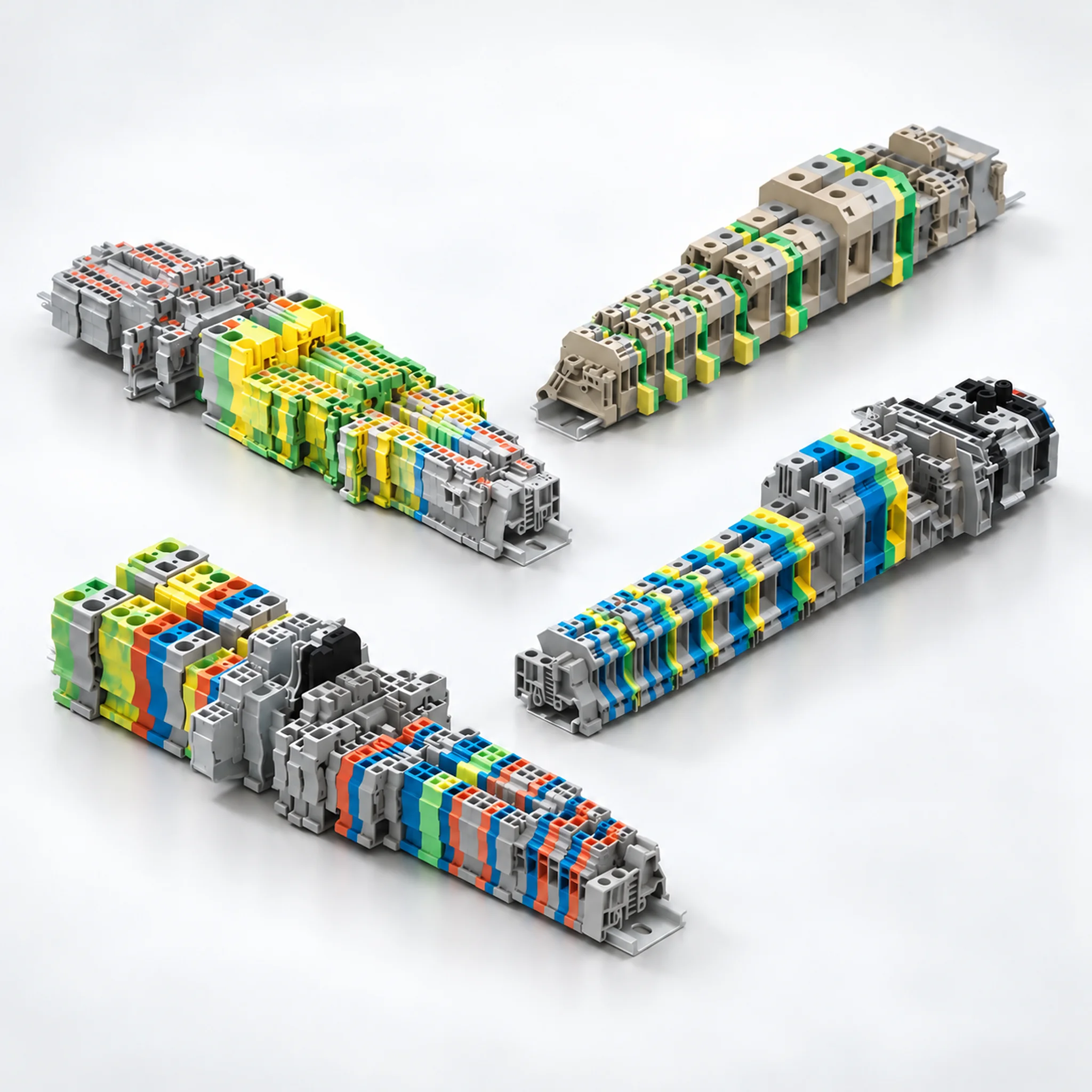
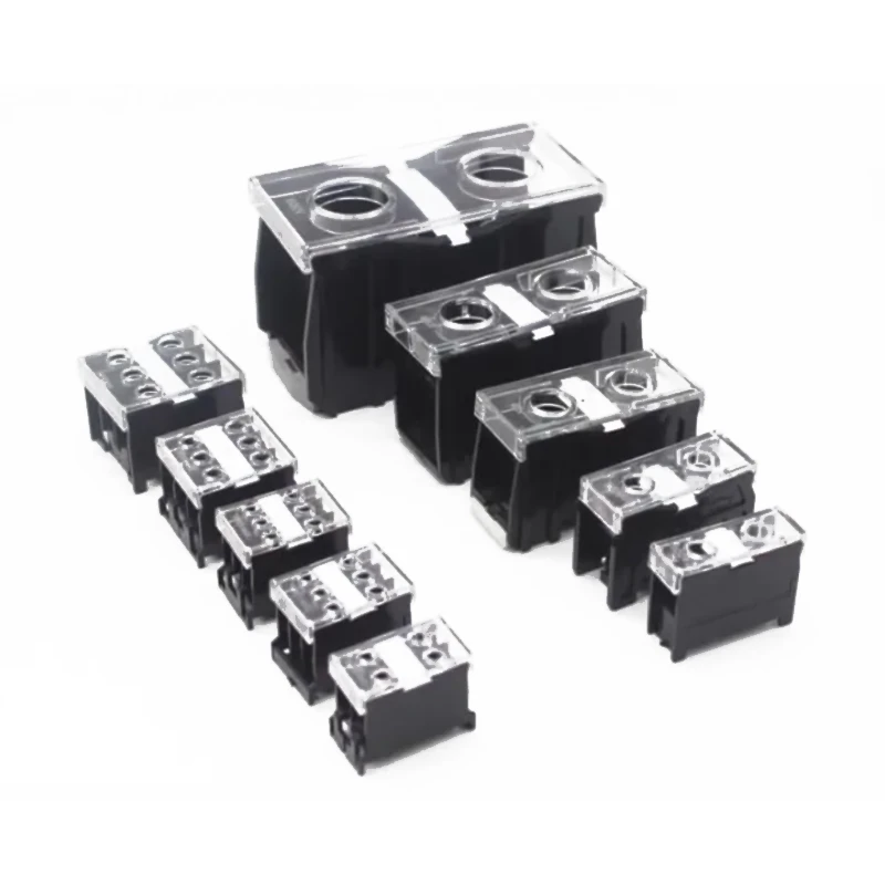
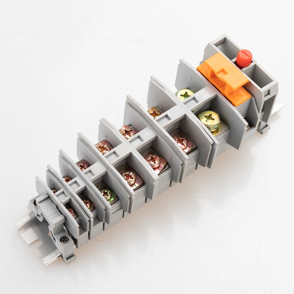
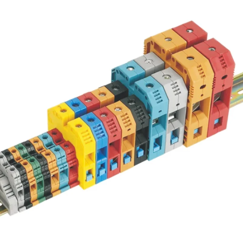
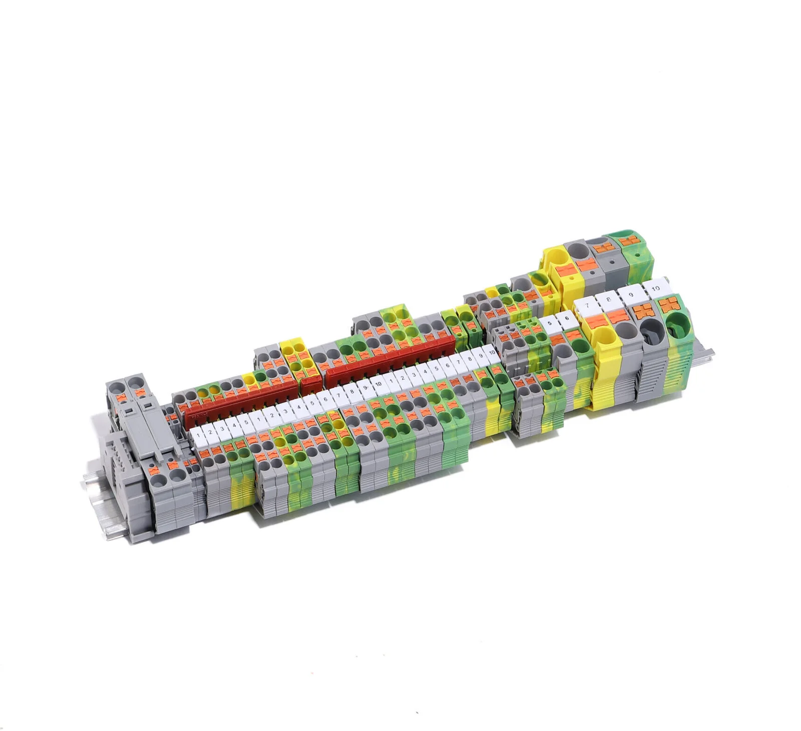
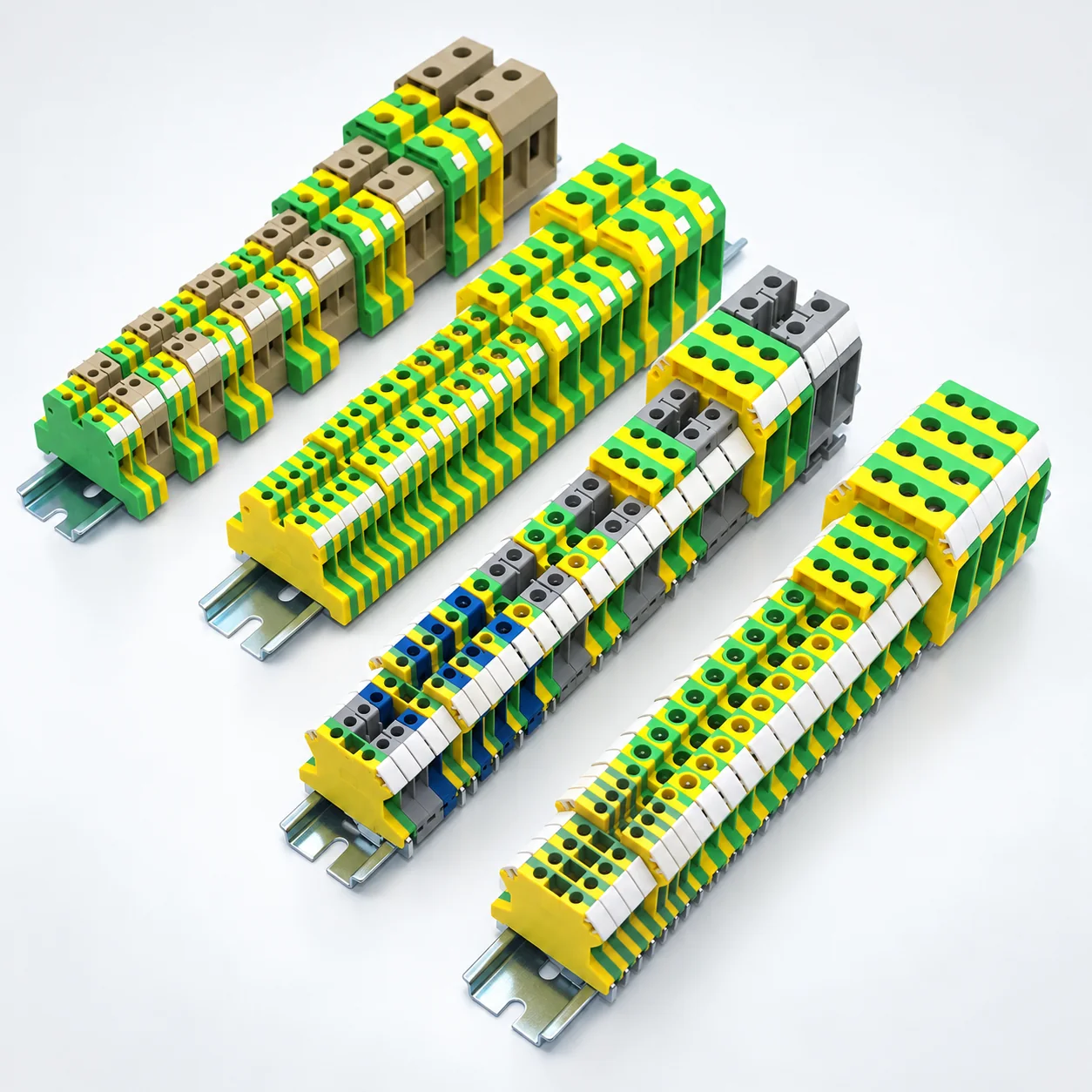
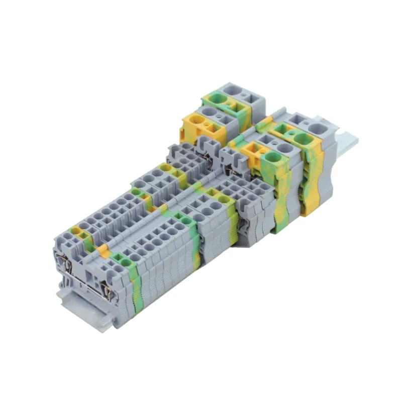
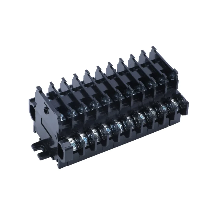
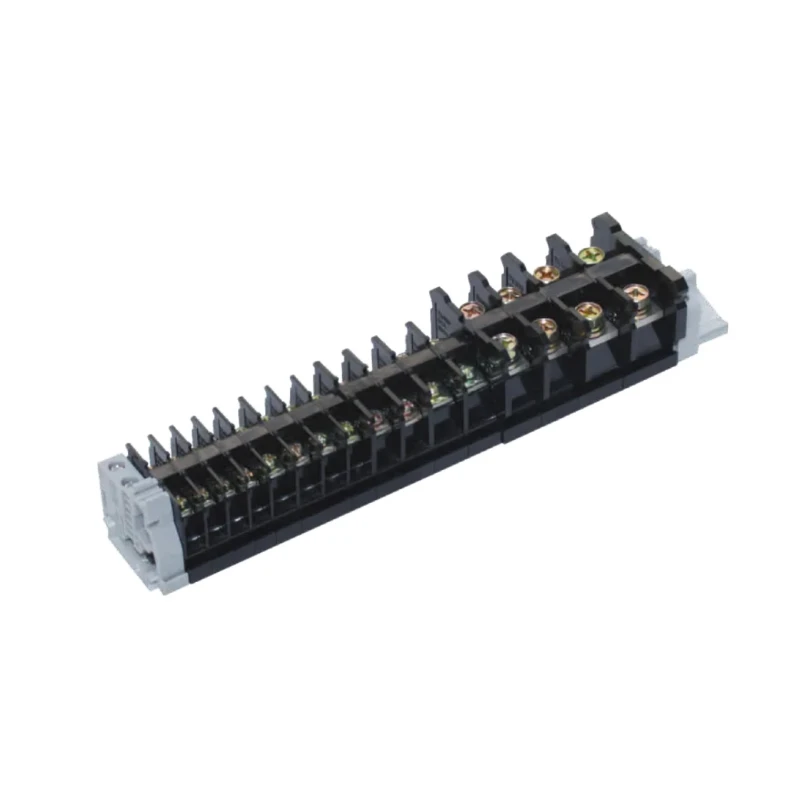
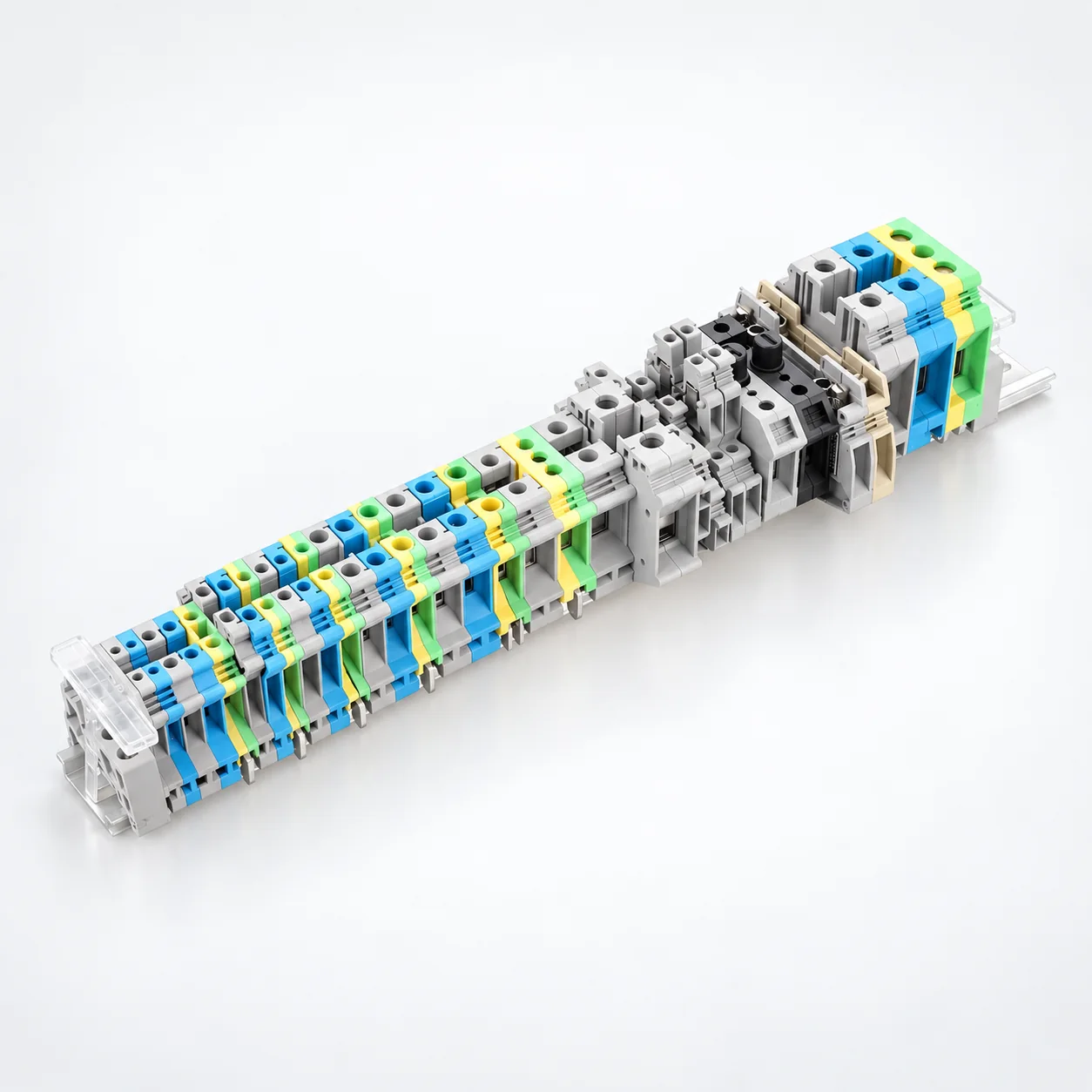
| Construção | Foco na seleção | Referência da série |
|---|---|---|
| PT · Ligação por pressão | 35 modelos listados que cobrem configurações padrão de passagem, TWIN, QUATTRO, multinível e PE. Ligação por pressão para condutores sólidos ou com terminais adequados; pé de montagem NS 35. | Série PT |
| SJ · Mola de gaiola | modelos listados 13, com secções nominais de 1.5 a 16 mm². Montagem TH35-7.5 / TH35-15. As classificações elétricas são especificadas para oito modelos, não para todas as variantes listadas. | Série SJ |
| UK · Borne de parafuso | Os modelos listados 36 incluem bornes standard, compactos, multinível e de terra de proteção. Verifique os intervalos de condutores rígidos/flexíveis e as opções de pontes e placas terminais específicas do modelo. | UK · Modelos USLKG PE |
| SAK · Borne de parafuso | Oito modelos standard, quatro de função especial e seis modelos EK de terra de proteção. Conexões de parafuso tipo frame com intervalos de condutores e dimensões específicas do modelo. | SAK / EK SAK(JXB |
| JH1A · Parafuso | Nove modelos com correntes nominais de 17.5–125 A e classificações 380 V ou 500 V. Reveja a capacidade do condutor, o tamanho do parafuso e o 35 mm ou 28 mm de montagem especificado. | Série JH1A |
| MRK · Conexões de painel | Modelos 11 com secções transversais listadas de 2.5 a 120 mm², correntes individuais de 24–269 A e classificações 750 V ou 1000 V. Montagem por encaixe em calhas 35 mm DIN. | Série MRK |
| TBD · Double-layer screw | Two wiring levels within a shared footprint. Three models rated 10, 20 or 30 A at 600 V, with 35 mm DIN rail mounting. The listed standard arrangement has 10 positions and end plates. | TBD-10A · TBD-20A · TBD-30A |
| TK · Screw | Six models from TK-010 to TK-100 with 10–100 A individual ratings and model-specific conductor sizes spanning 0.75–25 mm². TH35-7.5 mounting; check AC and DC voltage specifications separately. | TK series |
| IN · Screw | Eight models rated 600 V, with individual currents of 20–240 A and wire ranges spanning 0.75–100 mm². Transparent PC covers have tool-access openings. | IN series |
Ranges above summarize different models. Select the conductor capacity, current and voltage from the same product row.
Specify solid or stranded conductors, cross-section, ferrule use and conductors per connection. Check stripping length and permitted preparation for the exact terminal.
Choose push-in, cage spring or screw termination according to the wiring process and selected model. Confirm insertion, release or tightening instructions; do not assume all spring terminals operate identically.
Identify the rail profile and dimensions, terminal width, height and depth. Most listed families include 35 mm mounting options, but JH1A also lists 28 mm rail widths; verify each model.
Distinguish feed-through, PE, multi-level and special-function circuits. Select matching bridges, markers, end plates and end stops, then check model-specific electrical ratings.
Send the terminal series and model, conductor schedule, rail drawing, accessory list and quantities. Include required labels, packing and project documentation.
Prepare um pedido de consultaAcorde a especificação e as provas necessárias antes de efetuar a sua encomenda.
Explorar fabricoList each terminal model, circuit function, conductor type and size, and quantity. Separate feed-through, protective-earth and special-function positions.
Provide the rail profile, usable rail length and panel-space constraints. Include terminal width, end components and access needed for wiring and maintenance.
List series-compatible bridges, end plates, markers and end stops. Specify circuit identification and bridge positions rather than assuming accessories are universal.
State required model documentation, inspection criteria, label artwork, pack quantities and destination. Confirm sample and supply requirements with the quotation.
OEM e EMBALAGEM
Build your din rail terminal blocks order around the selected models, identification and supply requirements.
List each terminal model, circuit function, conductor type and size, and quantity. Separate feed-through, protective-earth and special-function positions.
Forneça os números de peça, a arte da etiqueta e quaisquer informações de lote ou rastreabilidade necessárias para a encomenda.
Especifique as quantidades por modelo, embalagens individuais, caixas exteriores e destino de entrega.
They provide organized conductor termination points in control cabinets and electrical panels. The required model depends on the circuit function, wire capacity, electrical ratings, rail interface and installation space.
The PT range lists push-in connection for suitable solid or ferruled conductors. SJ is a cage spring range. Conductor insertion and release procedures depend on the selected mechanism and model; follow its specific instructions rather than treating both names as interchangeable.
No universal rail fit is claimed. PT specifies NS 35; SJ lists TH35-7.5 and TH35-15; TK lists TH35-7.5. JH1A includes 35 mm and 28 mm rail widths. Confirm the rail interface for your exact model.
They serve different circuit functions. PT includes PE configurations, UK includes USLKG protective-earth models, and SAK includes EK models. Review the intended earth connection and mounting requirements separately; do not apply feed-through current or voltage ratings by assumption.
Do not assume compatibility. Match bridges, end plates, markers and fixing accessories to the terminal model and manufacturer drawing. UK product information identifies model-specific jumper and end-plate options.
It depends on the connection mechanism and approved conductor preparation. Provide the wire type, size and ferrule details, and check the selected terminal's instructions and clamping capacity.
No. A material flammability classification is not certification of the complete terminal block. Request model-specific certification or test evidence where your project requires it.
This page focuses on DIN rail terminal blocks. For dedicated incoming-to-branch power connections such as UKK, K and UTJ5, use the separate Power Distribution Blocks range.
Send the terminal schedule, rail layout, bridge positions, circuit labels and quantities for a feasibility review. Assembly, marking, sample and packing options are confirmed for the requested configuration.
Send the terminal series and model, conductor schedule, rail drawing, accessory list and quantities. Include required labels, packing and project documentation. Include the exact model quantities, delivery destination and required documentation.
Envie os seus números de peça, arte final do rótulo, quantidades de embalagem e requisitos de expedição. A viabilidade, os requisitos de amostra, as quantidades mínimas e o prazo de entrega são confirmados para os modelos solicitados.