
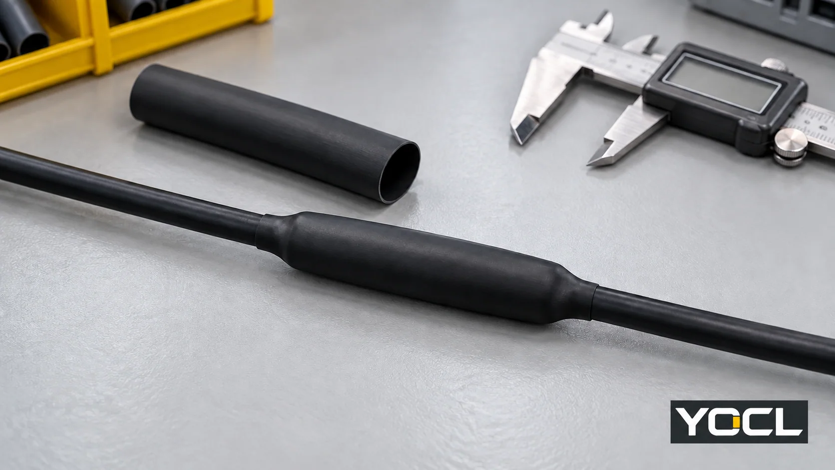
Выберите термоусадочную трубку, которая проходит над самым большим элементом соединения, сжимается до наименьшего диаметра посадки и обеспечивает необходимое покрытие после усадки. Отрежьте и предварительно наденьте ее перед замыканием соединения, примите электрическое соединение, расположите гильзу, усадите ее с помощью указанного процесса нагрева, затем охладите, проверьте и завершите необходимые испытания сборки.
Данная процедура охватывает указанное прямое линейное соединение. Термоусадочная трубка обеспечивает указанную изоляцию или защиту; она не выполняет электрическое соединение. Экранированные, многожильные и средне- или высоковольтные соединения требуют собственных инструкций по сборке. Плотно усаженная гильза не является доказательством того, что соединение электрически приемлемо или герметично.
1. Подтвердите рабочие инструкции и изоляцию
Перед резкой кабеля или применением нагрева получите чертеж соединения, инструкции по соединению, точные данные по трубке, процесс применения и требования к приемке. Работайте на изолированной цепи, проверенной на отсутствие напряжения в соответствии с процедурой оборудования и объекта. На рабочих местах U.S, OSHA 1910.333(b) устанавливает процедуры блокировки/маркировки и проверки квалифицированным лицом.
Используйте запись о работе для связи измерений с окончательным решением о приемке:
| Запись перед началом | Решение, которое оно контролирует |
|---|---|
| Идентификация кабеля/оболочки, соединения и гильзы | Совместимость материалов и применимые инструкции |
| Самая большая особенность на пути вставки гильзы | Требуемый внутренний диаметр в состоянии поставки |
| Внешние диаметры посадки слева и справа | Требуемая усадка с обеих сторон |
| Совместный пролет и указанный нахлест с каждой стороны | Минимальное готовое покрытие |
| Электрическая нагрузка, среда и доступное пространство | Конструкция, пригодность для стен и сборки |
| Инструкции по нагреву, охлаждению и приемке | Пределы процесса и проверки приемки |
Имейте в наличии подходящие измерительные инструменты, резак, указанные инструменты для соединения и разрешенный контролируемый источник тепла. Приостановите работу, если отсутствует требуемая инструкция или критерий приемки.
2. Выберите конструкцию и проверьте оба диаметра
Выберите конструкцию для указанной задачи. Ассортимент термоусаживаемых трубок YOCL включает однослойные трубки HTS и HS3X/HS4X трубки с клеевым слоем. Нелайнированная гильза может выполнять требования по изоляции/защите; гильза с клеевым слоем требует совместимого интерфейса оболочки и проверенного процесса применения при необходимости герметизации. Используйте руководство по однослойным и двухслойным трубкам если это решение остается нерешенным.
Измерьте полный путь вставки, включая любое плечо разъема, которое должна пересекать гильза. Запишите оба посадочных диаметра отдельно; площадь поперечного сечения проводника не является диаметром оболочки. Проверьте указанный минимальный внутренний диаметр на соответствие самому большому проходному элементу, а максимальный внутренний диаметр после восстановления — самому маленькому посадочному.
Принцип «больше до / меньше после» встречается в KSC-E-165 Редакция F, §3.8.1.1.1(a), спецификация для наземного оборудования управления и контроля KSC. Она поддерживает этот размерный экран, а не универсальный монтажный зазор.
Например, предположим 7.4 mm самую большую проходную деталь и 4.0 mm самую маленькую посадку. Текущая YOCL HS3X таблица дает:
| HS3X nominal size | Supplied ID | Recovered ID | Preliminary result |
|---|---|---|---|
| 6.4 mm | ≥6.4 mm | ≤2.2 mm | Guaranteed supplied minimum does not clear 7.4 mm |
| 9.5 mm | ≥9.5 mm | ≤3.2 mm | Clears both basic diameter checks |
The 9.5 mm row is a dimensional candidate, not an approved sealed splice. Confirm the required insertion allowance, tolerances, wall/space, duty and jacket compatibility. Consult the size chart for other rows; use the shrink-ratio comparison when passage and landing geometry demand another ratio.
3. Determine cut length and preload the sleeve
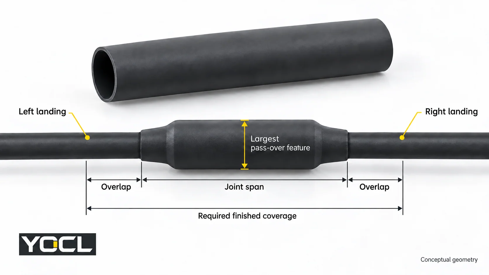
Finished coverage must include the joint span and the specified overlap on each side. Allow for longitudinal change using the applicable process data. Do not substitute an arbitrary extra-length percentage or a laboratory axial-change value for an established installation allowance.
Where the instructions establish a maximum shortening fraction s, a planning calculation is:
Minimum cut length = (joint span + left overlap + right overlap) ÷ (1 − s)
Use the specified overlap and validated s for that application, round up to the permitted cut length, and verify actual coverage after cooling. If those inputs are unknown, the calculation cannot release the sleeve for cutting.
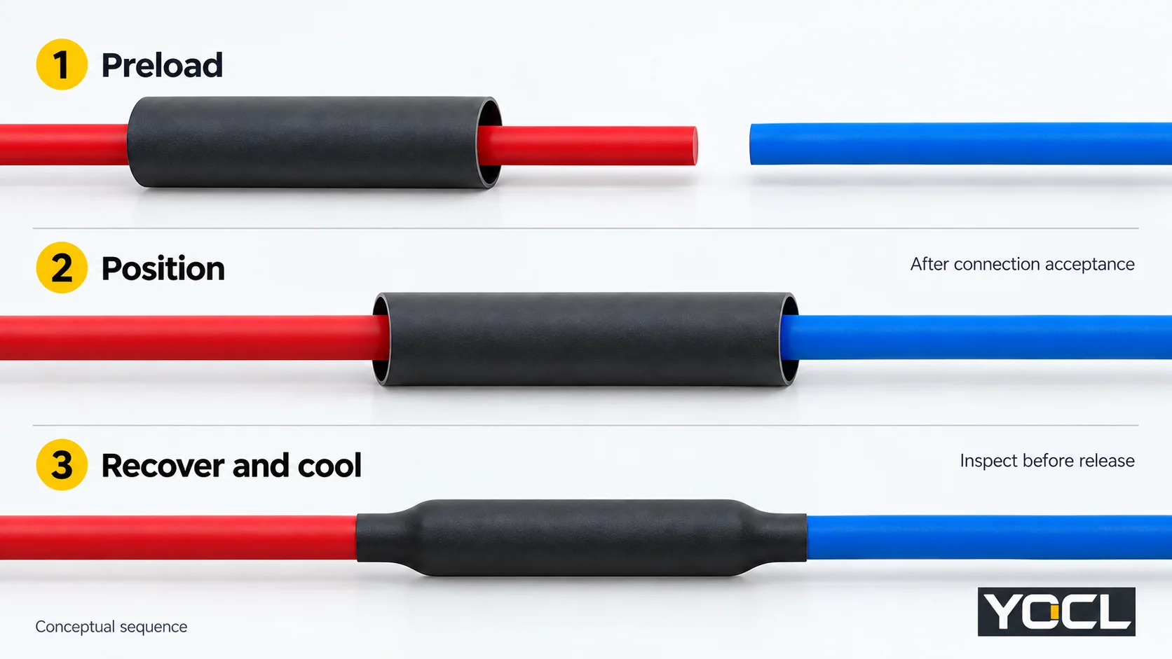
YOCL’s HTS installation notes direct cutting to the required length and sliding tubing on before completing the connection when necessary. Preload the selected sleeve while access remains. Park it clear of the connection-making area under the joining instructions.
If access has been closed without preloading, stop for an approved correction; slitting a standard closed tube does not make it an approved wraparound sleeve.
4. Complete and accept the connection before covering it
Make the splice using its specified connector, conductor combination and joining procedure. Complete the required connection inspection before the sleeve conceals the joint. A failed or undocumented connection remains on hold even if the tubing fits.
Prepare the landing surfaces according to the selected jacket, sleeve and adhesive instructions. If they require cleaning, priming or drying, follow those material-specific directions. Do not improvise a solvent or abrasion method. For an adhesive-lined sealing job, unresolved surface compatibility or preparation means the sleeve is not ready for application.
5. Position the sleeve to the drawing
Move the sleeve into its specified position and check coverage at both ends.
Expected result: the joint and both required landing overlaps lie within the intended finished coverage. Reposition before heating if one end lacks coverage; extra material on the other end does not satisfy that requirement.
6. Recover with the specified heating process
HTS requires uniform recovery with controlled, even heat; other models need their applicable process.
Use the heat source, heating sequence, exposure limits and completion criteria established for the actual assembly. A catalogue shrink temperature is not a heat-gun dial setting, nozzle distance or dwell time. If these process requirements are unresolved, obtain the applicable instructions before heating.
NASA-STD-8739.4A Change 4, §9.9, in its NASA mission-hardware scope, ties heat and exposure to tubing size/type and requires protection of the covered item and nearby heat-sensitive parts. These are useful workmanship boundaries; they do not establish settings for a YOCL splice.
Hold the assembly if the specified recovery cannot be completed within its thermal limits or visible heat damage develops.
7. Cool and inspect the application
Let HTS cool before handling; follow the selected assembly’s cooling and inspection instructions. Check:
- Position and actual finished coverage against the drawing.
- Uniform recovery and grip where required.
- Cracks, punctures, blisters or burned areas, plus damage to the cable jacket.
- Any model-specific adhesive and interface acceptance criteria.
NASA-STD-8739.4A §§9.10–9.11 provide scoped examples of positioning, recovery/grip and visible defect checks. Appearance alone does not establish electrical performance or a complete hidden adhesive bond. An adhesive bead can be a specified local process cue; by itself it does not prove an environmental seal.
Route defects or unresolved sealing to the applicable rework process. The split-or-fail-to-seal guide explains the separate diagnosis task; do not keep reheating without authorized rework instructions.
8. Complete the release record before restoration
Record three separate decisions: connection accepted, sleeve workmanship accepted, и required assembly tests passed. Enter the cable/splice and sleeve identification, measured coverage, process reference and test results. A missing seal-verification requirement cannot be replaced with “looks tight.”
Complete the specified electrical and, where required, environmental acceptance tests using the assembly procedure. Hold failed or incomplete results. Restore service only through the equipment/site authorization process; OSHA 1910.333(b)(2)(v) sets out restoration checks for its U.S. workplace scope.
For YOCL model selection, provide the pass-over dimension, both landing diameters, required coverage, jacket material and duty when requesting the applicable tubing and process documentation. That information turns a catalogue size candidate into a reviewable application choice.
Ссылки
- OSHA — 29 CFR 1910.333, electrical work practices, verification and restoration.
- YOCL — Heat Shrink Tubing, current product families.
- NASA KSC — KSC-E-165 Revision F, §3.8.1.1.1(a), dimensional selection.
- YOCL — HS3X 3:1 Dual-Wall Tubing, supplied/recovered size table.
- YOCL — HTS 2:1 Single-Wall Tubing, Installation Notes.
- NASA — NASA-STD-8739.4A Change 4, §§9.9–9.11, heating and workmanship.