
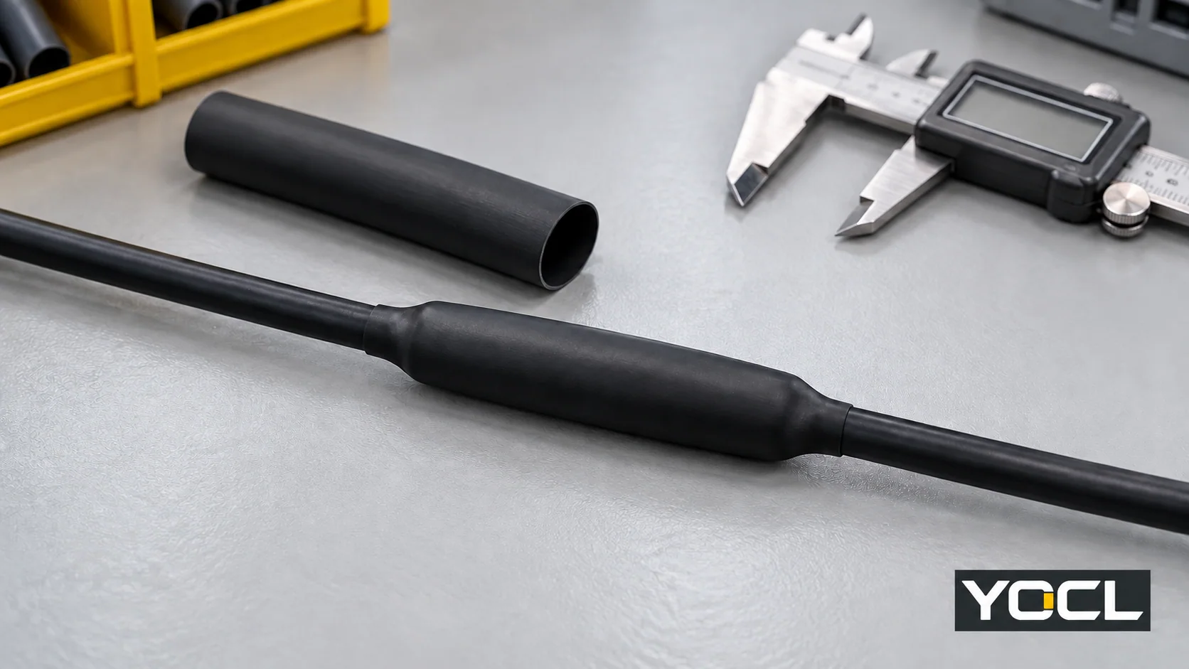
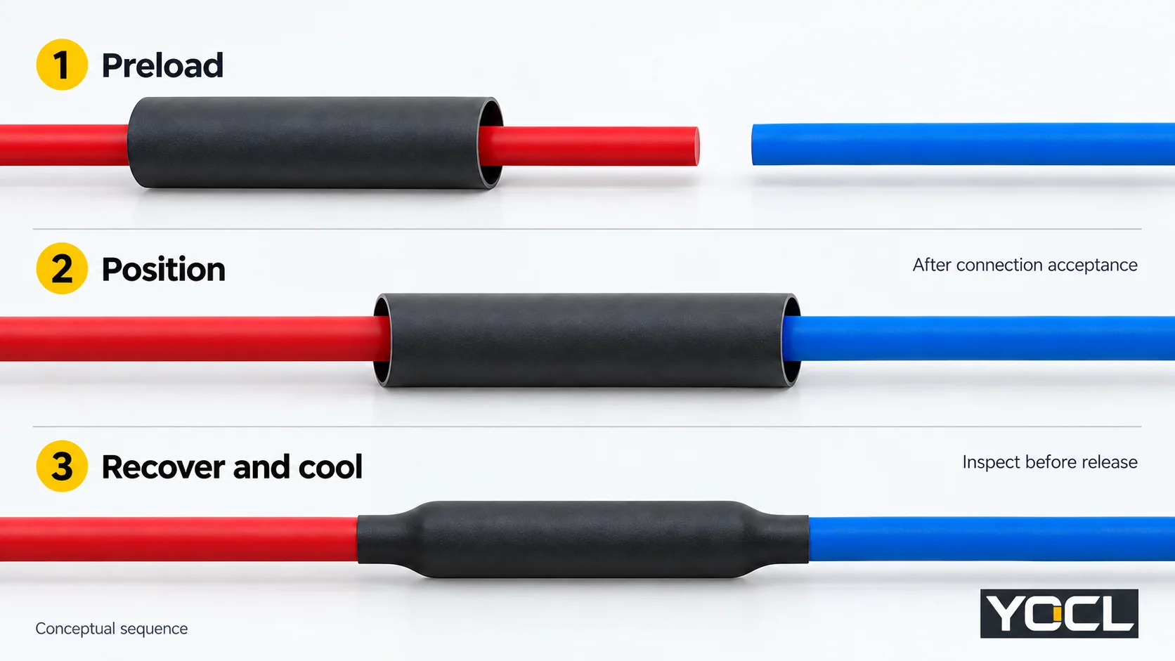
Chọn ống co nhiệt có thể luồn qua phần nối lớn nhất, co lại dưới đường kính tiếp xúc nhỏ nhất và duy trì độ bao phủ cần thiết sau khi co lại. Cắt và luồn sẵn ống trước khi đóng kết nối, chấp nhận mối nối điện, định vị ống, co lại bằng quy trình gia nhiệt được chỉ định, sau đó làm nguội, kiểm tra và hoàn thành các bài kiểm tra lắp ráp cần thiết.
Quy trình này áp dụng cho mối nối thẳng nối tiếp được chỉ định. Ống co nhiệt cung cấp lớp cách điện hoặc bảo vệ được chỉ định; nó không tạo ra kết nối điện. Các mối nối có bọc chống nhiễu, đa lõi và điện áp trung bình hoặc cao cần có hướng dẫn lắp ráp riêng. Ống co chặt không phải là bằng chứng cho thấy mối nối được chấp nhận về điện hoặc được niêm phong môi trường.
1. Xác nhận hướng dẫn công việc và cô lập
Trước khi cắt cáp hoặc áp dụng nhiệt, hãy lấy bản vẽ mối nối, hướng dẫn nối, dữ liệu ống chính xác, quy trình ứng dụng và các yêu cầu chấp nhận. Làm việc trên mạch đã được cô lập và xác minh là không còn điện theo quy trình thiết bị và địa điểm. Tại các U.S nơi làm việc, OSHA 1910.333(b) quy định quy trình khóa/gắn thẻ và xác minh bởi người có chuyên môn.
Sử dụng hồ sơ công việc để liên kết các phép đo với quyết định chấp nhận cuối cùng:
| Ghi lại trước khi bắt đầu | Quyết định nó kiểm soát |
|---|---|
| Nhận dạng cáp/vỏ bọc, mối nối và ống co | Khả năng tương thích vật liệu và hướng dẫn áp dụng |
| Đặc điểm lớn nhất trên đường đi vào của ống co | Đường kính trong được cung cấp yêu cầu |
| Đường kính ngoài tiếp xúc trái và phải | Độ co hồi yêu cầu ở cả hai bên |
| Khoảng cách nối và độ phủ quy định ở mỗi bên | Độ phủ hoàn thiện tối thiểu |
| Chế độ điện, môi trường và không gian có sẵn | Cấu tạo, tường và sự phù hợp của lắp ráp |
| Hướng dẫn gia nhiệt, làm mát và chấp nhận | Giới hạn quy trình và kiểm tra nghiệm thu |
Chuẩn bị sẵn các dụng cụ đo phù hợp, dao cắt, dụng cụ nối quy định và nguồn nhiệt được kiểm soát cho phép. Ngừng công việc nếu thiếu hướng dẫn hoặc tiêu chí chấp nhận bắt buộc.
2. Chọn cấu trúc và kiểm tra cả hai đường kính
Chọn cấu trúc cho nhiệm vụ được chỉ định. Dải ống co nhiệt của YOCL bao gồm ống một lớp và ống lót keo HS3X/HS4X. Ống không lót có thể đáp ứng yêu cầu cách điện/bảo vệ; ống lót keo cần giao diện vỏ tương thích và quy trình ứng dụng đã được xác minh khi cần bịt kín. Sử dụng hướng dẫn ống một lớp so với ống hai lớp nếu quyết định này vẫn chưa được giải quyết.
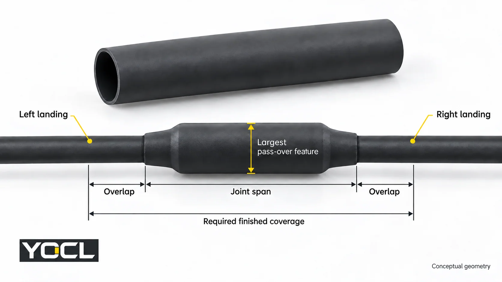
Đo toàn bộ đường đi của vật liệu được lắp, bao gồm cả vai nối mà ống phải đi qua. Ghi lại riêng biệt cả hai đường kính tiếp xúc; diện tích mặt cắt của dây dẫn không phải là đường kính vỏ. Kiểm tra đường kính bên trong tối thiểu được cung cấp so với bộ phận vượt qua lớn nhất và đường kính bên trong tối đa phục hồi so với điểm tiếp xúc nhỏ nhất.
Nguyên tắc lớn hơn trước/nhỏ hơn sau xuất hiện trong KSC-E-165 Bản sửa đổi F, §3.8.1.1.1(a), một thông số kỹ thuật cho thiết bị điều khiển và giám sát hỗ trợ mặt đất KSC. Nó hỗ trợ màn hình kích thước này, không phải là một khoảng lắp đặt phổ quát.
Ví dụ, giả sử một 7.4 mm đặc điểm vượt qua lớn nhất và một 4.0 mm vị trí tiếp đất nhỏ nhất. Bảng YOCL HS3X hiện tại cho kết quả:
| HS3X nominal size | Supplied ID | Recovered ID | Preliminary result |
|---|---|---|---|
| 6.4 mm | ≥6.4 mm | ≤2.2 mm | Guaranteed supplied minimum does not clear 7.4 mm |
| 9.5 mm | ≥9.5 mm | ≤3.2 mm | Clears both basic diameter checks |
The 9.5 mm row is a dimensional candidate, not an approved sealed splice. Confirm the required insertion allowance, tolerances, wall/space, duty and jacket compatibility. Consult the size chart for other rows; use the shrink-ratio comparison when passage and landing geometry demand another ratio.
3. Determine cut length and preload the sleeve
Finished coverage must include the joint span and the specified overlap on each side. Allow for longitudinal change using the applicable process data. Do not substitute an arbitrary extra-length percentage or a laboratory axial-change value for an established installation allowance.
Where the instructions establish a maximum shortening fraction s, a planning calculation is:
Minimum cut length = (joint span + left overlap + right overlap) ÷ (1 − s)
Use the specified overlap and validated s for that application, round up to the permitted cut length, and verify actual coverage after cooling. If those inputs are unknown, the calculation cannot release the sleeve for cutting.
của YOCL HTS installation notes direct cutting to the required length and sliding tubing on before completing the connection when necessary. Preload the selected sleeve while access remains. Park it clear of the connection-making area under the joining instructions.
If access has been closed without preloading, stop for an approved correction; slitting a standard closed tube does not make it an approved wraparound sleeve.
4. Complete and accept the connection before covering it
Make the splice using its specified connector, conductor combination and joining procedure. Complete the required connection inspection before the sleeve conceals the joint. A failed or undocumented connection remains on hold even if the tubing fits.
Prepare the landing surfaces according to the selected jacket, sleeve and adhesive instructions. If they require cleaning, priming or drying, follow those material-specific directions. Do not improvise a solvent or abrasion method. For an adhesive-lined sealing job, unresolved surface compatibility or preparation means the sleeve is not ready for application.
5. Position the sleeve to the drawing
Move the sleeve into its specified position and check coverage at both ends.
Expected result: the joint and both required landing overlaps lie within the intended finished coverage. Reposition before heating if one end lacks coverage; extra material on the other end does not satisfy that requirement.
6. Recover with the specified heating process
HTS requires uniform recovery with controlled, even heat; other models need their applicable process.
Use the heat source, heating sequence, exposure limits and completion criteria established for the actual assembly. A catalogue shrink temperature is not a heat-gun dial setting, nozzle distance or dwell time. If these process requirements are unresolved, obtain the applicable instructions before heating.
NASA-STD-8739.4A Change 4, §9.9, in its NASA mission-hardware scope, ties heat and exposure to tubing size/type and requires protection of the covered item and nearby heat-sensitive parts. These are useful workmanship boundaries; they do not establish settings for a YOCL splice.
Hold the assembly if the specified recovery cannot be completed within its thermal limits or visible heat damage develops.
7. Cool and inspect the application
Let HTS cool before handling; follow the selected assembly’s cooling and inspection instructions. Check:
- Position and actual finished coverage against the drawing.
- Uniform recovery and grip where required.
- Cracks, punctures, blisters or burned areas, plus damage to the cable jacket.
- Any model-specific adhesive and interface acceptance criteria.
NASA-STD-8739.4A §§9.10–9.11 provide scoped examples of positioning, recovery/grip and visible defect checks. Appearance alone does not establish electrical performance or a complete hidden adhesive bond. An adhesive bead can be a specified local process cue; by itself it does not prove an environmental seal.
Route defects or unresolved sealing to the applicable rework process. The split-or-fail-to-seal guide explains the separate diagnosis task; do not keep reheating without authorized rework instructions.
8. Complete the release record before restoration
Record three separate decisions: connection accepted, sleeve workmanship accepted, và required assembly tests passed. Enter the cable/splice and sleeve identification, measured coverage, process reference and test results. A missing seal-verification requirement cannot be replaced with “looks tight.”
Complete the specified electrical and, where required, environmental acceptance tests using the assembly procedure. Hold failed or incomplete results. Restore service only through the equipment/site authorization process; OSHA 1910.333(b)(2)(v) sets out restoration checks for its U.S. workplace scope.
For YOCL model selection, provide the pass-over dimension, both landing diameters, required coverage, jacket material and duty when requesting the applicable tubing and process documentation. That information turns a catalogue size candidate into a reviewable application choice.
Tài liệu tham khảo
- OSHA — 29 CFR 1910.333, electrical work practices, verification and restoration.
- YOCL — Heat Shrink Tubing, current product families.
- NASA KSC — KSC-E-165 Revision F, §3.8.1.1.1(a), dimensional selection.
- YOCL — HS3X 3:1 Dual-Wall Tubing, supplied/recovered size table.
- YOCL — HTS 2:1 Single-Wall Tubing, Installation Notes.
- NASA — NASA-STD-8739.4A Change 4, §§9.9–9.11, heating and workmanship.