
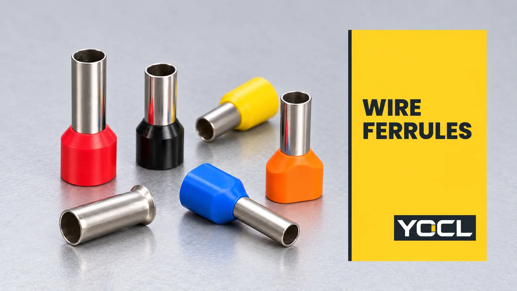
Eine Aderendhülse ist eine rohrförmige Metallhülse, die um die abisolierten Litzen eines Leiters gecrimpt wird, um dessen Ende für den Einstecken in eine kompatible Klemme vorzubereiten. Sie fasst die Litzen zu einem umschlossenen Ende zusammen. Die Klemme stellt weiterhin die Klemmverbindung her; die Art, Größe und endgültige Form der Hülse müssen zu dieser Verbindung passen.
Auch als Kabelschuh, Aderendhülse oder Kabelschuh, bezeichnet, wird diese Komponente durch mehr als nur die Kragenfarbe spezifiziert. Um eine Aderendhülse zu verstehen, trennen Sie ihre Leiterkapazität, Hülsengeometrie und zulässige Verwendung in der Aufnahmebuchse.
Was macht eine Aderendhülse?
Die Metallhülse umgibt die freiliegenden Leiterlitzen. Durch Crimpen wird die Hülse darum geformt, sodass das vorbereitete Ende als ein zusammengefasster Bündel gehandhabt und eingeführt werden kann. Bei einer Version mit Kragen umgibt der kunststoffummantelte Eintritt das Draht-Eintrittsende; der vorstehende Metallteil dringt in den Kontaktbereich des Anschlusses ein.
Der öffentliche Umfang von UL 486F, Aderendhülsen blank und isoliert beschreibt Aderendhülsen als Leiterendvorbereitung, die den Anschluss von Litzen erleichtert und verhindert, dass sich Litzen während des Einführens zurückbiegen. Sie deckt Ausführungen für einen Kupferleiter oder zwei gleiche Größen ab.
Diese Funktion unterscheidet sich von einer an einer Schraube befestigten Öse oder einem Verbinder, der zwei Kabelenden verbindet. Eine Aderendhülse bereitet das Ende für ein anderes Verbindungselement vor. UL 486F trennt Aderendhülsen auch von Stiftadaptern, die von anderen Steckverbindernormen abgedeckt werden; ein ähnlich aussehendes Metallende stellt keine Austauschbarkeit her.
DIN 46228-4:2020-03 identifiziert isolierte Aderendhülsen mit Kunststoffhülse. Die offizielle Einführung erklärt die Litzenaufnahme und das einfachere Einführen in die Klemme. Das unterstützt den Zweck der Komponente, ohne festzulegen, dass jede Klemme eine benötigt.
Die wichtigsten Typen von Aderendhülsen
Die nützlichste erste Unterscheidung ist ein Leiter oder zwei, gefolgt von mit oder ohne Kragen. Der Katalog von YOCL gliedert diese in die Serien E, EN und TE:
| Konstruktion | Sichtbare Anordnung | Was separat geprüft werden muss |
|---|---|---|
| E isolierte Aderendhülse | Eine rohrförmige Hülse mit Isolierkragen | Einzeladergröße, Hülsenlänge und Kragenabstand |
| Unisolierte Einzelader-Aderendhülse | Blankmetallhülse mit aufgeweitetem Eingang | Leitergröße, Hülsendimensionen und die Isolationsanordnung des Geräts |
| TE Isolierte Twin-Aderendhülse | Eine gemeinsame Hülse und ein breiterer Kragen für zwei Leiter | Die Größe jedes Leiters und die Akzeptanz der fertigen Zwei-Leiter-Klemme |
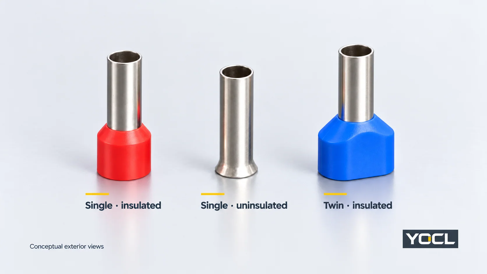
Dies sind YOCL Seriennamen und kein universelles Namenssystem für jeden Lieferanten. “Isoliert” kennzeichnet die Kragenkonstruktion; es liefert keine Spannungsfestigkeit für die fertige Verbindung. Ebenso kennzeichnet “Twin” die vorgesehene Leiteranordnung und nicht die Erlaubnis, zwei Drähte in eine beliebige Klemme einzuführen.
Wie man die Größe einer Aderendhülse liest
Der Leiterquerschnitt unterscheidet sich vom Durchmesser
Eine Bezeichnung wie 1.5 mm² bezieht sich auf den Leiterquerschnitt. Es ist nicht der Außendurchmesser des Kabels, der Innendurchmesser der Hülse oder der Durchmesser ihres Kunststoffkragens.
Read the ferrule’s declared conductor size alongside its drawing. The conductor determines the capacity needed inside the sleeve; the ferrule’s external dimensions affect the space needed at the terminal. Cable insulation and collar geometry add another fit question at the entry.
American Wire Gauge (AWG) is another conductor-size designation. Use the exact AWG or metric sizes declared for the chosen product and conductor. A catalogue pairing is not a reason to assume every nearby AWG/mm² size is an approved substitute.
Sleeve length is different from overall length
Ferrules of the same conductor capacity can have different sleeve lengths. On YOCL’s E-series drawing, F identifies the sleeve-length segment and L the overall length including the collar. These letter labels belong to that drawing; check the exact series before transferring their meanings.
The published E-series und TE-series tables provide a useful example:
| YOCL model | Deklarierte Leiteranordnung | F sleeve length | L overall length |
|---|---|---|---|
| E1508 | One × 1.5 mm² | 8.0 mm | 15.0 mm |
| E1512 | One × 1.5 mm² | 12.0 mm | 19.0 mm |
| TE 1508 | Two × 1.5 mm² | 8.0 mm | 15.5 mm |
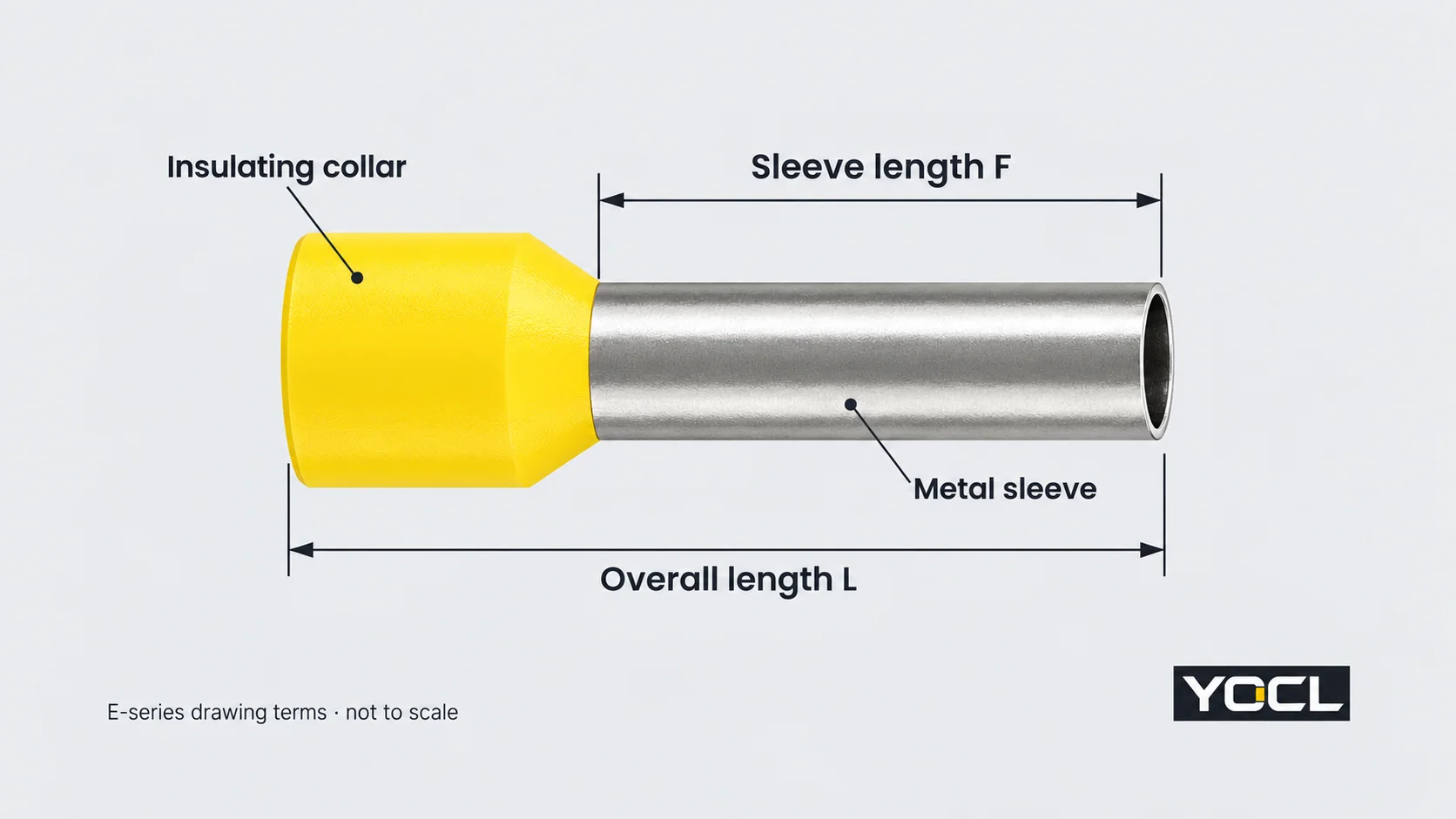
These are catalogue dimensions, not measurements of an installed connection. E1508 and E1512 accept the same declared conductor area but have different lengths. TE 1508 shares an 8 mm F dimension with E1508 while describing a different conductor arrangement. Neither area nor sleeve length alone determines terminal compatibility.
The receiving terminal’s insertion depth and preparation instructions determine which length is appropriate. Overall length cannot substitute for sleeve length when comparing the metal portion with the terminal’s contact space.
Twin notation and collar colour need their own reading
2 × 1.5 mm² means two conductors, each 1.5 mm². Their nominal areas add to 3 mm², but that arithmetic does not turn the twin ferrule into a single-wire 3 mm² model. Entry geometry, sleeve capacity, tooling and the permitted terminal arrangement remain separate requirements.
Colour is useful only within the specified catalogue coding. YOCL’s E-series lists colour options by size group. Its TE 7508 and TE 7510 models both declare 2 × 0.75 mm², yet list blue and grey collars respectively. Confirm the model and conductor designation rather than selecting a ferrule from colour alone.
What makes a ferrule compatible with a terminal?
Compatibility involves three interfaces:
- Conductor to ferrule: the conductor material, size and count must match the ferrule’s declared arrangement.
- Ferrule to crimping tool: the applicable tool and die must produce the required termination for that ferrule. Tool capacity alone does not establish the correct finished profile.
- Finished ferrule to terminal: the receiving device must permit the prepared conductor arrangement and accommodate its sleeve, crimp profile and collar.
“Screw terminal”, “spring terminal” and “push-in terminal” name connection mechanisms. They do not provide a universal answer to whether a ferrule is required, optional or unsuitable. Use the exact device’s instructions and any declared range for ferruled conductors. A ferrule that physically enters the opening has passed only a geometry check.
There is also an explicit scope boundary: UL 486F’s public scope excludes insulation-displacement connection (IDC) terminal blocks. Do not treat a prepared metal sleeve as a general replacement for the insulated wire that an IDC contact is designed to engage.
For a twin ferrule, verify acceptance of the two-conductor arrangement and its finished dimensions. A larger opening, a sufficient nominal area or a broad plastic collar cannot supply that authorization. Square and hexagonal crimp names also need to be checked against the actual ferrule, tooling and terminal documentation; neither is a universal compatibility rule.
What do standards and certification tell you?
Standard identity, product dimensions and connection approval answer different questions. DIN’s published title identifies a construction family; UL 486F’s public scope identifies its intended use and exclusions. A supplier’s reference to either standard is not, by itself, a model-specific certification record.
UL Solutions’ explanation of Component Recognition distinguishes a component’s assessment from certification of a complete end product. Recognized components have conditions of acceptability governing their use. Where certification is required, check the exact product record and applicable conditions alongside the receiving equipment’s documentation.
The YOCL dimensions above are first-party product declarations. They help interpret size fields; this article does not assert UL certification, a current rating or an approved terminal combination for those models.
Which document should you check next?
| Ihre Frage | The next document to use |
|---|---|
| Which construction describes the part I need? | The single, bare or twin product-family information |
| What conductor does this model accept? | Its declared conductor size, material and count |
| What do its length and diameter fields mean? | The exact model/series drawing and dimension table |
| Which tool produces the required crimp? | The applicable ferrule and tooling instructions |
| Is the prepared end permitted in my terminal? | The exact receiving device’s wiring instructions and connection data |
| What evidence covers the intended equipment or market? | Relevant model certification records, conditions and equipment requirements |
Das YOCL wire-ferrule catalogue routes these construction and dimension questions to the E, EN and TE product information. When asking for a model review, include the conductor size and count, required sleeve length and receiving terminal reference so the enquiry describes the complete interface.
Referenzen
- UL Standards & Engagement — UL 486F: Bare and Covered Ferrules, Edition 3, 2024, revised August 2026. Official public scope, §§1.2, 1.6 and 1.8; function, conductor arrangement and exclusions.
- DIN Media — DIN 46228-4:2020-03: Tubular end-sleeves with plastic sleeve. Official publication identity and public introduction; the paid full standard was not consulted.
- YOCL Produktinformationen — E-Serie Isolierte Aderendhülsen. Construction, model dimensions, drawing and declared colour options.
- YOCL Produktinformationen — EN Unisolierte Aderendhülsen. Bare flared-entry construction and dimension fields.
- YOCL Produktinformationen — TE Twin-Aderendhülsen. Two-conductor notation, model dimensions and model-specific collar colours.
- UL Solutions — The UL Component Recognition Classification. Component conditions of acceptability and the end-product certification boundary.