
Conductor & preparation
Specify solid or stranded conductors, cross-section, ferrule use and conductors per connection. Check stripping length and permitted preparation for the exact terminal.
DIN Reiheneinbauklemmen für Schaltschrank- und Elektroinstallationsverdrahtung. Vergleichen Sie PT-Push-in-, SJ-Käfigzugfeder- und Schraubklemmenreihen, einschließlich Durchgangs-, Mehrstock- und Schutzleiteroptionen. Erstellen Sie eine Klemmenbelegung basierend auf Ihren Leitergrößen, Stromkreisanforderungen und Ihrem Schienenlayout.
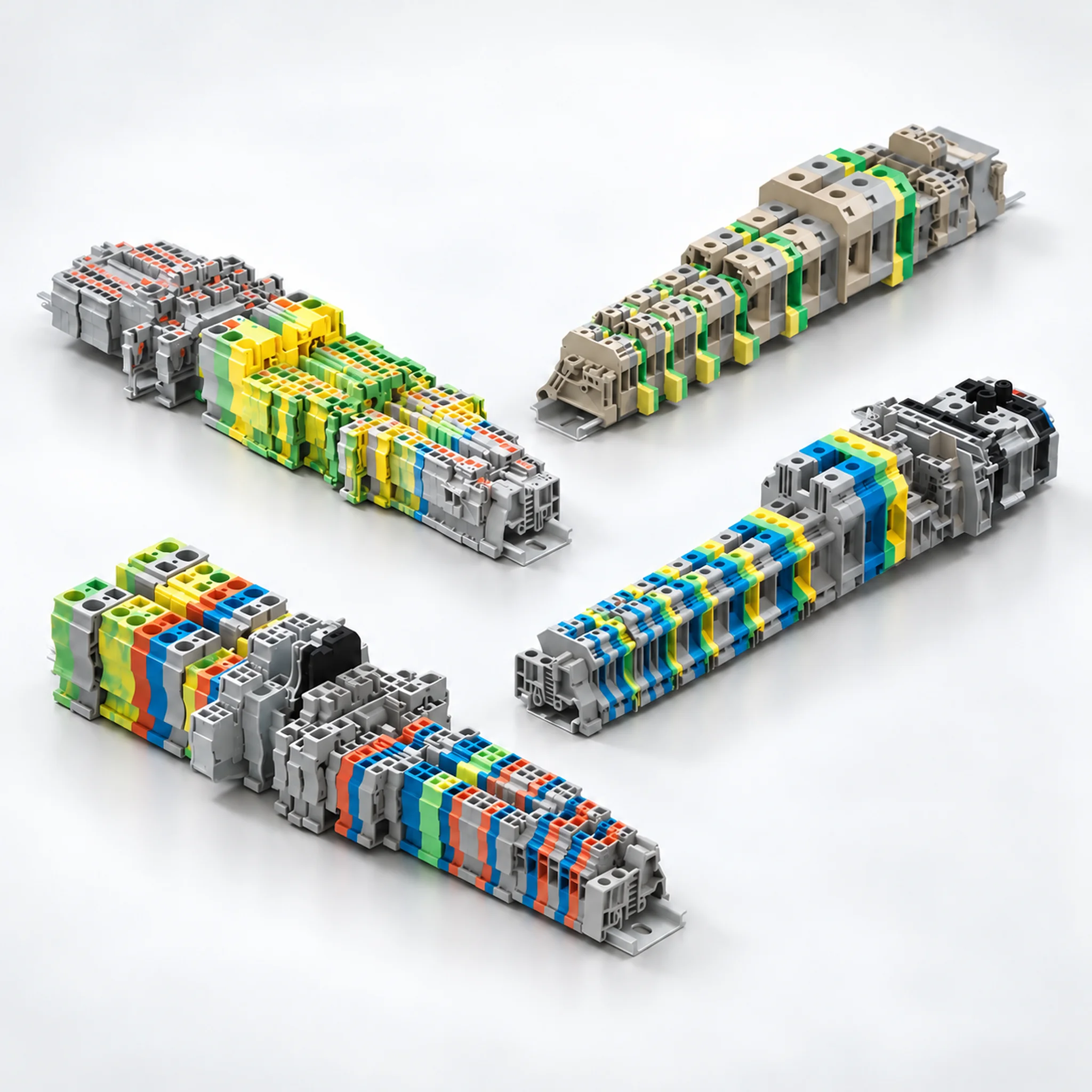
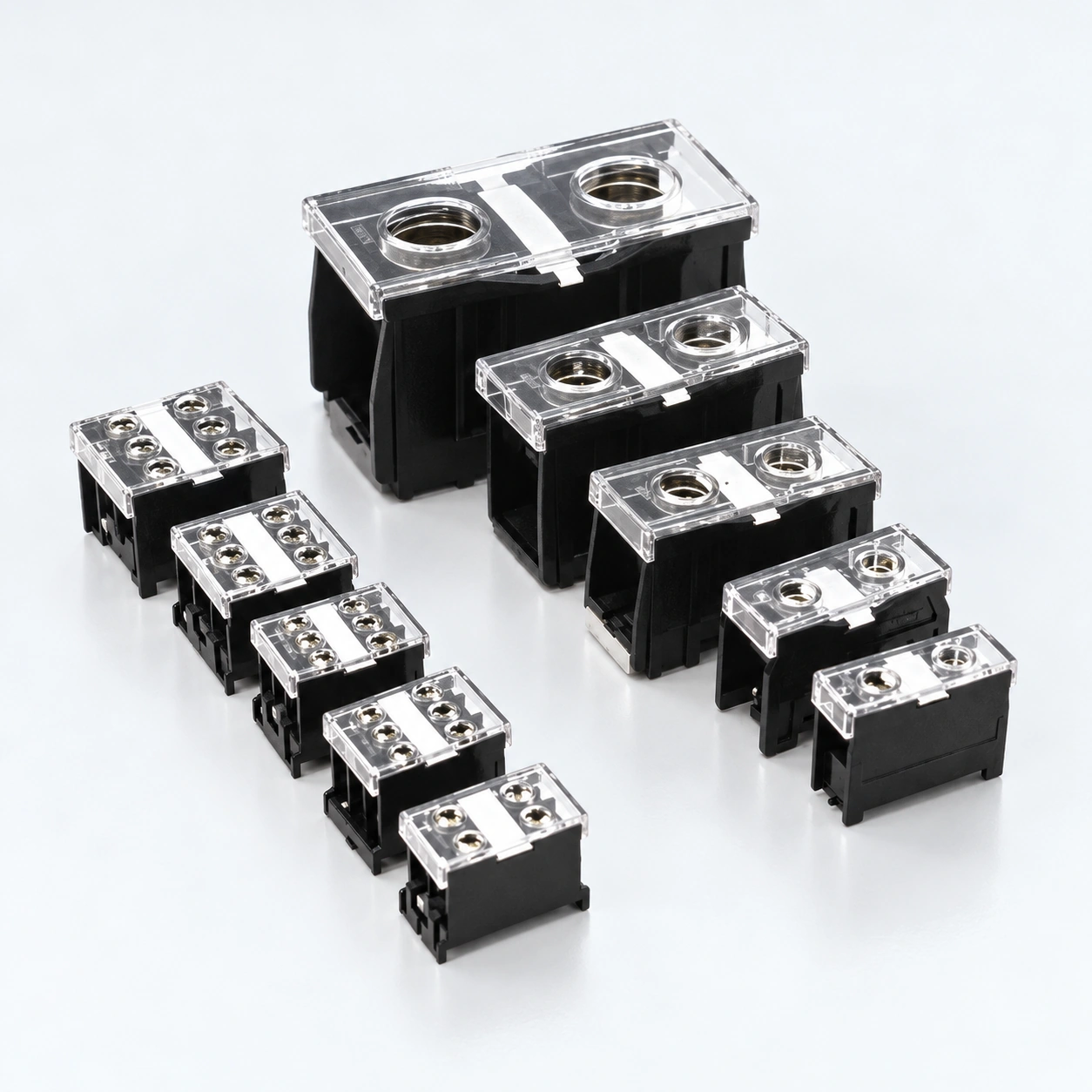
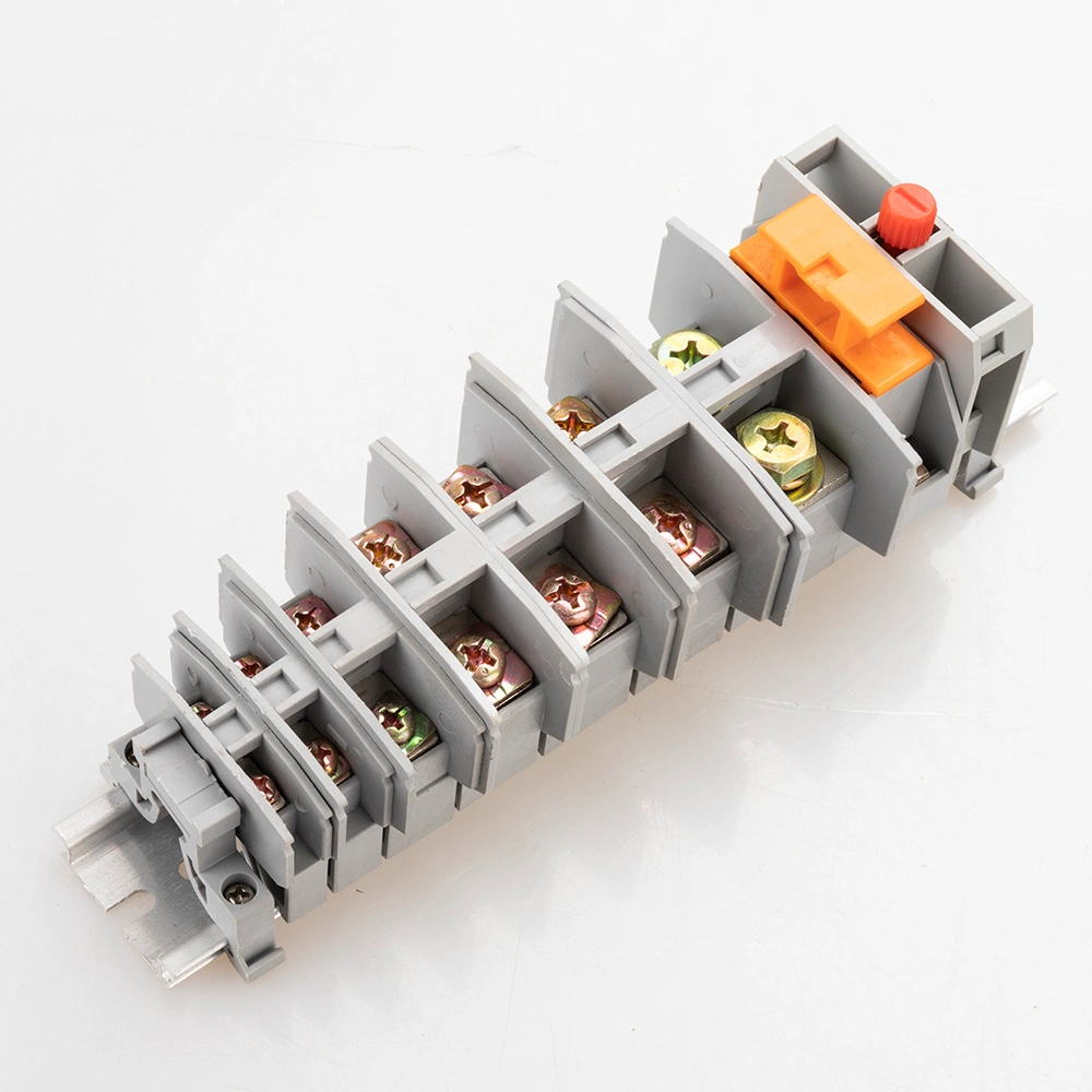
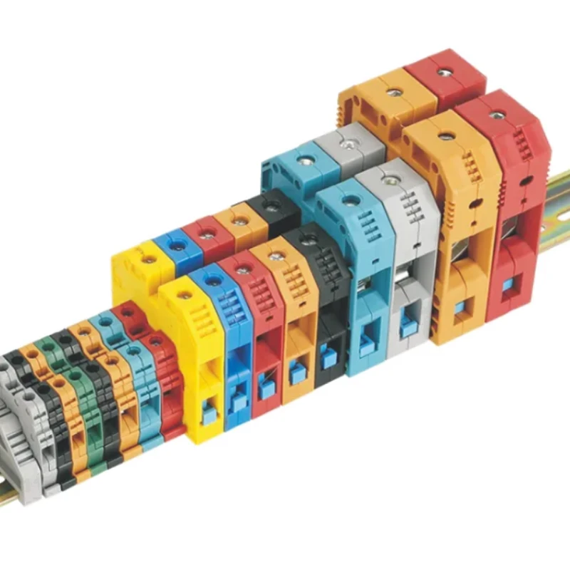
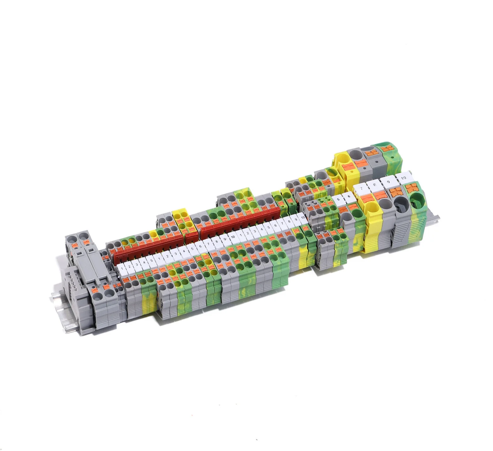
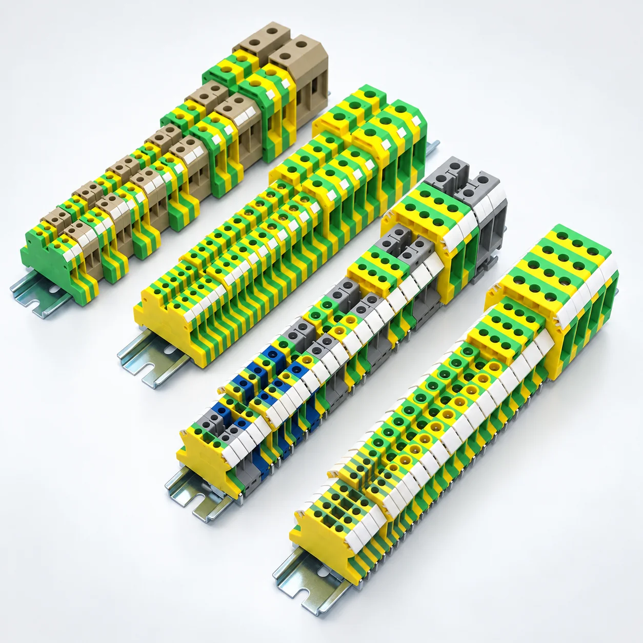
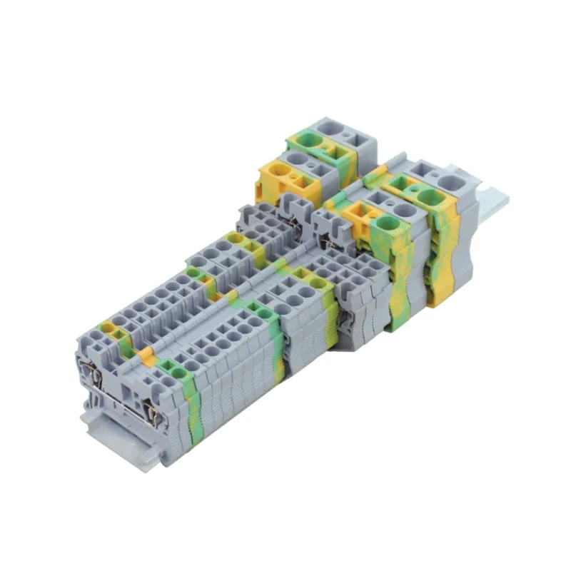
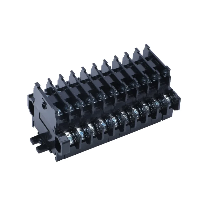
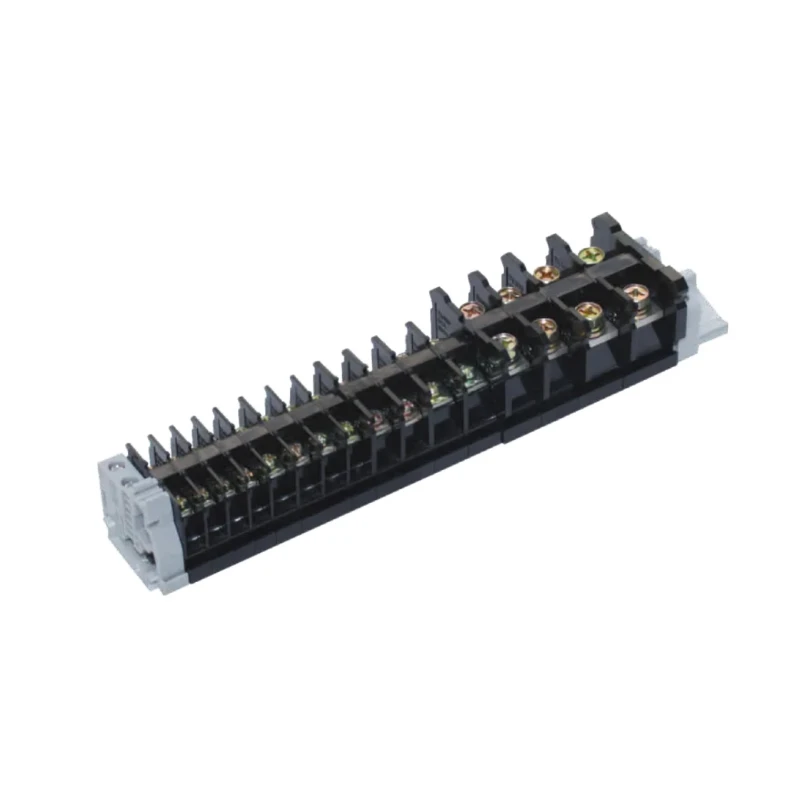
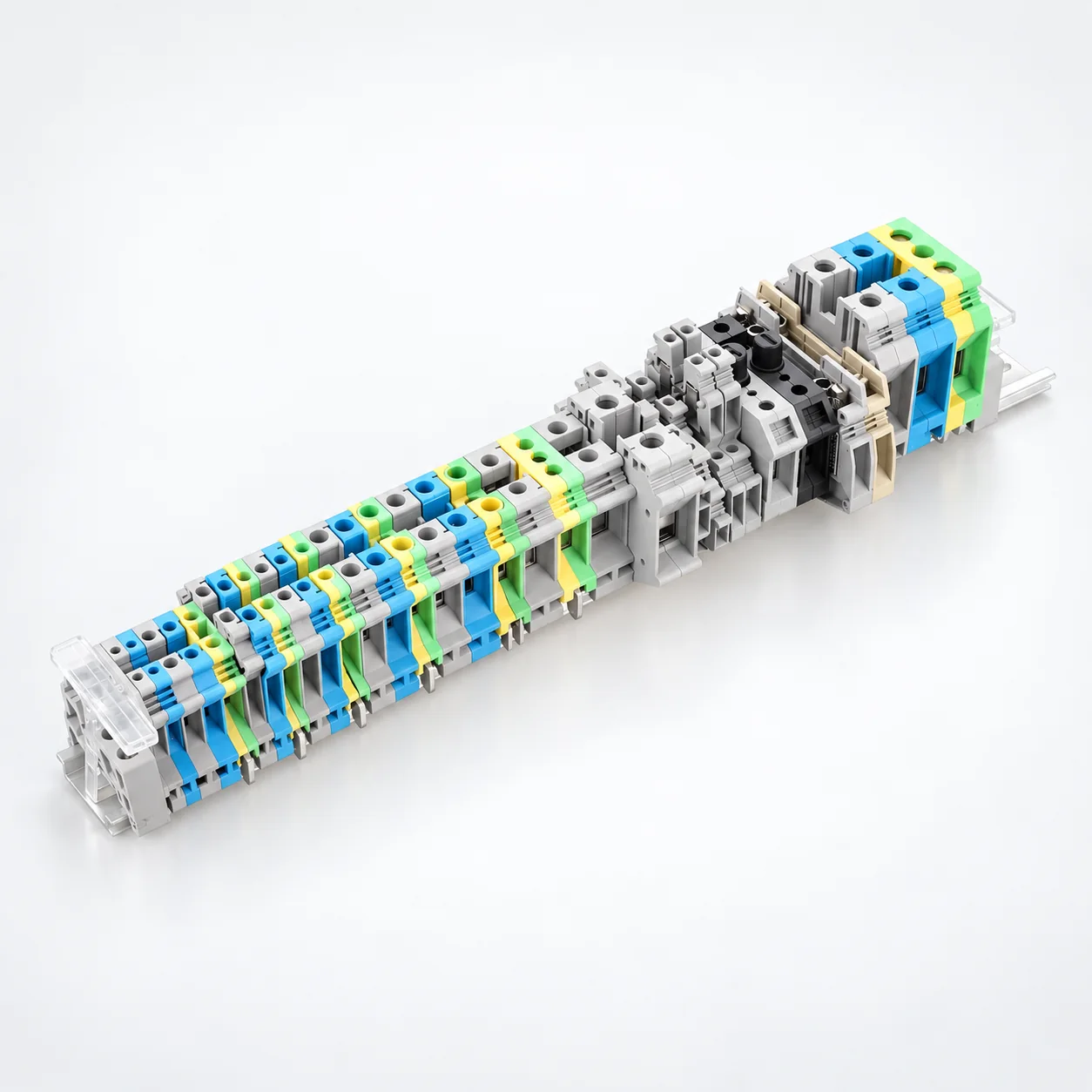
| Konstruktion | Auswahlfokus | Serienreferenz |
|---|---|---|
| PT · Push-in | 35 gelistete Modelle, die Standard-Durchgangs-, TWIN-, QUATTRO-, Mehrstock- und PE Konfigurationen abdecken. Push-in-Anschluss für geeignete massive oder Aderendhülsen-Leiter; NS 35 Montagefuß. | PT-Serie |
| SJ · Käfigzugfeder | 13 aufgeführte Modelle mit Nennquerschnitten von 1.5 bis 16 mm². TH35-7.5 / TH35-15 Montage. Elektrische Nennwerte sind für acht Modelle angegeben, nicht für jede aufgeführte Variante. | SJ-Serie |
| UK · Schraubklemme | 36 aufgeführte Modelle umfassen Standard-, Kompakt-, Mehrstock- und Schutzleiterklemmen. Prüfen Sie die Bereiche für massive/flexible Leiter und die modellspezifischen Optionen für Brücken und Endplatten. | UK · USLKG PE Modelle |
| SAK · Schraubklemme | Acht Standard-, vier Sonderfunktions- und sechs EK-Schutzleiterklemmen. Rahmenklemmen mit modellspezifischen Leiterbereichen und Abmessungen. | SAK / SAK(JXB) · EK |
| JH1A · Schraube | Neun Modelle mit Nennströmen von 17.5–125 A und 380 V oder 500 V-Ratings. Beachten Sie die Leiterkapazität, die Schraubengröße und die angegebene 35 mm oder 28 mm-Montageschiene. | Serie JH1A |
| MRK · Schaltschrankverbindungen | 11 Modelle mit Querschnitten von 2.5 bis 120 mm², Einzelströmen von 24–269 A und 750 V oder 1000 V-Ratings. Schnappmontage auf 35 mm DIN-Schienen. | MRK-Serie |
| TBD · Doppellagige Schraube | Zwei Verdrahtungsebenen innerhalb eines gemeinsamen Footprints. Drei Modelle mit Ratings von 10, 20 oder 30 A bei 600 V, mit 35 mm DIN-Schienenmontage. Die angegebene Standardanordnung hat 10 Positionen und Endplatten. | TBD-10A · TBD-20A · TBD-30A |
| TK · Schraube | Sechs Modelle von TK-010 bis TK-100 mit 10–100 A Einzelbewertungen und modellspezifischen Leitergrößen von 0.75–25 mm². TH35-7.5 Montage; prüfen Sie die AC und DC Spannungsspezifikationen separat. | TK-Serie |
| IN · Schraube | Acht Modelle mit einer Nennleistung von 600 V, Einzelströmen von 20–240 A und Drahtbereichen von 0.75–100 mm². Transparente PC Abdeckungen haben werkzeugzugängliche Öffnungen. | IN-Serie |
Ranges above summarize different models. Select the conductor capacity, current and voltage from the same product row.
Specify solid or stranded conductors, cross-section, ferrule use and conductors per connection. Check stripping length and permitted preparation for the exact terminal.
Choose push-in, cage spring or screw termination according to the wiring process and selected model. Confirm insertion, release or tightening instructions; do not assume all spring terminals operate identically.
Identify the rail profile and dimensions, terminal width, height and depth. Most listed families include 35 mm mounting options, but JH1A also lists 28 mm rail widths; verify each model.
Distinguish feed-through, PE, multi-level and special-function circuits. Select matching bridges, markers, end plates and end stops, then check model-specific electrical ratings.
Send the terminal series and model, conductor schedule, rail drawing, accessory list and quantities. Include required labels, packing and project documentation.
Erstellen Sie eine AnfrageVereinbaren Sie die Spezifikation und die erforderlichen Nachweise, bevor Sie Ihre Bestellung aufgeben.
Fertigung erkundenList each terminal model, circuit function, conductor type and size, and quantity. Separate feed-through, protective-earth and special-function positions.
Provide the rail profile, usable rail length and panel-space constraints. Include terminal width, end components and access needed for wiring and maintenance.
List series-compatible bridges, end plates, markers and end stops. Specify circuit identification and bridge positions rather than assuming accessories are universal.
State required model documentation, inspection criteria, label artwork, pack quantities and destination. Confirm sample and supply requirements with the quotation.
OEM & VERPACKUNG
Build your din rail terminal blocks order around the selected models, identification and supply requirements.
List each terminal model, circuit function, conductor type and size, and quantity. Separate feed-through, protective-earth and special-function positions.
Geben Sie Teilenummern, Etikettengrafiken und alle für die Bestellung erforderlichen Chargen- oder Rückverfolgbarkeitsinformationen an.
Geben Sie die Stückzahlen pro Modell, Einzelverpackungen, Außenkartons und den Lieferort an.
They provide organized conductor termination points in control cabinets and electrical panels. The required model depends on the circuit function, wire capacity, electrical ratings, rail interface and installation space.
The PT range lists push-in connection for suitable solid or ferruled conductors. SJ is a cage spring range. Conductor insertion and release procedures depend on the selected mechanism and model; follow its specific instructions rather than treating both names as interchangeable.
No universal rail fit is claimed. PT specifies NS 35; SJ lists TH35-7.5 and TH35-15; TK lists TH35-7.5. JH1A includes 35 mm and 28 mm rail widths. Confirm the rail interface for your exact model.
They serve different circuit functions. PT includes PE configurations, UK includes USLKG protective-earth models, and SAK includes EK models. Review the intended earth connection and mounting requirements separately; do not apply feed-through current or voltage ratings by assumption.
Do not assume compatibility. Match bridges, end plates, markers and fixing accessories to the terminal model and manufacturer drawing. UK product information identifies model-specific jumper and end-plate options.
It depends on the connection mechanism and approved conductor preparation. Provide the wire type, size and ferrule details, and check the selected terminal's instructions and clamping capacity.
No. A material flammability classification is not certification of the complete terminal block. Request model-specific certification or test evidence where your project requires it.
This page focuses on DIN rail terminal blocks. For dedicated incoming-to-branch power connections such as UKK, K and UTJ5, use the separate Power Distribution Blocks range.
Send the terminal schedule, rail layout, bridge positions, circuit labels and quantities for a feasibility review. Assembly, marking, sample and packing options are confirmed for the requested configuration.
Send the terminal series and model, conductor schedule, rail drawing, accessory list and quantities. Include required labels, packing and project documentation. Include the exact model quantities, delivery destination and required documentation.
Senden Sie Ihre Teilenummern, Etikettengrafiken, Packmengen und Versandvorgaben. Machbarkeit, Musteranforderungen, Mindestmengen und Lieferzeiten werden für die angeforderten Modelle bestätigt.