
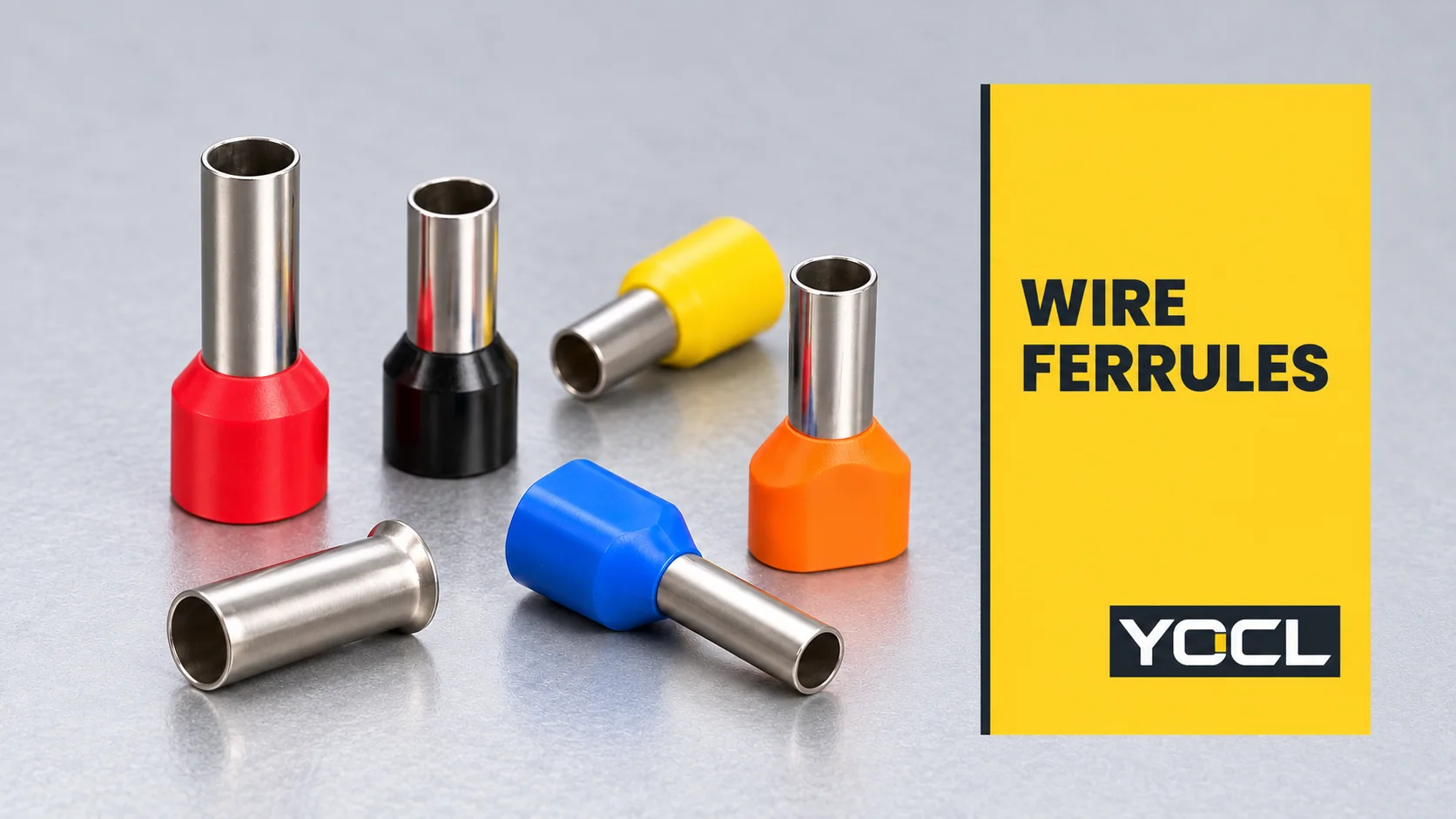
Bir tel yüksük, uyumlu bir terminale takılmaya hazır hale getirmek için bir iletkenin sıyrılmış tellerinin etrafına sıkıştırılmış tübüler bir metal kılıftır. Telleri tek bir uçta toplar. Terminal hala sıkıştırma bağlantısını sağlar; yüksüğün türü, boyutu ve bitmiş şekli bu bağlantıya uygun olmalıdır.
Ayrıca bot bağcığı yüksüğü, tel ucu kılıfı veya kordon ucu yüksüğü, olarak da adlandırılan bu bileşen, yaka renginden daha fazlasıyla belirtilir. Bir yüksüğü anlamak için, iletken kapasitesini, kılıf geometrisini ve alınan terminaldeki izin verilen kullanımını ayırın.
Tel yüksük ne işe yarar?
Metal kovan, açıkta kalan iletken tellerini çevreler. Sıkma işlemi, hazırlanan ucun tek bir paketlenmiş demet olarak tutulup takılabilmesi için kovanı etraflarına şekillendirir. Yakalı bir versiyonda, plastik giriş tel giriş ucunu çevreler; çıkıntı yapan metal kısım terminalin temas alanına girer.
Halka açıklığı UL 486F, Ham ve Kaplamalı Yüksükler yüksükleri, tel bağlantısını kolaylaştıran ve tellerinin takma sırasında geri dönmesini önleyen iletken ucu hazırlığı olarak tanımlar. Tek bir bakır tel veya aynı boyutta iki tel için tasarımları kapsar.
Bu işlev, bir saplamaya cıvatalanmış bir pabucun veya iki kablo ucunu birleştiren bir konektörün işlevinden farklıdır. Bir yüksük, ucu başka bir bağlantı cihazı için hazırlar. UL 486F ayrıca yüksükleri, diğer konektör standartları tarafından kapsanan pim adaptörlerinden ayırır; benzer görünümlü metal bir uç, değiştirilebilirliği sağlamaz.
DIN 46228-4:2020-03 plastik kollu, boru şeklinde uç kovanlarını tanımlar. Resmi tanıtımı, tel tutmayı ve daha kolay terminal takmayı açıklar. Bu, bileşenin amacını destekler, ancak her terminalin bir tane gerektirdiğini belirtmez.
Ana tel yüksük türleri
En kullanışlı ilk ayrım şudur: tek iletken veya iki, ardından yakalı veya yakasız yapı. YOCL’nin kataloğu bunları E, EN ve TE serilerine ayırır:
| Yapı | Görünür düzenleme | Ayrı olarak kontrol edilmesi gerekenler |
|---|---|---|
| E yalıtımlı tek telli yüksük | Yalıtım yakalı tek tübüler kılıf | Tek iletken boyutu, kovan uzunluğu ve yaka boşluğu |
| EN yalıtımsız tek telli yüksük | Genişletilmiş girişli çıplak metal kovan | İletken boyutu, tüp boyutları ve ekipmanın yalıtım düzenlemesi |
| TE yalıtımlı çift telli yüksük | İki iletken için ortak bir kovan ve daha geniş bir yaka | Her iletkenin boyutu ve tamamlanmış iki telli sonlandırmanın kabulü |
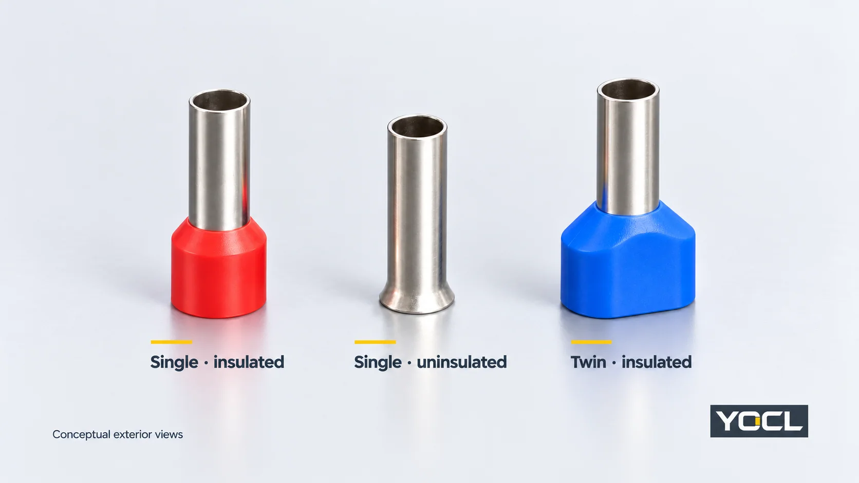
Bunlar, her tedarikçi için evrensel bir adlandırma sistemi yerine YOCL serisi adlarıdır. “Yalıtımlı” yaka yapısını tanımlar; tamamlanmış bağlantı için bir voltaj derecesi sağlamaz. Benzer şekilde, “çift” amaçlanan iletken düzenini tanımlar, herhangi bir terminale iki tel takma izni yerine.
Tel yüksük boyutu nasıl okunur
İletken alanı çaptan farklıdır
Gibi bir gösterim 1.5 mm² iletken kesit alanına atıfta bulunur. Kablonun dış çapı, yüksüğün iç çapı veya plastik yakasının çapı değildir.
Read the ferrule’s declared conductor size alongside its drawing. The conductor determines the capacity needed inside the sleeve; the ferrule’s external dimensions affect the space needed at the terminal. Cable insulation and collar geometry add another fit question at the entry.
American Wire Gauge (AWG) is another conductor-size designation. Use the exact AWG or metric sizes declared for the chosen product and conductor. A catalogue pairing is not a reason to assume every nearby AWG/mm² size is an approved substitute.
Sleeve length is different from overall length
Ferrules of the same conductor capacity can have different sleeve lengths. On YOCL’s E-series drawing, F identifies the sleeve-length segment and L the overall length including the collar. These letter labels belong to that drawing; check the exact series before transferring their meanings.
The published E-series ve TE-series tables provide a useful example:
| YOCL model | Beyan edilen iletken düzenlemesi | F sleeve length | L overall length |
|---|---|---|---|
| E1508 | One × 1.5 mm² | 8.0 mm | 15.0 mm |
| E1512 | One × 1.5 mm² | 12.0 mm | 19.0 mm |
| TE 1508 | Two × 1.5 mm² | 8.0 mm | 15.5 mm |
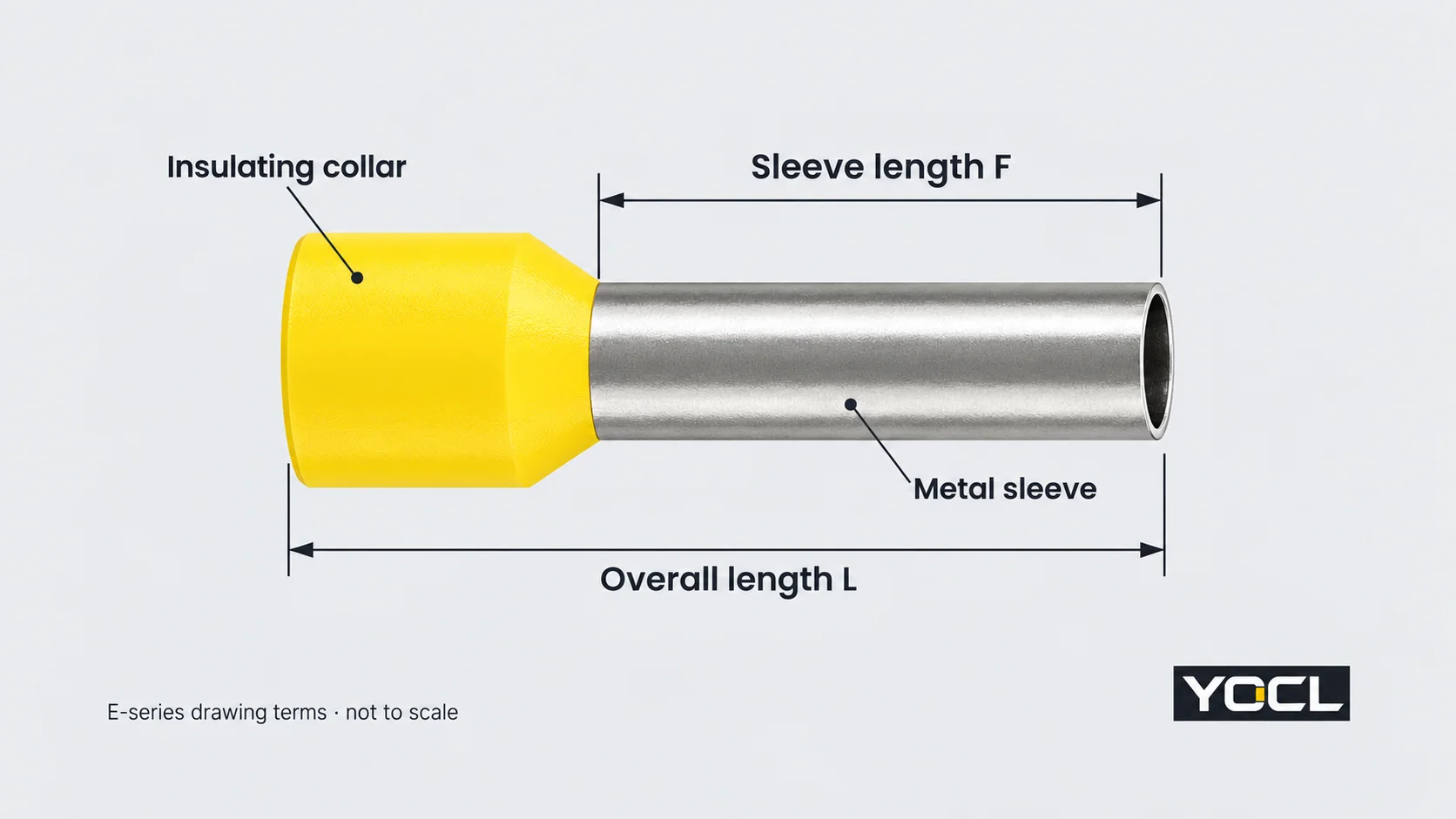
These are catalogue dimensions, not measurements of an installed connection. E1508 and E1512 accept the same declared conductor area but have different lengths. TE 1508 shares an 8 mm F dimension with E1508 while describing a different conductor arrangement. Neither area nor sleeve length alone determines terminal compatibility.
The receiving terminal’s insertion depth and preparation instructions determine which length is appropriate. Overall length cannot substitute for sleeve length when comparing the metal portion with the terminal’s contact space.
Twin notation and collar colour need their own reading
2 × 1.5 mm² means two conductors, each 1.5 mm². Their nominal areas add to 3 mm², but that arithmetic does not turn the twin ferrule into a single-wire 3 mm² model. Entry geometry, sleeve capacity, tooling and the permitted terminal arrangement remain separate requirements.
Colour is useful only within the specified catalogue coding. YOCL’s E-series lists colour options by size group. Its TE 7508 and TE 7510 models both declare 2 × 0.75 mm², yet list blue and grey collars respectively. Confirm the model and conductor designation rather than selecting a ferrule from colour alone.
What makes a ferrule compatible with a terminal?
Compatibility involves three interfaces:
- Conductor to ferrule: the conductor material, size and count must match the ferrule’s declared arrangement.
- Ferrule to crimping tool: the applicable tool and die must produce the required termination for that ferrule. Tool capacity alone does not establish the correct finished profile.
- Finished ferrule to terminal: the receiving device must permit the prepared conductor arrangement and accommodate its sleeve, crimp profile and collar.
“Screw terminal”, “spring terminal” and “push-in terminal” name connection mechanisms. They do not provide a universal answer to whether a ferrule is required, optional or unsuitable. Use the exact device’s instructions and any declared range for ferruled conductors. A ferrule that physically enters the opening has passed only a geometry check.
There is also an explicit scope boundary: UL 486F’s public scope excludes insulation-displacement connection (IDC) terminal blocks. Do not treat a prepared metal sleeve as a general replacement for the insulated wire that an IDC contact is designed to engage.
For a twin ferrule, verify acceptance of the two-conductor arrangement and its finished dimensions. A larger opening, a sufficient nominal area or a broad plastic collar cannot supply that authorization. Square and hexagonal crimp names also need to be checked against the actual ferrule, tooling and terminal documentation; neither is a universal compatibility rule.
What do standards and certification tell you?
Standard identity, product dimensions and connection approval answer different questions. DIN’s published title identifies a construction family; UL 486F’s public scope identifies its intended use and exclusions. A supplier’s reference to either standard is not, by itself, a model-specific certification record.
UL Solutions’ explanation of Component Recognition distinguishes a component’s assessment from certification of a complete end product. Recognized components have conditions of acceptability governing their use. Where certification is required, check the exact product record and applicable conditions alongside the receiving equipment’s documentation.
The YOCL dimensions above are first-party product declarations. They help interpret size fields; this article does not assert UL certification, a current rating or an approved terminal combination for those models.
Which document should you check next?
| Sorunuz | The next document to use |
|---|---|
| Which construction describes the part I need? | The single, bare or twin product-family information |
| What conductor does this model accept? | Its declared conductor size, material and count |
| What do its length and diameter fields mean? | The exact model/series drawing and dimension table |
| Which tool produces the required crimp? | The applicable ferrule and tooling instructions |
| Is the prepared end permitted in my terminal? | The exact receiving device’s wiring instructions and connection data |
| What evidence covers the intended equipment or market? | Relevant model certification records, conditions and equipment requirements |
Bu YOCL wire-ferrule catalogue routes these construction and dimension questions to the E, EN and TE product information. When asking for a model review, include the conductor size and count, required sleeve length and receiving terminal reference so the enquiry describes the complete interface.
Referanslar
- UL Standartlar ve Etkileşim — UL 486F: Bare and Covered Ferrules, Edition 3, 2024, revised August 2026. Official public scope, §§1.2, 1.6 and 1.8; function, conductor arrangement and exclusions.
- DIN Media — DIN 46228-4:2020-03: Tubular end-sleeves with plastic sleeve. Official publication identity and public introduction; the paid full standard was not consulted.
- YOCL ürün bilgileri — E Serisi Yalıtımlı Kablo Yüksükleri. Construction, model dimensions, drawing and declared colour options.
- YOCL ürün bilgileri — EN Yalıtımsız Kablo Ucu Yüksükleri. Bare flared-entry construction and dimension fields.
- YOCL ürün bilgileri — TE Çift Kablo Ucu Konnektörleri. Two-conductor notation, model dimensions and model-specific collar colours.
- UL Çözümleri — The UL Component Recognition Classification. Component conditions of acceptability and the end-product certification boundary.