
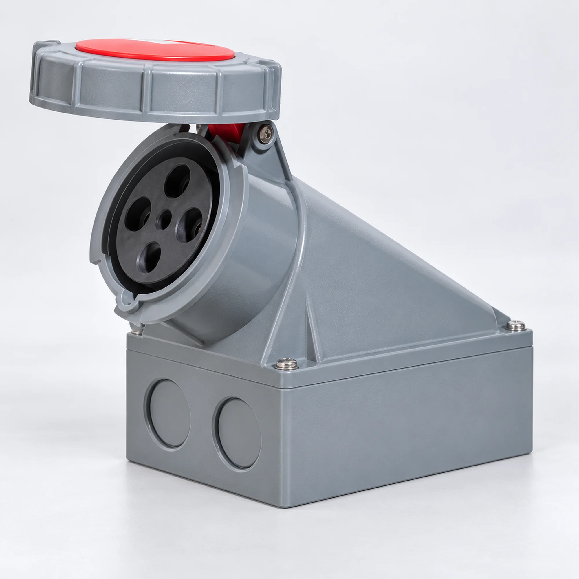
IP67 Aufputz-Industriesteckdosen
YOCL ELEKTRO IP67 Aufputz-Industriesteckdosen für feste industrielle Stromanschlüsse.
- Stromstärken: 16 / 32 / 63 / 125 A.
- Kontaktbelegung: 2P+E / 3P+E / 3P+N+E.
- Buchse mit Klappdeckel und Gehäuse für Rückwandmontage.
- Vollständige Modellauswahltabellen enthalten Spannung, Position des Schutzkontakts, Leiterquerschnitte und gehäusespezifische Abmessungen.
- Auswahl und Anfrage über vollständigen NM-Modellcode.
Übersicht
YOCL ELEKTRO IP67 Aufputz-Industriesteckdosen bieten einen festen weiblichen Anschlusspunkt für kompatible Industriestecker. Die Serie umfasst 16 / 32 / 63 / 125 A Nennströme und 2P+E, 3P+E, 3P+N+E Kontaktbelegungen. Jedes Modell kombiniert eine spezifische Stromstärke, Spannung, Erdungskontaktposition und Gehäusedesign.
Die Auswahltabellen fassen die verfügbaren Gehäuseversionen in einer Produktfamilie zusammen. Verwenden Sie den vollständigen NM-Modellcode, um die elektrische Konfiguration und die entsprechenden Einbaumaße anzugeben.
Merkmale
- Rückgehäuse und Aufputz-Befestigungsstruktur für eine feste Steckdoseninstallation.
- IP67 Schutzart für die aufgeführten Modelle.
- Klappdeckel an der Steckdosenfront.
- Blaue, rote und gelbe Konfigurationen, die in den Auswahltabellen nach exaktem Modell aufgeführt sind.
- Modellspezifische Leiterbereiche und Einbaumaße für die Auswahl des elektrischen Anschlusses und des Installationsraums.
- Alternative Erdungskontaktpositionen sind separat aufgeführt; passen Sie die Erdungsposition an die vorgesehene Steckerbelegung an.
Technische Daten
| Parameter | Spezifikation |
|---|---|
| Marke | YOCL ELEKTRO |
| Produkttyp | IP67 Aufputz-Industriesteckdosen |
| Kontaktgender | Buchse |
| Montage | Aufputzmontage |
| Schutzart | IP67 |
| Nennstromoptionen | 16 / 32 / 63 / 125 A |
| Kontaktbelegungen | 2P+E / 3P+E / 3P+N+E |
| Spannungskonfigurationen | 110–130 V; 220–240 V; 380–415 V; 220–380 / 240–415 V |
| Erdungskontaktpositionen | 4h / 6h / 3h |
| Leiterquerschnitt | Modellspezifische Werte in den Auswahltabellen |
| Gehäusevarianten | Ausführung 1 Gehäuse, 16/32 A; Ausführung 2 Gehäuse, 63/125 A; Ausführung 2 Gehäuse, 16/32 A; Standardgehäuse, 63/125 A; 3h Sonderkonfigurationen |
| Modelloptionen | 28 |
Modellauswahltabellen
Spannungs- und Stromwerte gehören zur exakten Modellzeile. Ein Bindestrich bedeutet, dass kein modellspezifischer Wert in den gelieferten Daten verfügbar ist.
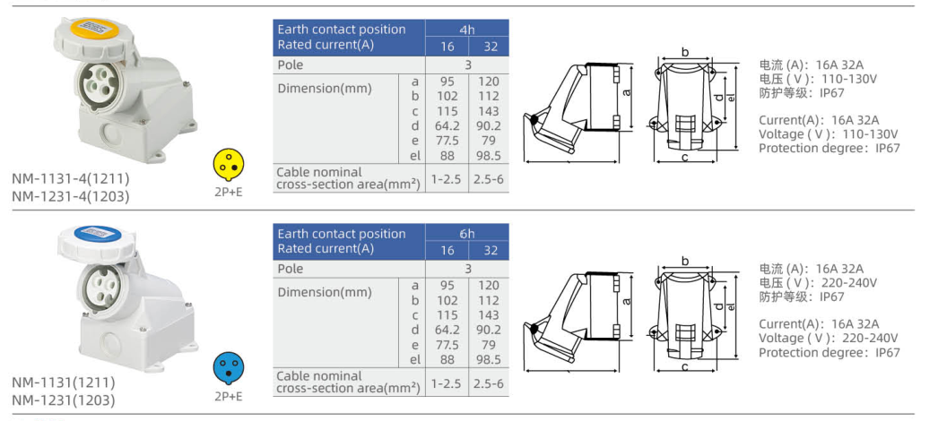
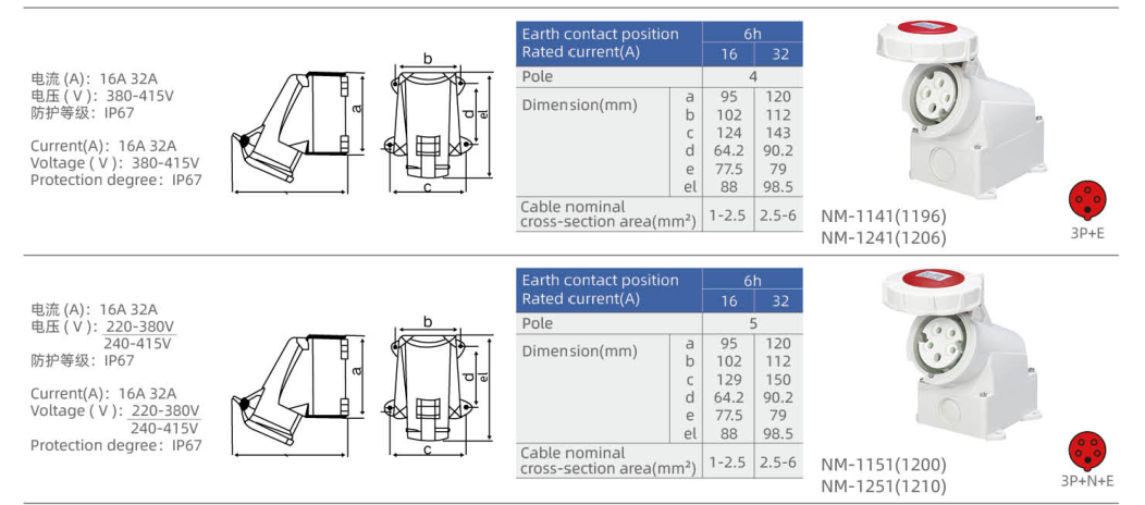
Ausführung 1 Gehäuse, 16/32 A
| Modell | Nennstrom (A) | Kontakte | Spannung (V) | Erdungsposition | Farbe | Conductor cross-section (mm²) |
|---|---|---|---|---|---|---|
| NM-1131-4 | 16 | 2P+E | 110–130 | 4h | Gelb | 1–2.5 |
| NM-1231-4 | 32 | 2P+E | 110–130 | 4h | Gelb | 2.5–6 |
| NM-1131 | 16 | 2P+E | 220–240 | 6h | Blau | 1–2.5 |
| NM-1231 | 32 | 2P+E | 220–240 | 6h | Blau | 2.5–6 |
| NM-1141 | 16 | 3P+E | 380–415 | 6h | Rot | 1–2.5 |
| NM-1241 | 32 | 3P+E | 380–415 | 6h | Rot | 2.5–6 |
| NM-1151 | 16 | 3P+N+E | 220–380 / 240–415 | 6h | Rot | 1–2.5 |
| NM-1251 | 32 | 3P+N+E | 220–380 / 240–415 | 6h | Rot | 2.5–6 |
Design 2 housing, 63/125 A
| Modell | Nennstrom (A) | Kontakte | Spannung (V) | Erdungsposition | Farbe | Conductor cross-section (mm²) |
|---|---|---|---|---|---|---|
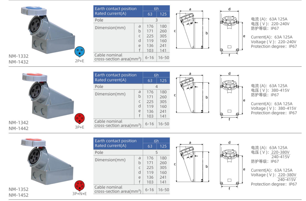
| NM-1332 | 63 | 2P+E | 220–240 | 6h | Blau | 6–16 |
| NM-1432 | 125 | 2P+E | 220–240 | 6h | Blau | 16–50 |
| NM-1342 | 63 | 3P+E | 380–415 | 6h | Rot | 6–16 |
| NM-1442 | 125 | 3P+E | 380–415 | 6h | Rot | 16–50 |
| NM-1352 | 63 | 3P+N+E | 220–380 / 240–415 | 6h | Rot | 6–16 |
| NM-1452 | 125 | 3P+N+E | 220–380 / 240–415 | 6h | Rot | 16–50 |
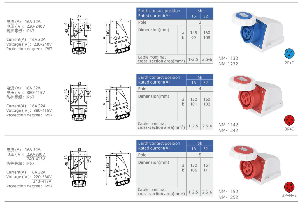
Design 2 housing, 16/32 A
| Modell | Nennstrom (A) | Kontakte | Spannung (V) | Erdungsposition | Farbe | Conductor cross-section (mm²) |
|---|---|---|---|---|---|---|
| NM-1132 | 16 | 2P+E | 220–240 | 6h | Blau | 1–2.5 |
| NM-1232 | 32 | 2P+E | 220–240 | 6h | Blau | 2.5–6 |
| NM-1142 | 16 | 3P+E | 380–415 | 6h | Rot | 1–2.5 |
| NM-1242 | 32 | 3P+E | 380–415 | 6h | Rot | 2.5–6 |
| NM-1152 | 16 | 3P+N+E | 220–380 / 240–415 | 6h | Rot | 1–2.5 |
| NM-1252 | 32 | 3P+N+E | 220–380 / 240–415 | 6h | Rot | 2.5–6 |
Standard housing, 63/125 A
| Modell | Nennstrom (A) | Kontakte | Spannung (V) | Erdungsposition | Farbe | Conductor cross-section (mm²) |
|---|---|---|---|---|---|---|
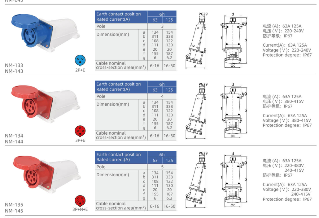
| NM-133 | 63 | 2P+E | 220–240 | 6h | Blau | 6–16 |
| NM-143 | 125 | 2P+E | 220–240 | 6h | Blau | 16–50 |
| NM-134 | 63 | 3P+E | 380–415 | 6h | Rot | 6–16 |
| NM-144 | 125 | 3P+E | 380–415 | 6h | Rot | 16–50 |
| NM-135 | 63 | 3P+N+E | 220–380 / 240–415 | 6h | Rot | 6–16 |
| NM-145 | 125 | 3P+N+E | 220–380 / 240–415 | 6h | Rot | 16–50 |
3h special configurations
| Modell | Nennstrom (A) | Kontakte | Spannung (V) | Erdungsposition | Farbe | Conductor cross-section (mm²) |
|---|---|---|---|---|---|---|
| NM-1142-3 | 16 | 3P+E | 380–415 | 3h | Rot | — |
| NM-1242-3 | 32 | 3P+E | 380–415 | 3h | Rot | — |
Abmessung
Dimension letters apply to the individual housing drawing. The same letter can identify a different feature on another housing version. Select the mounting dimensions from the exact model row.
Ausführung 1 Gehäuse, 16/32 A
| Modell | a (mm) | b (mm) | c (mm) | d (mm) | e (mm) | e1 (mm) |
|---|---|---|---|---|---|---|
| NM-1131-4 | 95 | 102 | 115 | 64.2 | 77.5 | 88 |
| NM-1231-4 | 120 | 112 | 143 | 90.2 | 79 | 98.5 |
| NM-1131 | 95 | 102 | 115 | 64.2 | 77.5 | 88 |
| NM-1231 | 120 | 112 | 143 | 90.2 | 79 | 98.5 |
| NM-1141 | 95 | 102 | 124 | 64.2 | 77.5 | 88 |
| NM-1241 | 120 | 112 | 143 | 90.2 | 79 | 98.5 |
| NM-1151 | 95 | 102 | 124 | 64.2 | 77.5 | 88 |
| NM-1251 | 120 | 112 | 150 | 90.2 | 79 | 98.5 |
Design 2 housing, 63/125 A
| Modell | a (mm) | b (mm) | c (mm) | d (mm) | e (mm) | f (mm) |
|---|---|---|---|---|---|---|
| NM-1332 | 176 | 171 | 225 | 119 | 136 | 103 |
| NM-1432 | 180 | 260 | 305 | 160 | 241 | 141 |
| NM-1342 | 176 | 171 | 225 | 119 | 136 | 103 |
| NM-1442 | 180 | 260 | 305 | 160 | 241 | 141 |
| NM-1352 | 176 | 171 | 225 | 119 | 136 | 103 |
| NM-1452 | 180 | 260 | 305 | 160 | 241 | 141 |
Design 2 housing, 16/32 A
| Modell | a (mm) | b (mm) |
|---|---|---|
| NM-1132 | 145 | 99 |
| NM-1232 | 160 | 108 |
| NM-1142 | 150 | 101 |
| NM-1242 | 160 | 108 |
| NM-1152 | 150 | 106 |
| NM-1252 | 161 | 111 |
Additional drawing dimensions (mm): Base width 82; fixing width 71; vertical spacings 16, 48 and 40; side drawing 103.
Standard housing, 63/125 A
| Modell | a (mm) | b (mm) | c (mm) | d (mm) | e (mm) | f (mm) | g (mm) |
|---|---|---|---|---|---|---|---|
| NM-133 | 134 | 311 | 108 | 111 | 20 | 155 | 6 |
| NM-143 | 154 | 338 | 122 | 130 | 20 | 187 | 6.2 |
| NM-134 | 134 | 311 | 108 | 111 | 20 | 155 | 6 |
| NM-144 | 154 | 338 | 122 | 130 | 20 | 187 | 6.2 |
| NM-135 | 134 | 311 | 108 | 111 | 20 | 155 | 6 |
| NM-145 | 154 | 338 | 122 | 130 | 20 | 187 | 6.2 |
Additional drawing dimensions (mm): Cable-entry drawing PG29.
Auswahlhilfe
- Choose the rated current and contact arrangement required for the connection.
- Match the voltage configuration and earth contact position to the mating plug. Colour alone is insufficient for model selection.
- Select the housing version and use its own mounting and conductor-range values.
- Include the complete model code and quantity in the enquiry.
Bestellinformationen
For a quotation, provide the complete NM model code, required quantity and mounting version. If identifying a replacement, include a photograph of the existing contact face and mounting layout.