
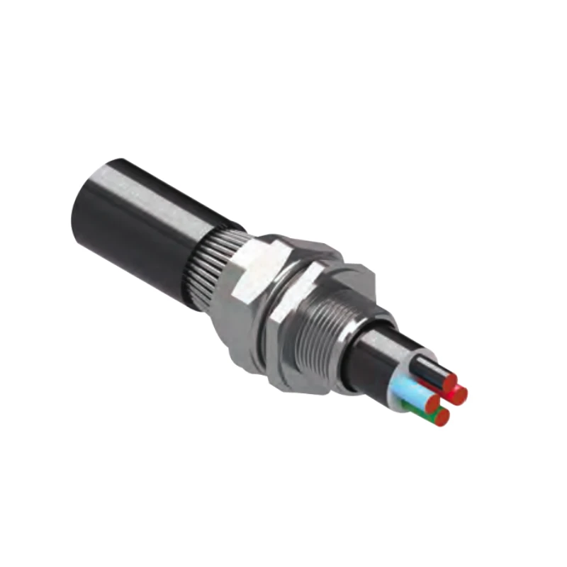
BWC Kabelverschraubung
YOCL ELECTRIC BWC Kabelverschraubungen bieten mechanischen Halt für Panzerwelle in trockenen Inneninstallationen. Der Katalog listet 13 Modelle von VO-BWC001 bis VO-BWC013 mit metrischen und NPT-Einführungsgewindereferenzen.
- Messingkonstruktion mit vernickelter Option.
- IP2X IP-Schutzart ohne Haube angegeben.
- Modellspezifische Kabel-, Panzer-, Sechskant- und Installationsdrehmomentwerte sind unten aufgeführt.
Übersicht
YOCL ELECTRIC BWC Kabelverschraubungen sind Kabelverschraubungen für Stahlbandbewehrte Kabel (SWA) in trockenen Inneninstallationen. Der Katalog beschreibt einen Messingkörper mit oder ohne Vernickelung und mechanischen Halt der Kabelbewehrung. Dreizehn Modelle werden mit metrischen und NPT-Gewindereferenzen aufgeführt.
Merkmale
- Bewehrungshalt: Die Baugruppe ist so konzipiert, dass sie gepanzerte Kabel am Geräteeingang greift.
- Messingkörper-Optionen: Messing blank oder vernickelt, wie im Katalog beschrieben.
- IP2X ohne Hülse: die angegebene Schutzart für die BWC-Verschraubung ohne die optionale Hülse.
- Modellspezifisches Anzugsdrehmoment: Die Drehmomentwerte werden für die aufgeführten Modelle angegeben.
Technische Daten
| Parameter | Spezifikation |
|---|---|
| Produktserien | BWC |
| Kabeltyp | Stahlbandbewehrt (SWA) |
| Gehäusematerial | Messing; vernickelte Messingoption |
| Schutzart | IP2X ohne Hülse |
| Bestimmungsumgebung | Trocken, Innenbereich |
| Gewindeangaben in Spalten | Metrisch und NPT |
| Bezugsnorm | BS 6121, wie im Katalog angegeben |
| Aufgeführte Modelle | 13 |
Abmessung
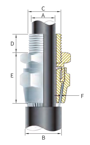
Die Tabelle gibt die Quellabmessungen und das Installationsdrehmoment nach Modell wieder. A und B sind separate Katalog-Kabelmaße; bestätigen Sie deren Messpunkte am Kabel, bevor Sie eine Verschraubung auswählen. Die Spalte NPT listet Alternativen auf, wo geliefert. Ein Bindestrich bedeutet, dass die Quelle keinen Wert angibt. Alle Maßangaben sind Millimeter; Drehmoment ist N·m.
| Modell | Größe | Metrisches Gewinde C | Metrisch min D | NPT C | NPT min D | Kabel max A | Kabel min B | Kabel max B | Max. Länge E | Min. Panzerung F | Max. Panzerung F | Max. Schlüsselweite | Max. Ecken über Ecken | Drehmoment (N·m) |
|---|---|---|---|---|---|---|---|---|---|---|---|---|---|---|
| VO-BWC001 | 0-20S | M20×1.5 | 10 | 1/2 oder 3/4 | 15 | 12.0 | 11.5 | 16.0 | 23.0 | 0.90 | 1.25 | 22 | 25 | 35.0 |
| VO-BWC002 | 1-20 | M20×1.5 | 10 | 1/2 oder 3/4 | 15 | 15.0 | 14.5 | 20.5 | 26.0 | 0.90 | 1.25 | 25/27 | 28/30 | 35.0 |
| VO-BWC003 | 2-25 | M25×1.5 | 10 | 1/2 oder 1 | 15/19 | 20.0 | 20.5 | 26.5 | 29.0 | 1.25 | 1.60 | 35 | 39 | 50.0 |
| VO-BWC004 | 3-32 | M32×1.5 | 10 | 1 or 1¼ | 19 | 26.5 | 26.5 | 33.5 | 32.0 | 1.60 | 2.00 | 42 | 47 | 70.0 |
| VO-BWC005 | 4-40 | M40×1.5 | 15 | 1¼ or 1½ | 19/21 | 34.0 | 33.0 | 42.5 | 36.0 | 1.60 | 5.00 | 52 | 59 | 90.0 |
| VO-BWC006 | 5-50 | M50×1.5 | 15 | 1½ or 2 | 21 | 44.5 | 42.5 | 52.5 | 45.0 | 2.00 | 2.50 | 65 | 73 | 100.0 |
| VO-BWC007 | 6-63 | M63×1.5 | 15 | 2 or 2½ | 21/30 | 56.5 | 52.5 | 65.5 | 50.0 | 2.00 | 2.50 | 80 | 90 | 120.0 |
| VO-BWC008 | 7-75 | M75×1.5 | 15 | 2½ or 3 | 30/32 | 67.5 | 65.5 | 78.0 | 60.0 | 2.50 | 3.15 | 96 | 108 | 120.0 |
| VO-BWC009 | 8-80 | M80×2.0 | 20 | 3 | 32 | 74.0 | 78.0 | 82.0 | 65.0 | 2.50 | 3.15 | 96 | 108 | 120.0 |
| VO-BWC010 | 9-90 | M90×2.0 | 20 | 3 or 3½ | 32/33 | 81.5 | 82.0 | 91.0 | 69.0 | 3.00 | 3.50 | 111 | 125 | 120.0 |
| VO-BWC011 | 10-100 | M100×2.0 | 20 | 3½ or 4 | 33/34 | 91.0 | 90.0 | 100.0 | 88.0 | 3.00 | 3.50 | — | — | 120.0 |
| VO-BWC012 | 11-110 | M110×2.0 | 20 | 4 | 34 | 98.0 | 100.0 | 114.0 | 88.0 | 3.00 | 4.00 | — | — | 120.0 |
| VO-BWC013 | 12-120 | M120×2.0 | 20 | — | — | 103.0 | 103.0 | 118.0 | 100.0 | 3.00 | 4.00 | — | — | 120.0 |
Auswahlhilfe
Match the entry thread to the equipment, then check the cable’s inner and outer sheath dimensions and armour thickness against the A, B and F values. Confirm available thread engagement, maximum installed length and tool clearance before specifying the model.
Installationshinweise
The supplied assembly sequence is summarized below. Use the model-specific torque in the table for the outer-to-inner gland connection.
- Measure the cable’s inner and outer sheaths with a dimension tape.
- Cut back the outer sheath to expose the armour, keeping the exposed length no longer than the outer component.
- Remove the locknut, then slide the shroud and outer component over the cable.
- Pass the cable end through the inner component and splay the armour wires over the cone.
- Tighten the outer component onto the inner component to the listed installation torque using a spanner.
- Insert the gland bush into the equipment cable entry, tighten the locknut, then slide the shroud over the gland.
Bestellinformationen
Provide the full BWC model code, cable and armour dimensions, thread form, required finish and quantity when requesting a quotation.