
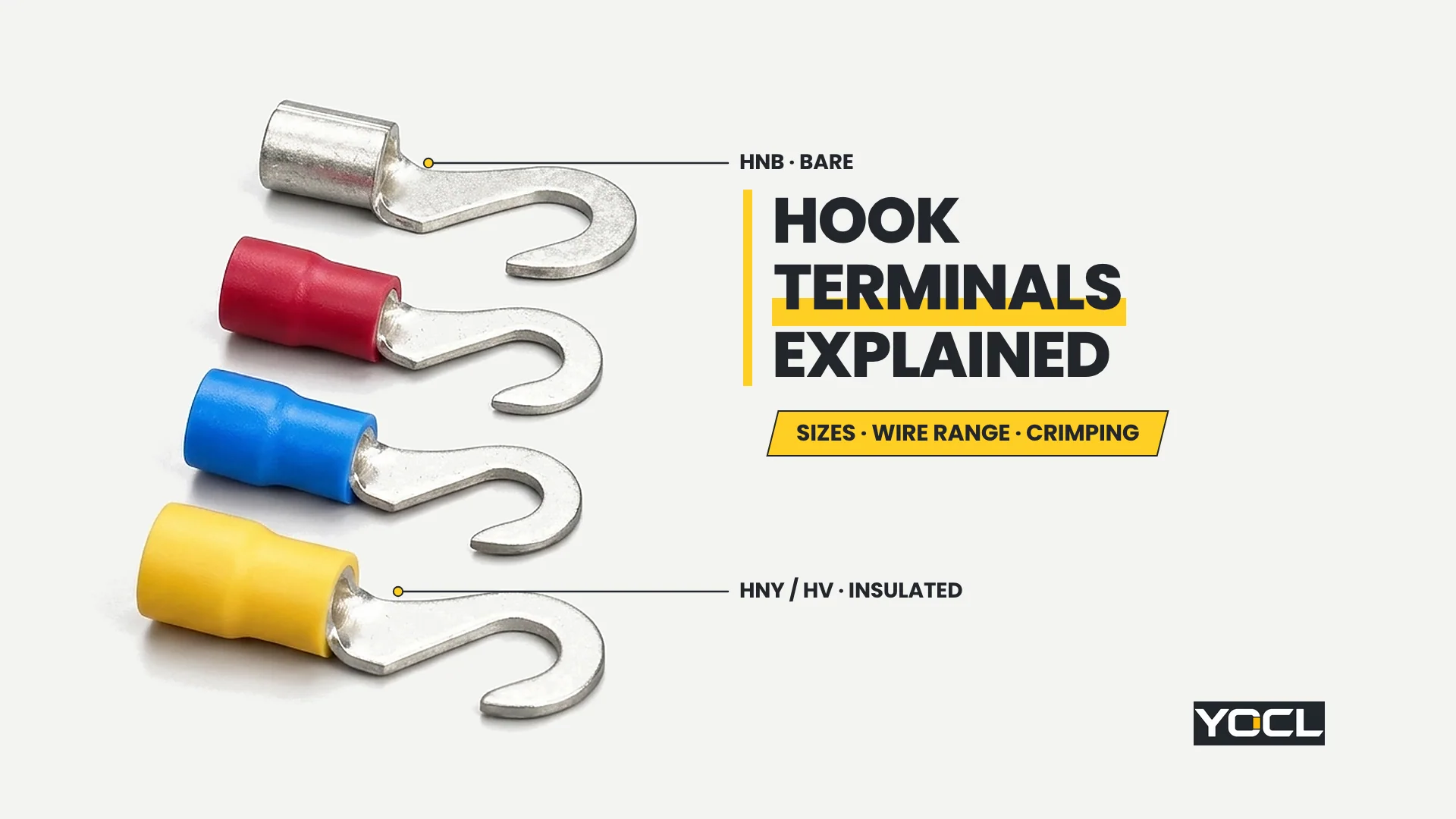
Terminales de gancho son conectores de crimpado por compresión en frío cuya pala de contacto forma una curva en C de entrada lateral abierta en lugar de un anillo cerrado o una horquilla de dos puntas, lo que permite que el terminal se deslice lateralmente sobre un perno o espárrago aflojado y se bloquee bajo la cabeza del tornillo al apretarlo. En los modelos 65 de YOCL ELECTRIC, tres grupos de cables se combinan con cinco aberturas para pernos.
Los ingenieros especifican una pala de gancho para un problema de instalación práctico: un punto de conexión atornillado donde el tornillo puede aflojarse unas cuantas vueltas para trabajos de cableado o modernización, pero no puede (o no debe) retirarse por completo. Un terminal de anillo cerrado no puede instalarse sin quitar el tornillo por completo, mientras que un gancho en C abierto se desliza sobre el vástago desde el lateral en filas de terminales abarrotadas o bloques de tornillos cautivos. Para mantener distintos los temas relacionados, la estructura general de los terminales de crimpado pertenece a qué es un terminal de crimpado, la elección entre anillos cerrados y horquillas de dos puntas pertenece a terminales de anillo frente a terminales de horquilla, y las propiedades del material aislante pertenecen a PVC frente a terminales de crimpado de nailon o no aislados.
Geometría de gancho abierto vs anillos cerrados: El compromiso de entrada lateral
Una hoja de gancho abierto combina el acceso de instalación de entrada lateral con un envolvimiento parcial alrededor del eje del tornillo, situándose mecánicamente entre un anillo cerrado y un tenedor recto. Sin embargo, la misma garganta lateral que permite que el gancho se deslice sobre un perno aflojado también permite que se deslice lateralmente si el sujetador se afloja.
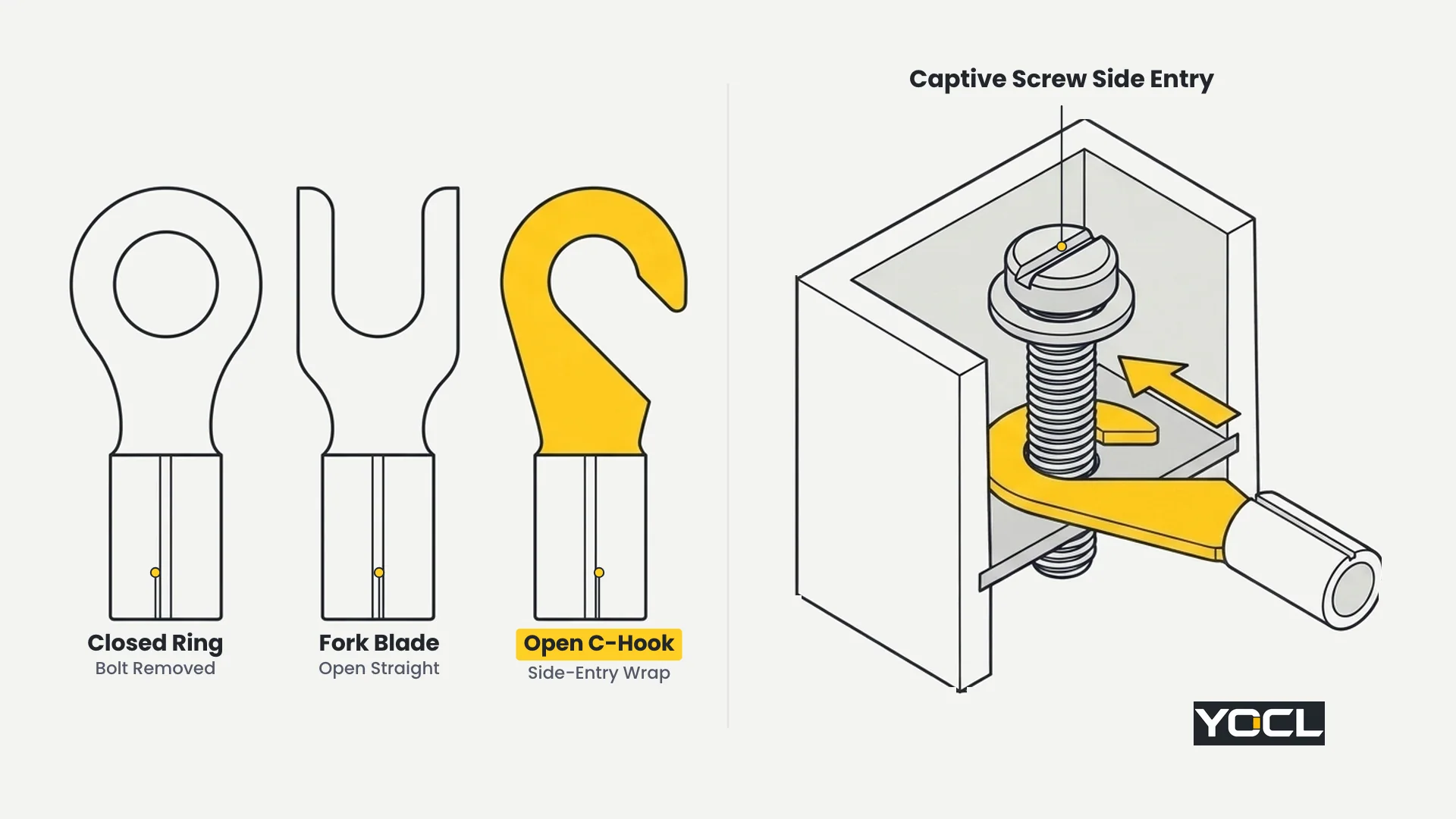
Trata esa garganta abierta como una consecuencia geométrica directa en lugar de una calificación de rendimiento oculta:
- Por qué el gancho en C ayuda durante el servicio: Porque la punta curva se engancha en la parte posterior del perno una vez asentada, tirar recto hacia atrás a lo largo del eje del cable hace que la curva interna se ajuste contra el vástago del tornillo en lugar de deslizarse directamente hacia afuera como un tenedor paralelo.
- Por qué no es una unión cautiva: Si el ciclo térmico o un apriete inadecuado dejan la cabeza del tornillo suelta, el movimiento lateral hacia la garganta abierta puede desenganchar completamente la cuchilla, algo que un anillo cerrado previene físicamente siempre que el perno permanezca en su lugar.
- Regla de selección de campo: Especificar un anillo cerrado siempre que el perno pueda ser retirado y el cable deba permanecer cautivo en el espárrago; especificar un terminal de gancho donde el hardware cautivo o el acceso ajustado al panel exijan entrada lateral y la firmeza del apriete del tornillo se verifique durante el ensamblaje.
Sistema de Tamaño de Terminales de Gancho: Códigos de Modelo, Aberturas para Perno y Tablas Completas
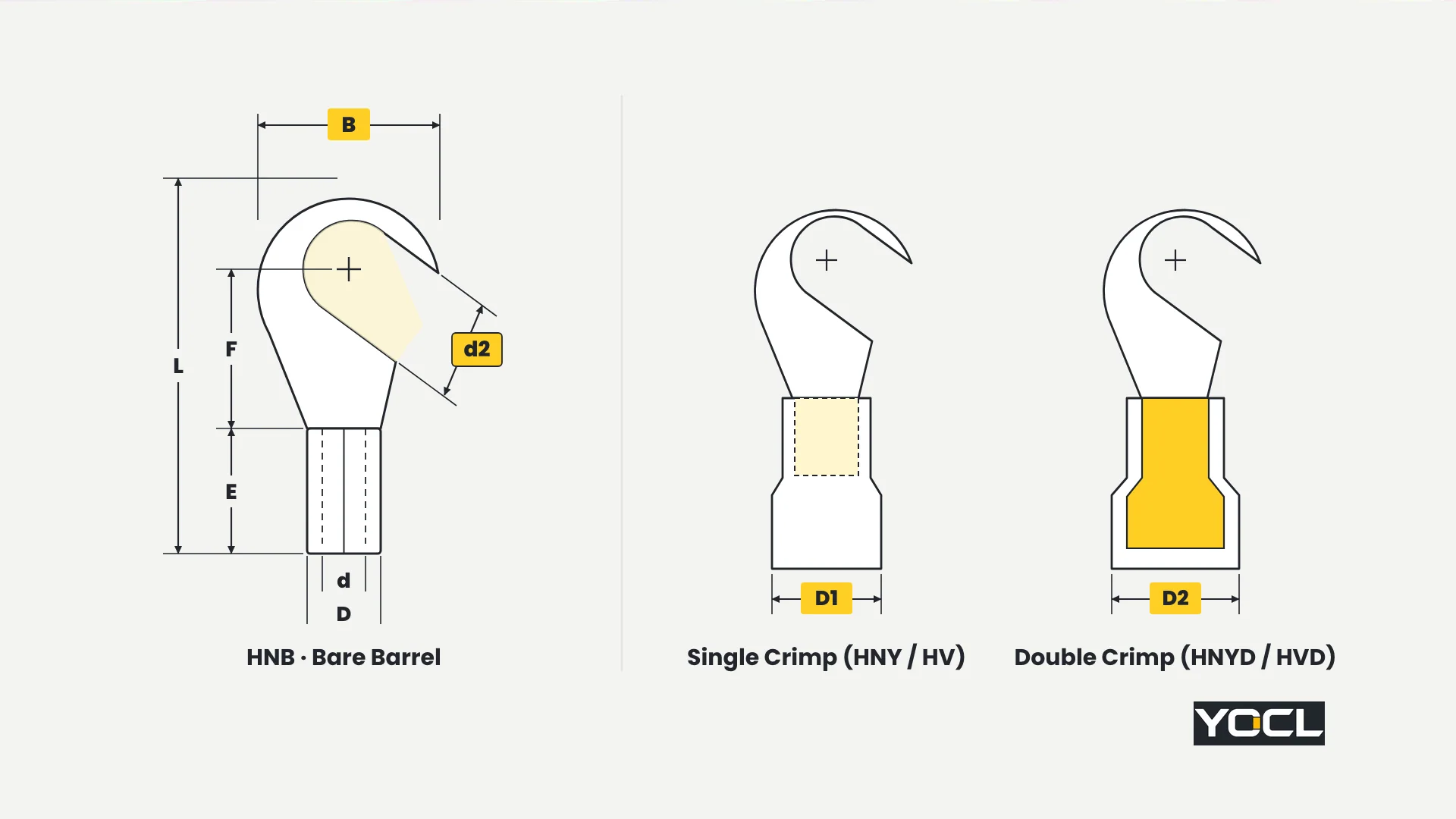
Seleccionando terminales de gancho comienza con precisión decodificando el sistema de código de modelo compartido de YOCL y la escalera dimensional de tres grupos a través de todos los SKU del catálogo 65. Cada código de modelo empareja un prefijo de rango de conductor con un sufijo de tamaño de perno nominal—y el sufijo nominal después del guion nunca es igual a la apertura de gancho medida d2.
Decodificación de la escalera compartida de conductores y pernos
Las tres familias YOCL—cobre desnudo HNB, aislado de nailon HNY/HNYD, y aislado de PVC HV/HVD—utiliza la misma sintaxis de código de modelo: [Serie] [Grupo]-[Código de Tornillo]. Por ejemplo, HNB 2-5 identifica la serie HNB, grupo de conductores 2 (1.5–2.5 mm²), y código de tornillo 5 (#10 tornillo).
- Tres grupos de conductores compartidos: Grupo 1.25 cubiertas 0.5–1.5 mm²; Grupo 2 cubiertas 1.5–2.5 mm²; Grupo 5.5 cubiertas 4–6 mm². Las páginas de HNY/HNYD y HV/HVD aisladas también imprimen los equivalentes AWG 22–16, AWG 16–14, y AWG 12–10 rangos y codifican por colores los manguitos Rojo (1.25), Azul (2), and Amarillo (5.5), whereas the HNB page lists mm² only. Copper contact thickness across all three families is 0.7 mm (group 1.25), 0.8 mm (group 2), and 1.0 mm (group 5.5).
- Catalogue Imax label boundary: Across all three families, the group tables list Imax = 19 A (group 1.25), 27 A (group 2), and 48 A (group 5.5). As stated on YOCL’s product pages, Imax is the catalogue’s maximum-current label for the conductor group and test or installation conditions are not provided—never treat Imax as an installed circuit ampacity.
- Nominal bolt code vs actual opening d2: Each family lists 13 models per crimp style (4 in group 1.25, 4 in group 2, and 5 in group 5.5, where the 5/16 bolt size exists only in group 5.5). The number after the dash (3.5, 4, 5, 6, 8) is the nominal screw code, while d2 is the actual clearance opening in millimeters:
- Suffix -3.5 (#6 US bolt) → actual opening d2 = 3.7 mm
- Suffix -4 (#8 US bolt) → actual opening d2 = 4.3 mm
- Suffix -5 (#10 US bolt) → actual opening d2 = 5.3 mm
- Suffix -6 (1/4 US bolt) → actual opening d2 = 6.5 mm
- Suffix -8 (5/16 US bolt, group 5.5 only) → actual opening d2 = 8.5 mm
- Secuencia de selección: Match wire cross-section to the conductor group first, match the stud or screw size to d2 second, and check B (outer hook width), F (barrel top to bolt center), and L (overall length) against the barrier walls around the terminal post—because a hook slides on from the side, it requires lateral clearance beside the screw. (For tab-style disconnects that use a different sizing system, see the quick-disconnect terminal size chart.)
Family 1: HNB Non-Insulated Hook Terminals (TO Type)
de YOCL HNB non-insulated hook terminals (TO type) are uninsulated copper terminals across 13 models, providing the shortest overall length L (15.7–27.0 mm) and bare barrels for direct visual inspection or post-crimp heat-shrink tubing.
Within each conductor group, copper thickness, barrel length E, barrel outer diameter D, and barrel inner diameter d are shared: Group 1.25 (0.5–1.5 mm², Imax 19 A without test/installation conditions stated) has thickness 0.7 mm, E = 4.8 mm, D = 3.4 mm, d = 1.7 mm; Grupo 2 (1.5–2.5 mm², Imax 27 A, no conditions stated) has thickness 0.8 mm, E = 4.8 mm, D = 4.1 mm, d = 2.3 mm; Grupo 5.5 (4–6 mm², Imax 48 A, no conditions stated) has thickness 1.0 mm, E = 6.0 mm, D = 5.6 mm, d = 3.4 mm.
| Modelo | Section (mm²) | Bolt | d2 (mm) | B (mm) | F (mm) | L (mm) | E (mm) | D (mm) | d (mm) |
|---|---|---|---|---|---|---|---|---|---|
| HNB 1.25-3.5 | 0.5–1.5 | #6 | 3.7 | 8.0 | 7.0 | 15.8 | 4.8 | 3.4 | 1.7 |
| HNB 1.25-4 | 0.5–1.5 | #8 | 4.3 | 8.0 | 7.0 | 15.8 | 4.8 | 3.4 | 1.7 |
| HNB 1.25-5 | 0.5–1.5 | #10 | 5.3 | 8.0 | 7.0 | 15.8 | 4.8 | 3.4 | 1.7 |
| HNB 1.25-6 | 0.5–1.5 | 1/4 | 6.5 | 11.6 | 11.0 | 21.8 | 4.8 | 3.4 | 1.7 |
| HNB 2-3.5 | 1.5–2.5 | #6 | 3.7 | 8.5 | 7.4 | 16.8 | 4.8 | 4.1 | 2.3 |
| HNB 2-4 | 1.5–2.5 | #8 | 4.3 | 8.5 | 7.4 | 16.8 | 4.8 | 4.1 | 2.3 |
| HNB 2-5 | 1.5–2.5 | #10 | 5.3 | 9.5 | 7.3 | 16.8 | 4.8 | 4.1 | 2.3 |
| HNB 2-6 | 1.5–2.5 | 1/4 | 6.5 | 12.0 | 11.0 | 21.8 | 4.8 | 4.1 | 2.3 |
| HNB 5.5-3.5 | 4–6 | #6 | 3.7 | 7.2 | 6.1 | 15.7 | 6.0 | 5.6 | 3.4 |
| HNB 5.5-4 | 4–6 | #8 | 4.3 | 9.5 | 9.5 | 19.8 | 6.0 | 5.6 | 3.4 |
| HNB 5.5-5 | 4–6 | #10 | 5.3 | 9.5 | 9.5 | 19.8 | 6.0 | 5.6 | 3.4 |
| HNB 5.5-6 | 4–6 | 1/4 | 6.5 | 12.0 | 10.3 | 22.5 | 6.0 | 5.6 | 3.4 |
| HNB 5.5-8 | 4–6 | 5/16 | 8.5 | 15.0 | 13.5 | 27.0 | 6.0 | 5.6 | 3.4 |
Regla de selección: Choose HNB bare copper models when minimal overall length L (15.7–27.0 mm) is required in tight spaces or when external heat-shrink tubing will be applied after crimping; switch to HNY/HNYD or HV/HVD whenever pre-insulated color-coded barrels are required.
Family 2: HNY (Single Crimp) and HNYD (Double Crimp) Nylon Hook Terminals
de YOCL HNY/HNYD nylon hook terminals pair a copper contact with a nylon insulating sleeve across 13 matched single-crimp (HNY) and double-crimp (HNYD) rows (26 models). For this nylon family—and this family only—the product page states 600 V y 105 °C across all three size groups.
Group parameters pair Rojo (group 1.25: 0.5–1.5 mm² / AWG 22–16, thickness 0.7 mm, catalogue Imax 19 A without test/installation conditions), Azul (group 2: 1.5–2.5 mm² / AWG 16–14, thickness 0.8 mm, Imax 27 A, no conditions stated), and Amarillo (group 5.5: 4–6 mm² / AWG 12–10, thickness 1.0 mm, Imax 48 A, no conditions stated).
| HNY (Single) | HNYD (Double) | Color | Bolt | d2 (mm) | B (mm) | F (mm) | L (mm) | E (mm) | D1 (mm) | D2 (mm) |
|---|---|---|---|---|---|---|---|---|---|---|
| HNY 1.25-3.5 | HNYD 1.25-3.5 | Rojo | #6 | 3.7 | 8.0 | 7.0 | 22.0 | 11.0 | 4.3 | 4.8 |
| HNY 1.25-4 | HNYD 1.25-4 | Rojo | #8 | 4.3 | 8.0 | 7.0 | 22.0 | 11.0 | 4.3 | 4.8 |
| HNY 1.25-5 | HNYD 1.25-5 | Rojo | #10 | 5.3 | 8.0 | 7.0 | 22.0 | 11.0 | 4.3 | 4.8 |
| HNY 1.25-6 | HNYD 1.25-6 | Rojo | 1/4 | 6.5 | 11.6 | 11.0 | 28.0 | 11.0 | 4.3 | 4.8 |
| HNY 2-3.5 | HNYD 2-3.5 | Azul | #6 | 3.7 | 8.5 | 7.4 | 23.0 | 11.0 | 4.9 | 5.2 |
| HNY 2-4 | HNYD 2-4 | Azul | #8 | 4.3 | 8.5 | 7.4 | 23.0 | 11.0 | 4.9 | 5.2 |
| HNY 2-5 | HNYD 2-5 | Azul | #10 | 5.3 | 9.5 | 7.3 | 23.0 | 11.0 | 4.9 | 5.2 |
| HNY 2-6 | HNYD 2-6 | Azul | 1/4 | 6.5 | 12.0 | 11.0 | 28.0 | 11.0 | 4.9 | 5.2 |
| HNY 5.5-3.5 | HNYD 5.5-3.5 | Amarillo | #6 | 3.7 | 7.2 | 6.1 | 23.7 | 14.0 | 6.9 | 7.2 |
| HNY 5.5-4 | HNYD 5.5-4 | Amarillo | #8 | 4.3 | 9.5 | 9.5 | 27.8 | 14.0 | 6.9 | 7.2 |
| HNY 5.5-5 | HNYD 5.5-5 | Amarillo | #10 | 5.3 | 9.5 | 9.5 | 27.8 | 14.0 | 6.9 | 7.2 |
| HNY 5.5-6 | HNYD 5.5-6 | Amarillo | 1/4 | 6.5 | 12.0 | 10.3 | 30.5 | 14.0 | 6.9 | 7.2 |
| HNY 5.5-8 | HNYD 5.5-8 | Amarillo | 5/16 | 8.5 | 15.0 | 13.5 | 35.0 | 14.0 | 6.9 | 7.2 |
Regla de selección: Choose HNY/HNYD when the specification requires nylon insulation with stated 600 V and 105 °C group parameters; select HNYD (D2 = 4.8 / 5.2 / 7.2 mm) over HNY (D1 = 4.3 / 4.9 / 6.9 mm) when a double-crimp barrel over the wire insulation is needed.
Family 3: HV (Single Crimp) and HVD (Double Crimp) PVC Pre-Insulated Hook Terminals
de YOCL HV/HVD pre-insulated hook terminals pair a copper contact with a PVC sleeve across 13 matched pairs (26 models), where HVD incorporates an additional copper tube with sleeve described on the source page as double pressure.
Group wire ranges (Rojo 0.5–1.5 mm² / AWG 22–16; Azul 1.5–2.5 mm² / AWG 16–14; Amarillo 4–6 mm² / AWG 12–10), copper thicknesses (0.7 / 0.8 / 1.0 mm), and catalogue Imax labels (19 A / 27 A / 48 A, without test or installation conditions stated) match the shared ladder, while the HV/HVD page states que no hay voltage or temperature rating.
| HV (Single) | HVD (Double) | Color | Bolt | d2 (mm) | B (mm) | F (mm) | L (mm) | E (mm) | D1 (mm) | D2 (mm) |
|---|---|---|---|---|---|---|---|---|---|---|
| HV 1.25-3.5 | HVD 1.25-3.5 | Rojo | #6 | 3.7 | 8.0 | 7.0 | 21.0 | 10.0 | 4.3 | 4.5 |
| HV 1.25-4 | HVD 1.25-4 | Rojo | #8 | 4.3 | 8.0 | 7.0 | 21.0 | 10.0 | 4.3 | 4.5 |
| HV 1.25-5 | HVD 1.25-5 | Rojo | #10 | 5.3 | 8.0 | 7.0 | 21.0 | 10.0 | 4.3 | 4.5 |
| HV 1.25-6 | HVD 1.25-6 | Rojo | 1/4 | 6.5 | 11.6 | 11.0 | 27.0 | 10.0 | 4.3 | 4.5 |
| HV 2-3.5 | HVD 2-3.5 | Azul | #6 | 3.7 | 8.5 | 7.4 | 22.0 | 10.0 | 4.9 | 5.2 |
| HV 2-4 | HVD 2-4 | Azul | #8 | 4.3 | 8.5 | 7.4 | 22.0 | 10.0 | 4.9 | 5.2 |
| HV 2-5 | HVD 2-5 | Azul | #10 | 5.3 | 9.5 | 7.3 | 22.0 | 10.0 | 4.9 | 5.2 |
| HV 2-6 | HVD 2-6 | Azul | 1/4 | 6.5 | 12.0 | 11.0 | 27.0 | 10.0 | 4.9 | 5.2 |
| HV 5.5-3.5 | HVD 5.5-3.5 | Amarillo | #6 | 3.7 | 7.2 | 6.1 | 22.7 | 13.0 | 6.7 | 7.0 |
| HV 5.5-4 | HVD 5.5-4 | Amarillo | #8 | 4.3 | 9.5 | 9.5 | 26.8 | 13.0 | 6.7 | 7.0 |
| HV 5.5-5 | HVD 5.5-5 | Amarillo | #10 | 5.3 | 9.5 | 9.5 | 26.8 | 13.0 | 6.7 | 7.0 |
| HV 5.5-6 | HVD 5.5-6 | Amarillo | 1/4 | 6.5 | 12.0 | 10.3 | 29.5 | 13.0 | 6.7 | 7.0 |
| HV 5.5-8 | HVD 5.5-8 | Amarillo | 5/16 | 8.5 | 15.0 | 13.5 | 34.0 | 13.0 | 6.7 | 7.0 |
Regla de selección: Choose HV (single crimp, D1 = 4.3 / 4.9 / 6.7 mm) or HVD (double-pressure copper tube + PVC sleeve, D2 = 4.5 / 5.2 / 7.0 mm) when standard PVC pre-insulated hook terminals with 1.0 mm shorter sleeve lengths E (10.0 / 10.0 / 13.0 mm) and overall lengths L (21.0–34.0 mm) fit the panel layout.
Three Hook-Terminal Families on One Shared Dimensional Ladder
Comparing HNB, HNY/HNYD, and HV/HVD side by side shows that all 65 models share one identical contact-blade ladder—every matching suffix has the exact same d2 opening, outer hook width B, neck length F, and copper thickness. Only the barrel insulation, sleeve length E, and overall length L change.
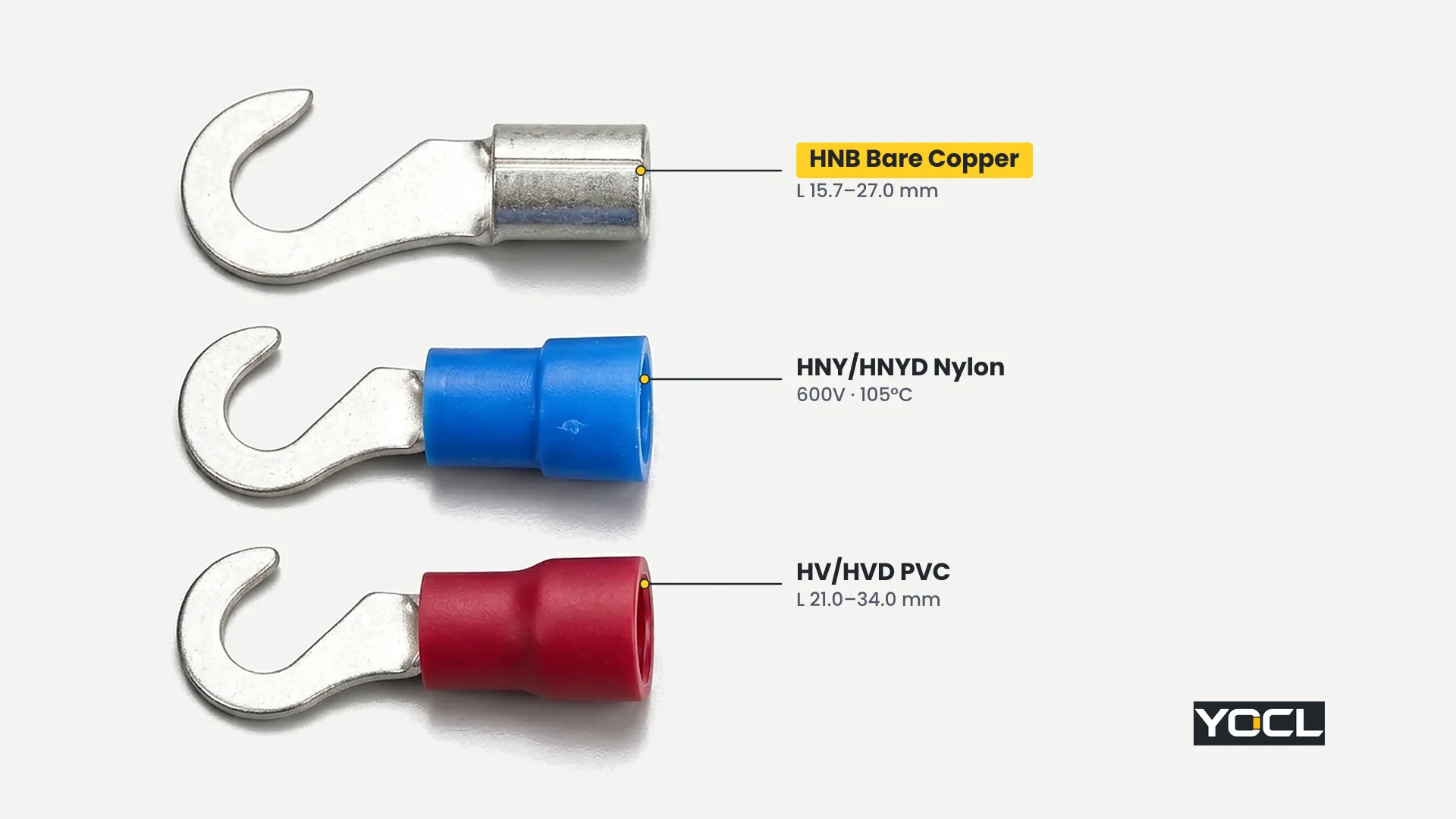
Because the hook blade itself never changes between families for a given model suffix, switching between bare, nylon, and PVC versions affects only the wire-entry barrel:
- HNB (TO type): Uninsulated copper barrel with E = 4.8 / 4.8 / 6.0 mm and the shortest overall lengths (L = 15.7–27.0 mm).
- HNY and HNYD: Nylon-insulated single-crimp and double-crimp barrels with E = 11.0 / 11.0 / 14.0 mm, L = 22.0–35.0 mm, and stated 600 V / 105 °C group ratings.
- HV and HVD: PVC pre-insulated single-crimp and double-pressure barrels with E = 10.0 / 10.0 / 13.0 mm y L = 21.0–34.0 mm (each 1.0 mm shorter in E and L than the corresponding HNY/HNYD row). For how PVC, nylon, and non-insulated sleeves compare in application, see PVC frente a terminales de crimpado de nailon o no aislados.
Single Crimp vs Double Crimp Barrels: D1, D2, and Die Matching
In both insulated families, the single-crimp versions (HNY, HV) and double-crimp versions (HNYD, HVD) differ in barrel construction and outer entry diameter: every double-crimp model carries a larger barrel diameter D2 > D1, providing a second compression zone over the wire insulation alongside the conductor crimp.
Look at how the published barrel diameters step up from D1 (single crimp) to D2 (double crimp) across all three wire groups:
- Group 1.25 (Red, 0.5–1.5 mm²): HNY D1 = 4.3 mm vs HNYD D2 = 4.8 mm; HV D1 = 4.3 mm vs HVD D2 = 4.5 mm.
- Group 2 (Blue, 1.5–2.5 mm²): HNY D1 = 4.9 mm vs HNYD D2 = 5.2 mm; HV D1 = 4.9 mm vs HVD D2 = 5.2 mm.
- Group 5.5 (Yellow, 4–6 mm²): HNY D1 = 6.9 mm vs HNYD D2 = 7.2 mm; HV D1 = 6.7 mm vs HVD D2 = 7.0 mm.
As the HV/HVD specification page notes, the HVD double-crimp barrel contains an additional internal copper tube inside the sleeve—referred to as a double-pressure construction—so closing the crimping tool compresses the primary copper barrel onto the stripped conductor strands while the rear section grips the wire insulation jacket. Match the crimping die cavity strictly to the chosen construction (D1 vs D2): crimping a larger D2 double-crimp barrel in a narrow single-crimp die setting crushes the sleeve unevenly and damages the insulation entry.
Preguntas frecuentes
Should I choose a hook terminal or a ring terminal?
Access to the fastener decides. Choose a closed ring terminal whenever the screw or nut can be removed completely and the wire must remain captive on the stud. Choose a hook terminal when captive hardware or tight spacing allows loosening the screw only a few turns and clamp tightness is verified; see terminales de anillo frente a terminales de horquilla.
What does the number after the dash mean in a hook terminal code?
The number after the dash (3.5, 4, 5, 6, o 8) is the nominal screw code, not the measured hook opening. Always read the actual clearance opening d2 from the table: code 3.5 (#6 bolt) has d2 = 3.7 mm, 4 (#8) has 4.3 mm, 5 (#10) has 5.3 mm, 6 (1/4) has 6.5 mm, y 8 (5/16) has 8.5 mm.
Can a hook terminal go on a bolt one size larger than its chart row?
No. The hook opening d2 is sized to clear its designated bolt shaft (#6 through 5/16) and seat around the stud center. Forcing a smaller hook onto the next bolt size up prevents the C-curve from seating around the shaft, while using an oversized hook leaves minimal contact area under the screw head and lets the blade slip off easily.
Should I specify single crimp (HNY / HV) or double crimp (HNYD / HVD)?
Specify single crimp (HNY o HV, barrel diameter D1) when standard conductor-only compression in a flared insulating skirt fits your crimping tool; specify double crimp (HNYD o HVD, larger barrel diameter D2 > D1 with an inner copper sleeve on HVD) when you need a second grip section over the wire insulation and have a matching double-crimp die.
Referencias
- Información del producto ELECTRIC YOCL — Terminales de gancho no aislados HNB (tipo TO): bare copper specifications, group Imax labels, and 13-model dimensional table.
- Información del producto ELECTRIC YOCL — Terminales de gancho de nailon HNY/HNYD (crimpado simple y doble): nylon-insulated single-crimp (D1) and double-crimp (D2) specifications, 600 V and 105 °C group ratings, and 13 paired model rows.
- Información del producto ELECTRIC YOCL — HV/HVD Terminales de Gancho Preaislados: PVC-insulated single-crimp (HV) and double-pressure additional-copper-tube (HVD) specifications and 13 paired model rows.