
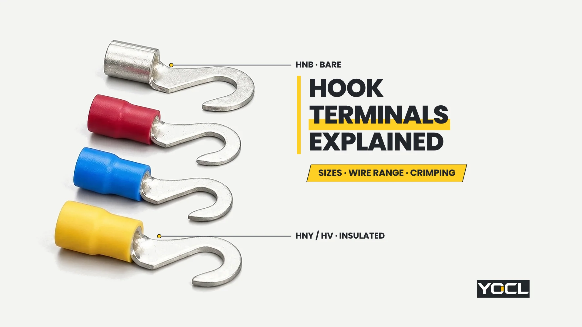
Hook terminals are cold-compression crimp connectors whose contact blade forms an open side-entry C-curve instead of a closed ring or a two-prong fork, allowing the terminal to slide sideways onto a loosened bolt or stud and lock under the screw head when tightened. Across YOCL ELECTRIC’s 65 models, three wire groups pair with five bolt openings.
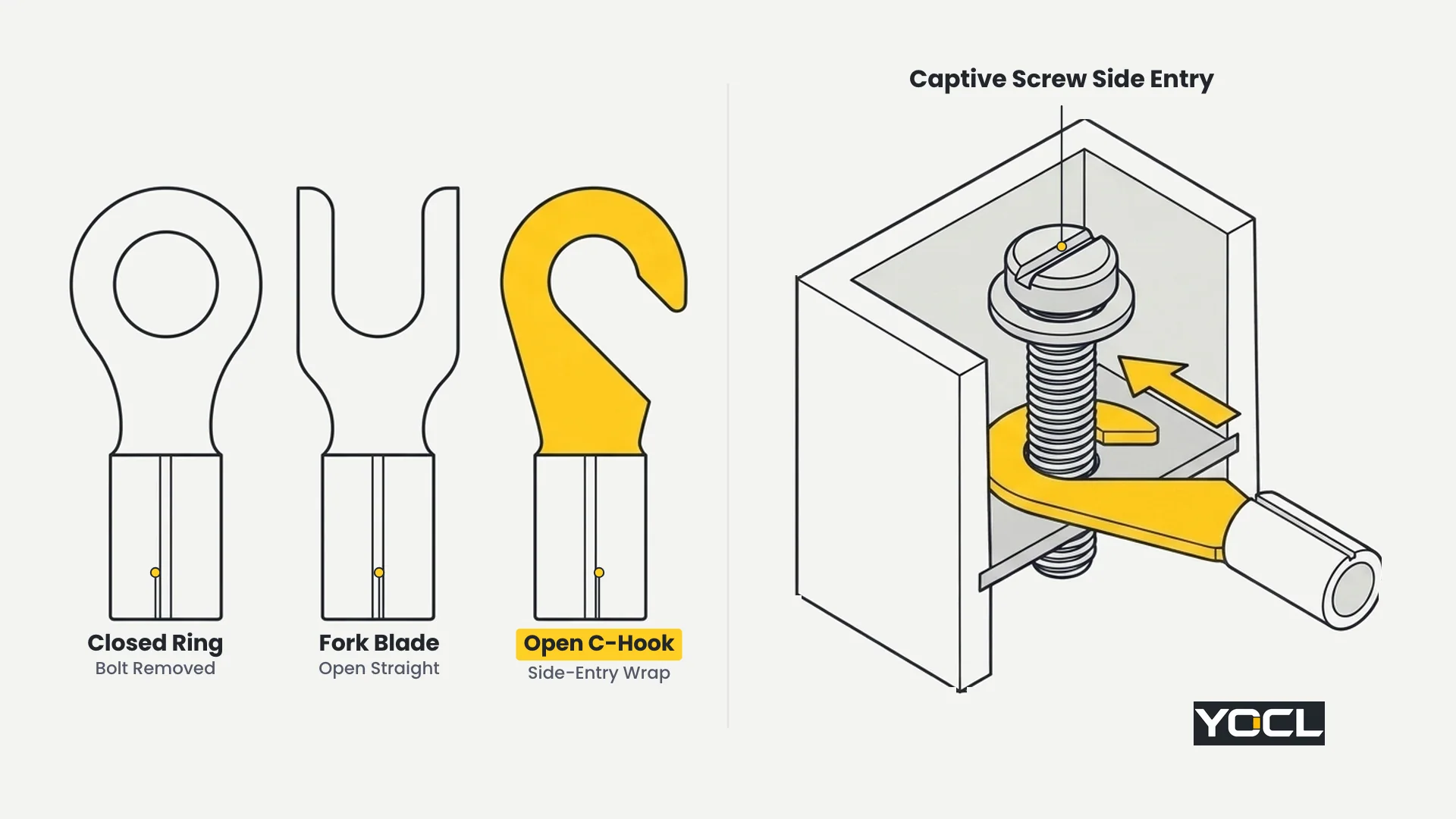
Engineers specify a hook blade for one practical installation problem: a bolted connection point where the screw can be loosened a few turns for wiring or retrofit work, but cannot—or should not—be backed out completely. A closed ring terminal cannot be installed without removing the screw entirely, whereas an open C-hook slips onto the shaft from the side in crowded terminal rows or captive-screw blocks. To keep neighbouring topics distinct, general crimp-terminal structure belongs to what a crimp terminal is, the choice between closed rings and two-prong forks belongs to ring vs spade terminals, and insulation-material properties belong to PVC vs nylon vs non-insulated crimp terminals.
Open-Hook Geometry vs Closed Rings: The Side-Entry Trade-Off
An open hook blade combines side-entry installation access with partial wrap around the screw shaft, sitting mechanically between a closed ring and a straight fork. However, the same side throat that lets the hook slide onto a loosened stud also allows it to slip sideways if the fastener works loose.
Treat that open throat as a direct geometric consequence rather than a hidden performance rating:
- Why the C-hook helps during service: Because the curved tip hooks around the back of the stud once seated, pulling straight backward along the wire axis draws the inner curve against the bolt shaft rather than sliding straight out like a parallel fork.
- Why it is not a captive joint: If thermal cycling or improper tightening leaves the screw head loose, sideways movement toward the open throat can still unhook the blade completely—something a closed ring physically prevents as long as the stud remains in place.
- Field selection rule: Specify a closed ring whenever the bolt can be removed and the wire must stay captive on the stud; specify a hook terminal where captive hardware or tight panel access demands side entry and screw clamping tightness is verified during assembly.
Hook Terminals Size System: Model Codes, Bolt Openings, and Full Charts
Selecting hook terminals accurately starts with decoding YOCL’s shared model-code system and three-group dimensional ladder across all 65 catalogue SKUs. Every model code pairs a conductor-range prefix with a nominal bolt-size suffix—and the nominal suffix after the dash is never equal to the measured hook opening d2.
Decoding the Shared Conductor and Bolt Ladder
All three YOCL families—bare copper HNB, nylon-insulated HNY/HNYD, and PVC-insulated HV/HVD—use the exact same model-code syntax: [Series] [Group]-[Bolt Code]. For example, HNB 2-5 identifies series HNB, conductor group 2 (1.5–2.5 mm²), and bolt code 5 (#10 bolt).
- Three shared conductor groups: Group 1.25 covers 0.5–1.5 mm²; Group 2 covers 1.5–2.5 mm²; Group 5.5 covers 4–6 mm². The insulated HNY/HNYD and HV/HVD pages also print the equivalent AWG 22–16, AWG 16–14, and AWG 12–10 ranges and color-code the sleeves Red (1.25), Blue (2), and Yellow (5.5), whereas the HNB page lists mm² only. Copper contact thickness across all three families is 0.7 mm (group 1.25), 0.8 mm (group 2), and 1.0 mm (group 5.5).
- Catalogue Imax label boundary: Across all three families, the group tables list Imax = 19 A (group 1.25), 27 A (group 2), and 48 A (group 5.5). As stated on YOCL’s product pages, Imax is the catalogue’s maximum-current label for the conductor group and test or installation conditions are not provided—never treat Imax as an installed circuit ampacity.
- Nominal bolt code vs actual opening d2: Each family lists 13 models per crimp style (4 in group 1.25, 4 in group 2, and 5 in group 5.5, where the 5/16 bolt size exists only in group 5.5). The number after the dash (3.5, 4, 5, 6, 8) is the nominal screw code, while d2 is the actual clearance opening in millimeters:
- Suffix -3.5 (#6 US bolt) → actual opening d2 = 3.7 mm
- Suffix -4 (#8 US bolt) → actual opening d2 = 4.3 mm
- Suffix -5 (#10 US bolt) → actual opening d2 = 5.3 mm
- Suffix -6 (1/4 US bolt) → actual opening d2 = 6.5 mm
- Suffix -8 (5/16 US bolt, group 5.5 only) → actual opening d2 = 8.5 mm
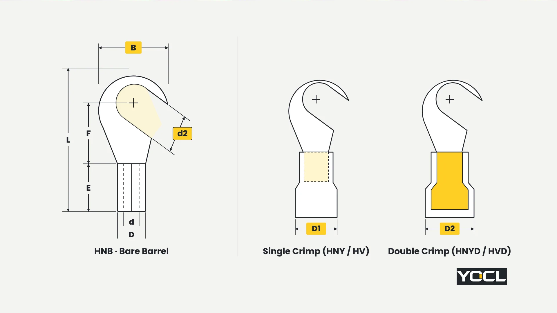
- Selection sequence: Match wire cross-section to the conductor group first, match the stud or screw size to d2 second, and check B (outer hook width), F (barrel top to bolt center), and L (overall length) against the barrier walls around the terminal post—because a hook slides on from the side, it requires lateral clearance beside the screw. (For tab-style disconnects that use a different sizing system, see the quick-disconnect terminal size chart.)
Family 1: HNB Non-Insulated Hook Terminals (TO Type)
YOCL’s HNB non-insulated hook terminals (TO type) are uninsulated copper terminals across 13 models, providing the shortest overall length L (15.7–27.0 mm) and bare barrels for direct visual inspection or post-crimp heat-shrink tubing.
Within each conductor group, copper thickness, barrel length E, barrel outer diameter D, and barrel inner diameter d are shared: Group 1.25 (0.5–1.5 mm², Imax 19 A without test/installation conditions stated) has thickness 0.7 mm, E = 4.8 mm, D = 3.4 mm, d = 1.7 mm; Group 2 (1.5–2.5 mm², Imax 27 A, no conditions stated) has thickness 0.8 mm, E = 4.8 mm, D = 4.1 mm, d = 2.3 mm; Group 5.5 (4–6 mm², Imax 48 A, no conditions stated) has thickness 1.0 mm, E = 6.0 mm, D = 5.6 mm, d = 3.4 mm.
| Model | Section (mm²) | Bolt | d2 (mm) | B (mm) | F (mm) | L (mm) | E (mm) | D (mm) | d (mm) |
|---|---|---|---|---|---|---|---|---|---|
| HNB 1.25-3.5 | 0.5–1.5 | #6 | 3.7 | 8.0 | 7.0 | 15.8 | 4.8 | 3.4 | 1.7 |
| HNB 1.25-4 | 0.5–1.5 | #8 | 4.3 | 8.0 | 7.0 | 15.8 | 4.8 | 3.4 | 1.7 |
| HNB 1.25-5 | 0.5–1.5 | #10 | 5.3 | 8.0 | 7.0 | 15.8 | 4.8 | 3.4 | 1.7 |
| HNB 1.25-6 | 0.5–1.5 | 1/4 | 6.5 | 11.6 | 11.0 | 21.8 | 4.8 | 3.4 | 1.7 |
| HNB 2-3.5 | 1.5–2.5 | #6 | 3.7 | 8.5 | 7.4 | 16.8 | 4.8 | 4.1 | 2.3 |
| HNB 2-4 | 1.5–2.5 | #8 | 4.3 | 8.5 | 7.4 | 16.8 | 4.8 | 4.1 | 2.3 |
| HNB 2-5 | 1.5–2.5 | #10 | 5.3 | 9.5 | 7.3 | 16.8 | 4.8 | 4.1 | 2.3 |
| HNB 2-6 | 1.5–2.5 | 1/4 | 6.5 | 12.0 | 11.0 | 21.8 | 4.8 | 4.1 | 2.3 |
| HNB 5.5-3.5 | 4–6 | #6 | 3.7 | 7.2 | 6.1 | 15.7 | 6.0 | 5.6 | 3.4 |
| HNB 5.5-4 | 4–6 | #8 | 4.3 | 9.5 | 9.5 | 19.8 | 6.0 | 5.6 | 3.4 |
| HNB 5.5-5 | 4–6 | #10 | 5.3 | 9.5 | 9.5 | 19.8 | 6.0 | 5.6 | 3.4 |
| HNB 5.5-6 | 4–6 | 1/4 | 6.5 | 12.0 | 10.3 | 22.5 | 6.0 | 5.6 | 3.4 |
| HNB 5.5-8 | 4–6 | 5/16 | 8.5 | 15.0 | 13.5 | 27.0 | 6.0 | 5.6 | 3.4 |
Selection Rule: Choose HNB bare copper models when minimal overall length L (15.7–27.0 mm) is required in tight spaces or when external heat-shrink tubing will be applied after crimping; switch to HNY/HNYD or HV/HVD whenever pre-insulated color-coded barrels are required.
Family 2: HNY (Single Crimp) and HNYD (Double Crimp) Nylon Hook Terminals
YOCL’s HNY/HNYD nylon hook terminals pair a copper contact with a nylon insulating sleeve across 13 matched single-crimp (HNY) and double-crimp (HNYD) rows (26 models). For this nylon family—and this family only—the product page states 600 V and 105 °C across all three size groups.
Group parameters pair Red (group 1.25: 0.5–1.5 mm² / AWG 22–16, thickness 0.7 mm, catalogue Imax 19 A without test/installation conditions), Blue (group 2: 1.5–2.5 mm² / AWG 16–14, thickness 0.8 mm, Imax 27 A, no conditions stated), and Yellow (group 5.5: 4–6 mm² / AWG 12–10, thickness 1.0 mm, Imax 48 A, no conditions stated).
| HNY (Single) | HNYD (Double) | Color | Bolt | d2 (mm) | B (mm) | F (mm) | L (mm) | E (mm) | D1 (mm) | D2 (mm) |
|---|---|---|---|---|---|---|---|---|---|---|
| HNY 1.25-3.5 | HNYD 1.25-3.5 | Red | #6 | 3.7 | 8.0 | 7.0 | 22.0 | 11.0 | 4.3 | 4.8 |
| HNY 1.25-4 | HNYD 1.25-4 | Red | #8 | 4.3 | 8.0 | 7.0 | 22.0 | 11.0 | 4.3 | 4.8 |
| HNY 1.25-5 | HNYD 1.25-5 | Red | #10 | 5.3 | 8.0 | 7.0 | 22.0 | 11.0 | 4.3 | 4.8 |
| HNY 1.25-6 | HNYD 1.25-6 | Red | 1/4 | 6.5 | 11.6 | 11.0 | 28.0 | 11.0 | 4.3 | 4.8 |
| HNY 2-3.5 | HNYD 2-3.5 | Blue | #6 | 3.7 | 8.5 | 7.4 | 23.0 | 11.0 | 4.9 | 5.2 |
| HNY 2-4 | HNYD 2-4 | Blue | #8 | 4.3 | 8.5 | 7.4 | 23.0 | 11.0 | 4.9 | 5.2 |
| HNY 2-5 | HNYD 2-5 | Blue | #10 | 5.3 | 9.5 | 7.3 | 23.0 | 11.0 | 4.9 | 5.2 |
| HNY 2-6 | HNYD 2-6 | Blue | 1/4 | 6.5 | 12.0 | 11.0 | 28.0 | 11.0 | 4.9 | 5.2 |
| HNY 5.5-3.5 | HNYD 5.5-3.5 | Yellow | #6 | 3.7 | 7.2 | 6.1 | 23.7 | 14.0 | 6.9 | 7.2 |
| HNY 5.5-4 | HNYD 5.5-4 | Yellow | #8 | 4.3 | 9.5 | 9.5 | 27.8 | 14.0 | 6.9 | 7.2 |
| HNY 5.5-5 | HNYD 5.5-5 | Yellow | #10 | 5.3 | 9.5 | 9.5 | 27.8 | 14.0 | 6.9 | 7.2 |
| HNY 5.5-6 | HNYD 5.5-6 | Yellow | 1/4 | 6.5 | 12.0 | 10.3 | 30.5 | 14.0 | 6.9 | 7.2 |
| HNY 5.5-8 | HNYD 5.5-8 | Yellow | 5/16 | 8.5 | 15.0 | 13.5 | 35.0 | 14.0 | 6.9 | 7.2 |
Selection Rule: Choose HNY/HNYD when the specification requires nylon insulation with stated 600 V and 105 °C group parameters; select HNYD (D2 = 4.8 / 5.2 / 7.2 mm) over HNY (D1 = 4.3 / 4.9 / 6.9 mm) when a double-crimp barrel over the wire insulation is needed.
Family 3: HV (Single Crimp) and HVD (Double Crimp) PVC Pre-Insulated Hook Terminals
YOCL’s HV/HVD pre-insulated hook terminals pair a copper contact with a PVC sleeve across 13 matched pairs (26 models), where HVD incorporates an additional copper tube with sleeve described on the source page as double pressure.
Group wire ranges (Red 0.5–1.5 mm² / AWG 22–16; Blue 1.5–2.5 mm² / AWG 16–14; Yellow 4–6 mm² / AWG 12–10), copper thicknesses (0.7 / 0.8 / 1.0 mm), and catalogue Imax labels (19 A / 27 A / 48 A, without test or installation conditions stated) match the shared ladder, while the HV/HVD page states no voltage or temperature rating.
| HV (Single) | HVD (Double) | Color | Bolt | d2 (mm) | B (mm) | F (mm) | L (mm) | E (mm) | D1 (mm) | D2 (mm) |
|---|---|---|---|---|---|---|---|---|---|---|
| HV 1.25-3.5 | HVD 1.25-3.5 | Red | #6 | 3.7 | 8.0 | 7.0 | 21.0 | 10.0 | 4.3 | 4.5 |
| HV 1.25-4 | HVD 1.25-4 | Red | #8 | 4.3 | 8.0 | 7.0 | 21.0 | 10.0 | 4.3 | 4.5 |
| HV 1.25-5 | HVD 1.25-5 | Red | #10 | 5.3 | 8.0 | 7.0 | 21.0 | 10.0 | 4.3 | 4.5 |
| HV 1.25-6 | HVD 1.25-6 | Red | 1/4 | 6.5 | 11.6 | 11.0 | 27.0 | 10.0 | 4.3 | 4.5 |
| HV 2-3.5 | HVD 2-3.5 | Blue | #6 | 3.7 | 8.5 | 7.4 | 22.0 | 10.0 | 4.9 | 5.2 |
| HV 2-4 | HVD 2-4 | Blue | #8 | 4.3 | 8.5 | 7.4 | 22.0 | 10.0 | 4.9 | 5.2 |
| HV 2-5 | HVD 2-5 | Blue | #10 | 5.3 | 9.5 | 7.3 | 22.0 | 10.0 | 4.9 | 5.2 |
| HV 2-6 | HVD 2-6 | Blue | 1/4 | 6.5 | 12.0 | 11.0 | 27.0 | 10.0 | 4.9 | 5.2 |
| HV 5.5-3.5 | HVD 5.5-3.5 | Yellow | #6 | 3.7 | 7.2 | 6.1 | 22.7 | 13.0 | 6.7 | 7.0 |
| HV 5.5-4 | HVD 5.5-4 | Yellow | #8 | 4.3 | 9.5 | 9.5 | 26.8 | 13.0 | 6.7 | 7.0 |
| HV 5.5-5 | HVD 5.5-5 | Yellow | #10 | 5.3 | 9.5 | 9.5 | 26.8 | 13.0 | 6.7 | 7.0 |
| HV 5.5-6 | HVD 5.5-6 | Yellow | 1/4 | 6.5 | 12.0 | 10.3 | 29.5 | 13.0 | 6.7 | 7.0 |
| HV 5.5-8 | HVD 5.5-8 | Yellow | 5/16 | 8.5 | 15.0 | 13.5 | 34.0 | 13.0 | 6.7 | 7.0 |
Selection Rule: Choose HV (single crimp, D1 = 4.3 / 4.9 / 6.7 mm) or HVD (double-pressure copper tube + PVC sleeve, D2 = 4.5 / 5.2 / 7.0 mm) when standard PVC pre-insulated hook terminals with 1.0 mm shorter sleeve lengths E (10.0 / 10.0 / 13.0 mm) and overall lengths L (21.0–34.0 mm) fit the panel layout.
Three Hook-Terminal Families on One Shared Dimensional Ladder
Comparing HNB, HNY/HNYD, and HV/HVD side by side shows that all 65 models share one identical contact-blade ladder—every matching suffix has the exact same d2 opening, outer hook width B, neck length F, and copper thickness. Only the barrel insulation, sleeve length E, and overall length L change.
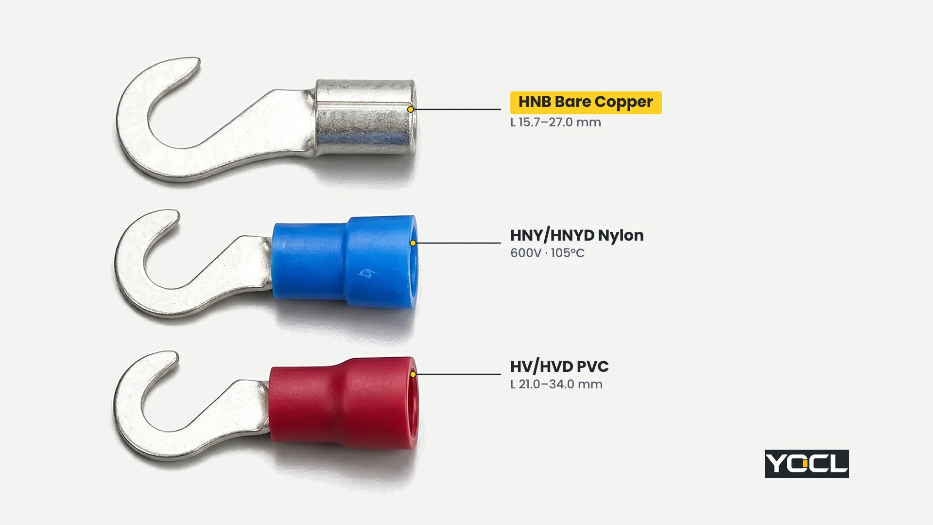
Because the hook blade itself never changes between families for a given model suffix, switching between bare, nylon, and PVC versions affects only the wire-entry barrel:
- HNB (TO type): Uninsulated copper barrel with E = 4.8 / 4.8 / 6.0 mm and the shortest overall lengths (L = 15.7–27.0 mm).
- HNY and HNYD: Nylon-insulated single-crimp and double-crimp barrels with E = 11.0 / 11.0 / 14.0 mm, L = 22.0–35.0 mm, and stated 600 V / 105 °C group ratings.
- HV and HVD: PVC pre-insulated single-crimp and double-pressure barrels with E = 10.0 / 10.0 / 13.0 mm and L = 21.0–34.0 mm (each 1.0 mm shorter in E and L than the corresponding HNY/HNYD row). For how PVC, nylon, and non-insulated sleeves compare in application, see PVC vs nylon vs non-insulated crimp terminals.
Single Crimp vs Double Crimp Barrels: D1, D2, and Die Matching
In both insulated families, the single-crimp versions (HNY, HV) and double-crimp versions (HNYD, HVD) differ in barrel construction and outer entry diameter: every double-crimp model carries a larger barrel diameter D2 > D1, providing a second compression zone over the wire insulation alongside the conductor crimp.
Look at how the published barrel diameters step up from D1 (single crimp) to D2 (double crimp) across all three wire groups:
- Group 1.25 (Red, 0.5–1.5 mm²): HNY D1 = 4.3 mm vs HNYD D2 = 4.8 mm; HV D1 = 4.3 mm vs HVD D2 = 4.5 mm.
- Group 2 (Blue, 1.5–2.5 mm²): HNY D1 = 4.9 mm vs HNYD D2 = 5.2 mm; HV D1 = 4.9 mm vs HVD D2 = 5.2 mm.
- Group 5.5 (Yellow, 4–6 mm²): HNY D1 = 6.9 mm vs HNYD D2 = 7.2 mm; HV D1 = 6.7 mm vs HVD D2 = 7.0 mm.
As the HV/HVD specification page notes, the HVD double-crimp barrel contains an additional internal copper tube inside the sleeve—referred to as a double-pressure construction—so closing the crimping tool compresses the primary copper barrel onto the stripped conductor strands while the rear section grips the wire insulation jacket. Match the crimping die cavity strictly to the chosen construction (D1 vs D2): crimping a larger D2 double-crimp barrel in a narrow single-crimp die setting crushes the sleeve unevenly and damages the insulation entry.
Frequently Asked Questions
Should I choose a hook terminal or a ring terminal?
Access to the fastener decides. Choose a closed ring terminal whenever the screw or nut can be removed completely and the wire must remain captive on the stud. Choose a hook terminal when captive hardware or tight spacing allows loosening the screw only a few turns and clamp tightness is verified; see ring vs spade terminals.
What does the number after the dash mean in a hook terminal code?
The number after the dash (3.5, 4, 5, 6, or 8) is the nominal screw code, not the measured hook opening. Always read the actual clearance opening d2 from the table: code 3.5 (#6 bolt) has d2 = 3.7 mm, 4 (#8) has 4.3 mm, 5 (#10) has 5.3 mm, 6 (1/4) has 6.5 mm, and 8 (5/16) has 8.5 mm.
Can a hook terminal go on a bolt one size larger than its chart row?
No. The hook opening d2 is sized to clear its designated bolt shaft (#6 through 5/16) and seat around the stud center. Forcing a smaller hook onto the next bolt size up prevents the C-curve from seating around the shaft, while using an oversized hook leaves minimal contact area under the screw head and lets the blade slip off easily.
Should I specify single crimp (HNY / HV) or double crimp (HNYD / HVD)?
Specify single crimp (HNY or HV, barrel diameter D1) when standard conductor-only compression in a flared insulating skirt fits your crimping tool; specify double crimp (HNYD or HVD, larger barrel diameter D2 > D1 with an inner copper sleeve on HVD) when you need a second grip section over the wire insulation and have a matching double-crimp die.
References
- YOCL ELECTRIC Product Information — HNB Non-Insulated Hook Terminals (TO Type): bare copper specifications, group Imax labels, and 13-model dimensional table.
- YOCL ELECTRIC Product Information — HNY/HNYD Nylon Hook Terminals (Single and Double Crimp): nylon-insulated single-crimp (D1) and double-crimp (D2) specifications, 600 V and 105 °C group ratings, and 13 paired model rows.
- YOCL ELECTRIC Product Information — HV/HVD Pre-Insulated Hook Terminals: PVC-insulated single-crimp (HV) and double-pressure additional-copper-tube (HVD) specifications and 13 paired model rows.