
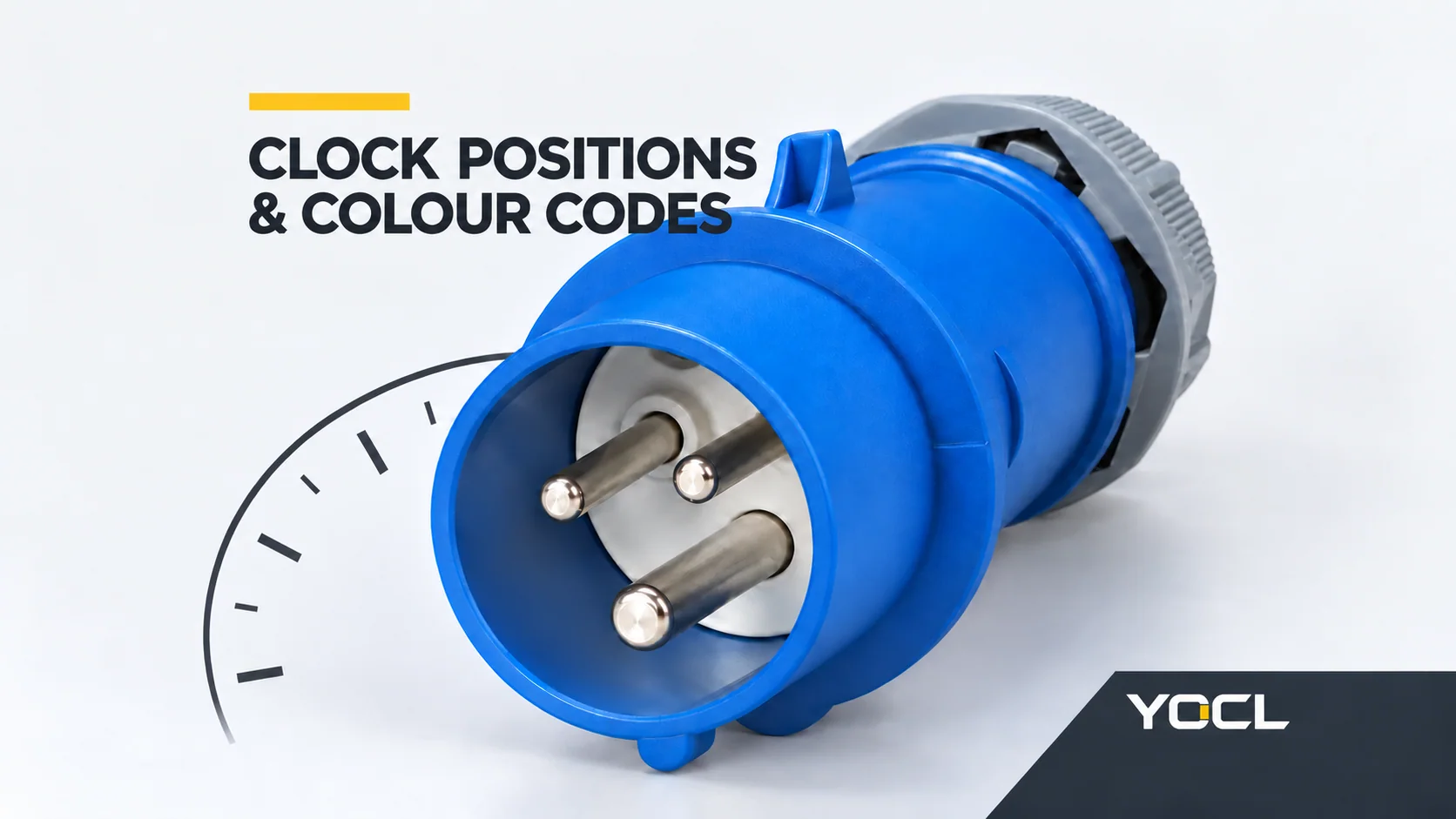
La couleur d'une fiche industrielle est un indicateur de la famille de tension ; son code d'horloge, tel que 4h, 6h ou 9h, identifie une position de codage mécanique. Lisez les deux conjointement avec la disposition des pôles et les indications imprimées. Le bleu n'identifie pas toutes les caractéristiques d'un connecteur, et 6h ne signifie pas toujours 230 V.
Ce guide couvre le système de lecture familier des broches et manchons IEC 60309 pour les accessoires ci-dessus 50 V. Pour les différences plus générales entre les fiches, coupleurs, prises et entrées d'appareils, voir Fiches et prises industrielles expliquées.
Établissez la vue avant de lire l'heure
Pour les accessoires ci-dessus 50 V, lisez le tube de contact de terre dans la vue de face de la prise, keyway at six o’clock. The corresponding plug retains that code: IEC 60309-2:2021, clause 7.1, public sample, printed page 11.
Read the reference view as follows:
- Face the socket’s mating side.
- Turn the main keyway downward.
- Compare the earth contact position with a clock face.
In that view, 6h is at the bottom, 9h is at the left, and 4h is toward the lower right. The letter h records a clock position; it is not a duration or a count of phases.
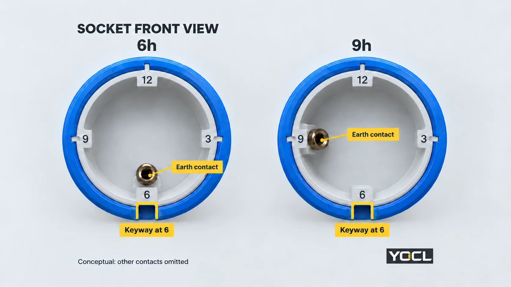
Socket-front orientation is not a rear-terminal map. Use the manufacturer’s drawing for terminal identification; do not assign terminals from an unlabeled photograph.
Common Colour and Clock Combinations in YOCL’s Catalogue
The table below is a selected YOCL catalogue lookup, not a reproduction of every IEC voltage/frequency combination. Values and model identifiers come from the published YOCL IP44 industrial plug tables.
| Body colour | Disposition des pôles | Listed operating voltage | Position de l'horloge | Example model | Courant nominal |
|---|---|---|---|---|---|
| Jaune | 2P+E | 110–130 V | 4h | NM-013H-4 | 16 A |
| Bleu | 2P+E | 220–240 V | h 6 | NM-013H | 16 A |
| Rouge | 3P+E | 380–415 V | h 6 | NM-014H | 16 A |
| Rouge | 3P+N+E | 220–380 / 240–415 V, as listed | h 6 | NM-015H | 16 A |
| Rouge | 2P+E | 380–415 V | 9h | NM-013L-9 | 16 A |
| Bleu | 3P+E | 220–240 V | 9h | NM-014L-9 | 16 A |
E denotes protective earth; N denotes neutral. The pole expressions above correspond to three, four and five main contacts respectively. A three-contact 2P+E expression alone does not identify the circuit as phase-plus-neutral rather than phase-plus-phase; read the supply and terminal documentation.
For the five-contact row, the voltage text is preserved from the catalogue. Do not turn its paired notation into a single assumed supply voltage. Confirm the intended phase-to-neutral and phase-to-phase values when specifying that model.
The selected plug tables do not state a frequency for these rows. The YOCL range selector requests frequency as a separate specification input, so record it rather than assuming a catalogue omission means unrestricted use.
What the Colours Let You Recognize
Within these catalogue examples, yellow identifies the listed 110–130 V option, blue the listed 220–240 V options, and red the listed 380–415 V options and the five-contact paired-voltage entry. These are useful visual starting points for sorting the catalogue.
Le printed operating-voltage marking is the precise input. A nominal supply label, a broad colour-code band and a particular model’s declared voltage range should not be treated as interchangeable. Other colour bands, frequency-specific configurations and regional series need their own applicable table; this shortlist cannot select them.
Read the Pole Row Before the Clock Sector
A circular clock chart can contain several rings. Start with the ring for the actual pole arrangement, then read its voltage/frequency sector and earth position. Reading the same sector across a different ring can produce a different connector specification.
Two comparisons from the table make the problem concrete.
Same Blue Colour, Different Clock Codes
NM-013H and NM-014L-9 are both listed as blue, 16 A and 220–240 V. However:
- NM-013H: 2P+E, three contacts, h 6.
- NM-014L-9: 3P+E, four contacts, 9h.
A request for a “blue 16 A industrial plug” leaves the pole arrangement and clock designation unresolved. The two rows describe different interfaces, despite sharing colour, current and listed voltage.
Same 6h Code, Different Voltage and Contacts
NM-013H and NM-014H both have a 6h designation and a listed 16 A rating. The first is blue, 2P+E and 220–240 V; the second is red, 3P+E and 380–415 V.
Consequently, “6h plug” is incomplete, just as “blue plug” is incomplete. Clock coding needs the other fields to become a meaningful specification. Neither example establishes permission to adapt one circuit to another.
Separate the Information on the Marking
Separate current, clock code and voltage before comparing parts. Below, NM-013H’s catalogue values appear as three external annotations, rather than a transcription of a physical rating plate.
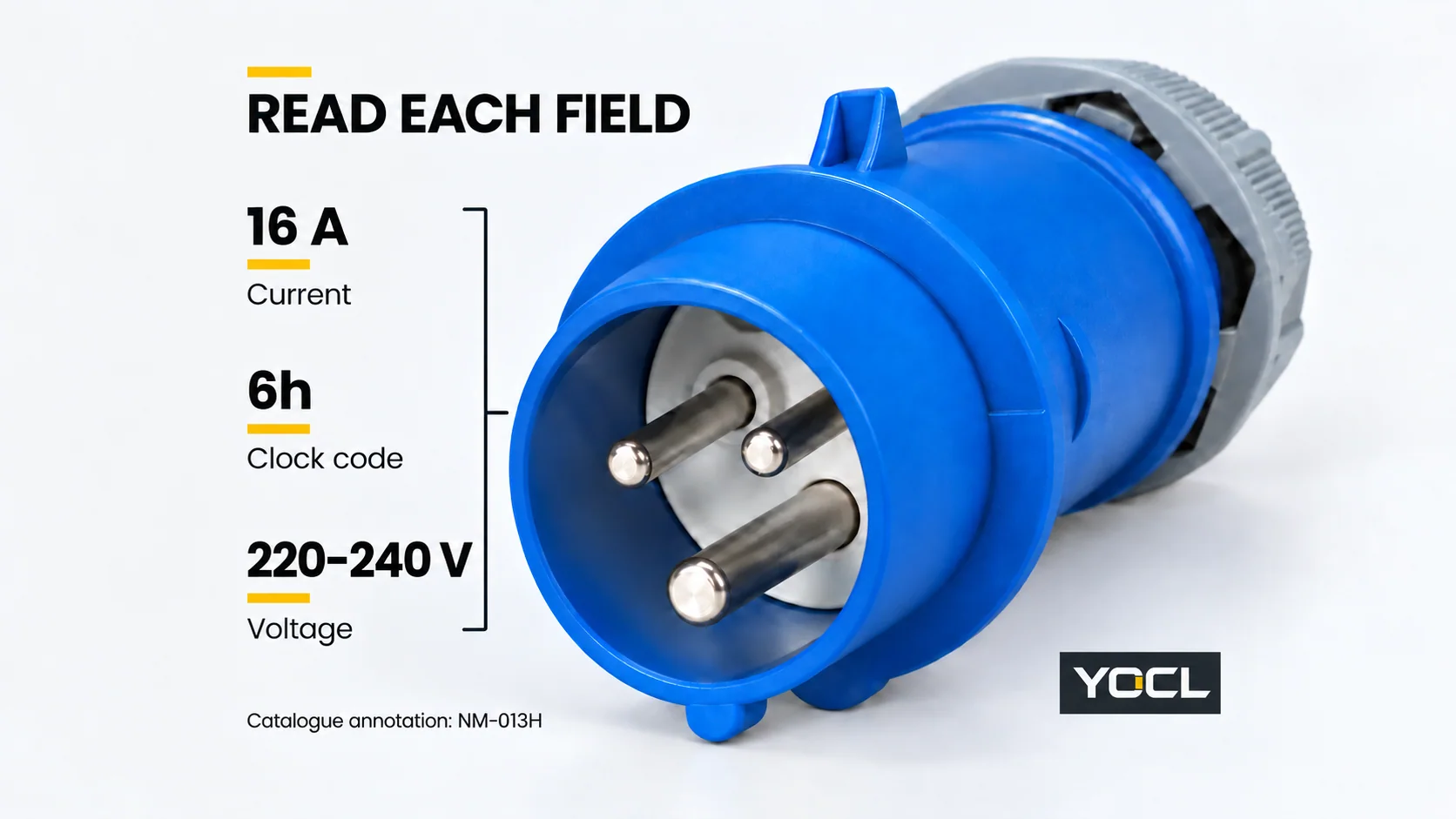
Use this record when reading a product or requesting its mating part:
| Record separately | What to copy or confirm |
|---|---|
| Component format | Plug, portable cable coupler, fixed socket or appliance inlet |
| Disposition des pôles | Full expression, such as 2P+E or 3P+N+E |
| Courant nominal | Exact ampere value and applicable size series |
| Operating voltage and supply | Full marking, including paired values and AC/DC identification where given |
| Fréquence | Published marking or confirmed model specification |
| Clock designation | Complete number plus h, interpreted in the correct reference view |
| Environmental and mechanical details | Required protection, locking arrangement, cable entry or mounting format |
| Mating accessory | Exact existing part identifier, photograph and manufacturer’s compatibility confirmation |
Colour can accompany this record, but cannot replace its electrical or mechanical fields. Likewise, an IP marking concerns protection and does not tell you the clock position.
Where This Reading Method Stops
At or below 50 V, the minor key supplies the clock reference, relative to the major key. This guide’s earth-contact rule does not apply.
Special supply systems need the full applicable reference. Do not fill unlisted clock sectors with guesses or select a high-frequency or DC connector from a familiar mains-colour example. Check the relevant standard configuration and the model’s documentation.
Coding is not an installation approval. IEC 60309-1:2021 covers general accessory requirements; IEC 60309-2:2021 addresses dimensional compatibility for standardized pin-and-contact-tube accessories. IEC’s current Part 2 publication includes an August 2026 correction. The clause-reading explanations here use the accessible original 2021 sample; that sample is not the full corrected publication or evidence of any individual product’s certification.
For a replacement, use the existing accessory’s full designation to start the enquiry. YOCL’s industrial plugs and sockets range et IP44 cable coupler catalogue provide product routes. Send the specification record and the existing mating-part details for confirmation before ordering; the clock diagram does not establish wiring, circuit protection or suitability for the installation.
Références
- IEC — IEC 60309-2:2021 public sample, edition 5.0, original 2021 text: clause 7.1. Limited sample; not the full August 2026 corrected publication.
- YOCL ELECTRIC — IP44 fiches industrielles, published model tables accessed 11 October 2026; first-party catalogue declarations.
- YOCL ELECTRIC — Industrial plugs and sockets range, specification selector accessed 11 October 2026; first-party information.
- IEC — IEC 60309-1:2021, General requirements, edition 5.0; official scope and publication information.
- IEC — IEC 60309-2:2021, Dimensional compatibility requirements, edition 5.0 including COR1:2026; official current publication information.