
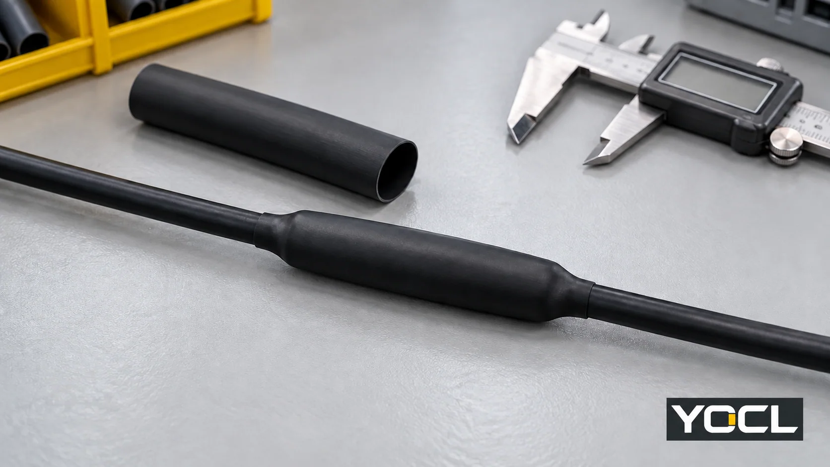
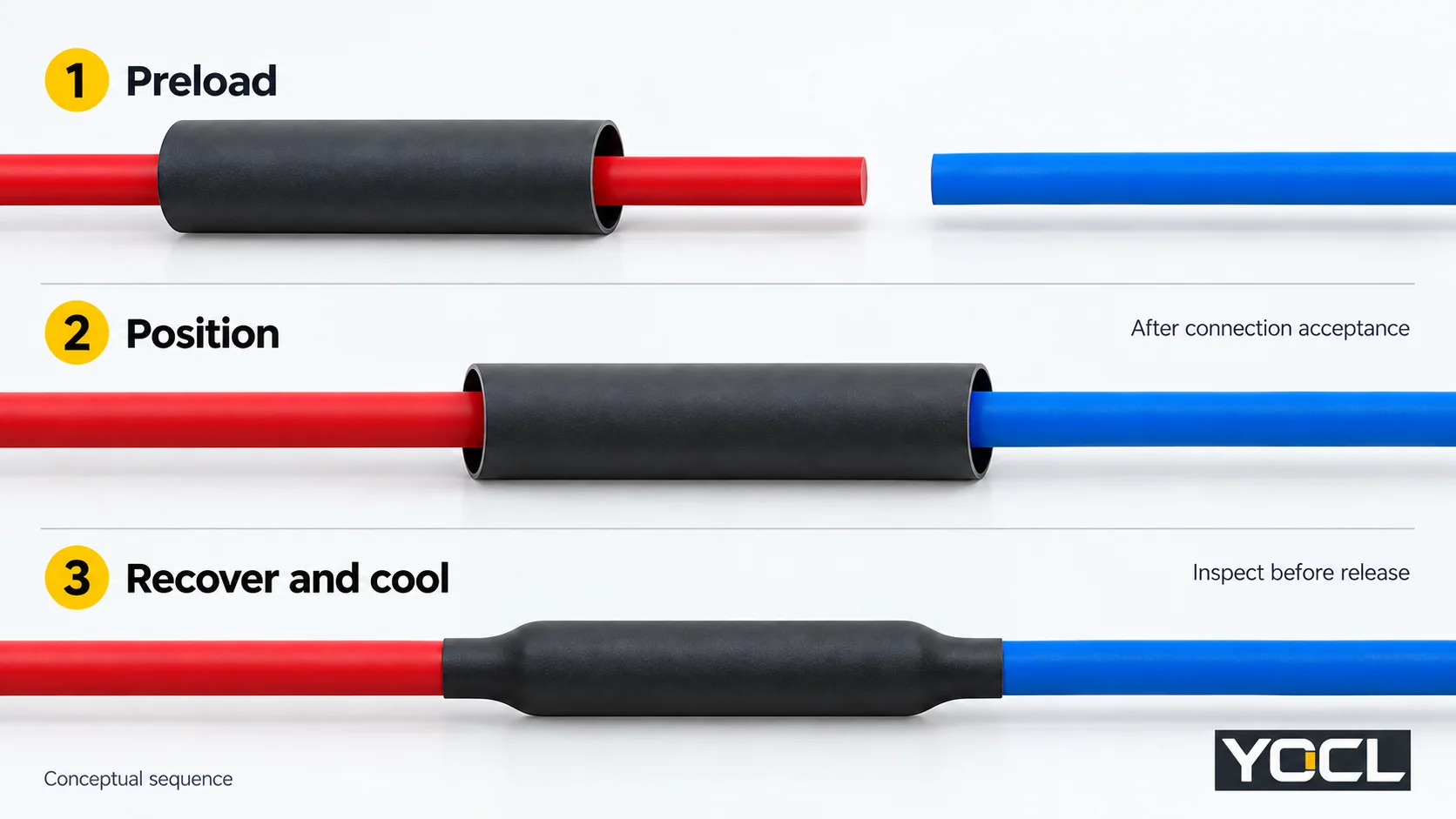
Choisissez un manchon thermorétractable qui passe sur la plus grande partie de l'épissure, se rétracte en dessous du plus petit diamètre de connexion et conserve la couverture requise après rétraction. Coupez-le et préchargez-le avant de fermer la connexion, acceptez la jonction électrique, positionnez le manchon, rétractez-le avec le processus de chauffage spécifié, puis refroidissez, inspectez et terminez les tests d'assemblage requis.
Cette procédure couvre une épissure droite en ligne spécifiée. Gaines thermorétractables fournit l'isolation ou la protection spécifiée ; elle ne réalise pas la connexion électrique. Les jonctions blindées, multiconducteurs et moyenne ou haute tension nécessitent leurs propres instructions d'assemblage. Un manchon rétracté de manière serrée ne prouve pas qu'une jonction est électriquement acceptable ou scellée de manière environnementale.
1. Confirmez les instructions de travail et l'isolement
Avant de couper le câble ou d'appliquer de la chaleur, obtenez le schéma d'épissure, les instructions de jonction, les données exactes du manchon, le processus d'application et les exigences d'acceptation. Travaillez sur un circuit isolé vérifié hors tension selon la procédure de l'équipement et du site. Dans les U.S workplaces, OSHA 1910.333(b) définit le verrouillage/l'étiquetage et la vérification par une personne qualifiée.
Utilisez un enregistrement de travail pour relier les mesures à la décision d'acceptation éventuelle :
| Enregistrement avant le démarrage | Décision qu'il contrôle |
|---|---|
| Identification du câble/gaine, du raccord et du manchon | Compatibilité des matériaux et instructions applicables |
| Plus grande caractéristique sur le chemin d'insertion du manchon | Diamètre intérieur fourni requis |
| Diamètres extérieurs d'atterrissage gauche et droit | Rétraction requise des deux côtés |
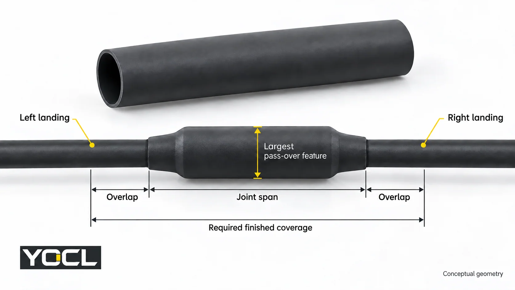
| Écartement du joint et chevauchement spécifié de chaque côté | Couverture finie minimale |
| Usage électrique, environnement et espace disponible | Construction, mur et aptitude à l'assemblage |
| Instructions de chauffage, de refroidissement et d'acceptation | Limites du processus et vérifications de libération |
Avoir à disposition des outils de mesure appropriés, une pince coupante, les outils d'assemblage spécifiés et une source de chaleur contrôlée autorisée. Retenir le travail si une instruction requise ou un critère d'acceptation est manquant.
2. Sélectionnez la construction et vérifiez les deux diamètres
Choisissez la construction pour la tâche spécifiée. La gamme de tubes thermorétractables YOCL comprend les tubes à paroi simple HTS et les tubes à paroi simple avec adhésif HS3X/HS4X. Un manchon non doublé peut répondre à une exigence d'isolation/protection ; un manchon doublé d'adhésif nécessite une interface de gaine compatible et un processus d'application vérifié lorsque l'étanchéité est requise. Utilisez le guide paroi simple vs paroi double si cette décision reste non résolue.
Mesurez le trajet d'insertion complet, y compris toute épaule de connecteur que le manchon doit franchir. Enregistrez séparément les deux diamètres d'atterrissage ; la section transversale du conducteur n'est pas un diamètre de gaine. Vérifiez le diamètre intérieur minimum fourni par rapport à la plus grande caractéristique de passage et le diamètre intérieur maximum récupéré par rapport au plus petit atterrissage.
Le principe plus grand avant/plus petit après apparaît dans KSC-E-165 Revision F, §3.8.1.1.1(a), a specification for KSC ground-support control and monitoring equipment. It supports this dimensional screen, not a universal installation margin.
For example, assume a 7.4 mm largest pass-over feature and a 4.0 mm smallest landing. The current YOCL HS3X table gives:
| HS3X nominal size | Supplied ID | Recovered ID | Preliminary result |
|---|---|---|---|
| 6.4 mm | ≥6.4 mm | ≤2.2 mm | Guaranteed supplied minimum does not clear 7.4 mm |
| 9.5 mm | ≥9.5 mm | ≤3.2 mm | Clears both basic diameter checks |
The 9.5 mm row is a dimensional candidate, not an approved sealed splice. Confirm the required insertion allowance, tolerances, wall/space, duty and jacket compatibility. Consult the size chart for other rows; use the shrink-ratio comparison when passage and landing geometry demand another ratio.
3. Determine cut length and preload the sleeve
Finished coverage must include the joint span and the specified overlap on each side. Allow for longitudinal change using the applicable process data. Do not substitute an arbitrary extra-length percentage or a laboratory axial-change value for an established installation allowance.
Where the instructions establish a maximum shortening fraction s, a planning calculation is:
Minimum cut length = (joint span + left overlap + right overlap) ÷ (1 − s)
Use the specified overlap and validated s for that application, round up to the permitted cut length, and verify actual coverage after cooling. If those inputs are unknown, the calculation cannot release the sleeve for cutting.
de YOCL HTS installation notes direct cutting to the required length and sliding tubing on before completing the connection when necessary. Preload the selected sleeve while access remains. Park it clear of the connection-making area under the joining instructions.
If access has been closed without preloading, stop for an approved correction; slitting a standard closed tube does not make it an approved wraparound sleeve.
4. Complete and accept the connection before covering it
Make the splice using its specified connector, conductor combination and joining procedure. Complete the required connection inspection before the sleeve conceals the joint. A failed or undocumented connection remains on hold even if the tubing fits.
Prepare the landing surfaces according to the selected jacket, sleeve and adhesive instructions. If they require cleaning, priming or drying, follow those material-specific directions. Do not improvise a solvent or abrasion method. For an adhesive-lined sealing job, unresolved surface compatibility or preparation means the sleeve is not ready for application.
5. Position the sleeve to the drawing
Move the sleeve into its specified position and check coverage at both ends.
Expected result: the joint and both required landing overlaps lie within the intended finished coverage. Reposition before heating if one end lacks coverage; extra material on the other end does not satisfy that requirement.
6. Recover with the specified heating process
HTS requires uniform recovery with controlled, even heat; other models need their applicable process.
Use the heat source, heating sequence, exposure limits and completion criteria established for the actual assembly. A catalogue shrink temperature is not a heat-gun dial setting, nozzle distance or dwell time. If these process requirements are unresolved, obtain the applicable instructions before heating.
NASA-STD-8739.4A Change 4, §9.9, in its NASA mission-hardware scope, ties heat and exposure to tubing size/type and requires protection of the covered item and nearby heat-sensitive parts. These are useful workmanship boundaries; they do not establish settings for a YOCL splice.
Hold the assembly if the specified recovery cannot be completed within its thermal limits or visible heat damage develops.
7. Cool and inspect the application
Let HTS cool before handling; follow the selected assembly’s cooling and inspection instructions. Check:
- Position and actual finished coverage against the drawing.
- Uniform recovery and grip where required.
- Cracks, punctures, blisters or burned areas, plus damage to the cable jacket.
- Any model-specific adhesive and interface acceptance criteria.
NASA-STD-8739.4A §§9.10–9.11 provide scoped examples of positioning, recovery/grip and visible defect checks. Appearance alone does not establish electrical performance or a complete hidden adhesive bond. An adhesive bead can be a specified local process cue; by itself it does not prove an environmental seal.
Route defects or unresolved sealing to the applicable rework process. The split-or-fail-to-seal guide explains the separate diagnosis task; do not keep reheating without authorized rework instructions.
8. Complete the release record before restoration
Record three separate decisions: connection accepted, sleeve workmanship accepted, et required assembly tests passed. Enter the cable/splice and sleeve identification, measured coverage, process reference and test results. A missing seal-verification requirement cannot be replaced with “looks tight.”
Complete the specified electrical and, where required, environmental acceptance tests using the assembly procedure. Hold failed or incomplete results. Restore service only through the equipment/site authorization process; OSHA 1910.333(b)(2)(v) sets out restoration checks for its U.S. workplace scope.
For YOCL model selection, provide the pass-over dimension, both landing diameters, required coverage, jacket material and duty when requesting the applicable tubing and process documentation. That information turns a catalogue size candidate into a reviewable application choice.
Références
- OSHA — 29 CFR 1910.333, electrical work practices, verification and restoration.
- YOCL — Heat Shrink Tubing, current product families.
- NASA KSC — KSC-E-165 Revision F, §3.8.1.1.1(a), dimensional selection.
- YOCL — HS3X 3:1 Dual-Wall Tubing, supplied/recovered size table.
- YOCL — HTS 2:1 Single-Wall Tubing, Installation Notes.
- NASA — NASA-STD-8739.4A Change 4, §§9.9–9.11, heating and workmanship.