
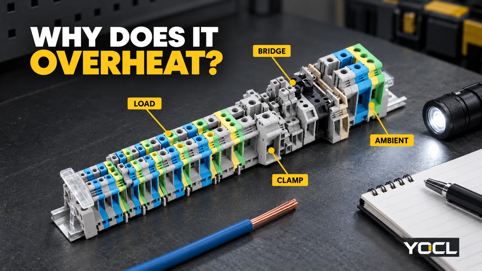
Blok terminal yang terlalu panas dapat melibatkan arus berlebih untuk kondisi persisnya, peningkatan resistansi kontak, persiapan konduktor yang tidak sesuai, jembatan atau jalur aksesori yang kelebihan beban, suhu sekitar yang tinggi, pembuangan panas yang terbatas, atau komponen yang rusak. Hentikan penggunaan peralatan jika terminal berubah warna, hangus, berubah bentuk, atau berbau panas, dan minta orang yang berkualifikasi untuk mengisolasi dan memverifikasinya sebelum diperiksa. Jangan mengencangkan, melepaskan, atau menyentuh konduktor saat rakitan dialiri listrik.
Sedikit kenaikan suhu adalah normal karena arus melewati resistansi listrik. Oleh karena itu, pertanyaan yang berguna bukanlah sekadar “apakah hangat?” tetapi apakah panasnya bersifat lokal, meningkat seiring waktu, terkait dengan komponen yang rusak, berulang setelah penyambungan kembali, atau ada hanya di bawah beban tertentu. Pemeriksaan di bawah ini menghubungkan bukti tersebut dengan tindakan selanjutnya yang dapat dipertahankan.
Poin Penting
- Bandingkan arus sirkuit yang terukur dengan baris model terminal yang tepat, termasuk kondisi kelistrikan dan instalasinya yang dinyatakan. Rentang konduktor yang lebih luas tidak secara otomatis menetapkan peringkat arus yang lebih tinggi.
- Increased contact resistance can arise from an incomplete insertion, wrong conductor preparation, an unsuitable conductor count, inadequate clamping or a loosened connection.
- A jumper, bridge, comb busbar or other accessory can form a current path with its own product and arrangement limits.
- Ambient heat, nearby equipment, enclosure ventilation and mounting density can change the terminal’s temperature without making the load itself faulty.
- Visible damage, repeated overheating or repeated loosening calls for replacement or escalation. Re-tightening a hot connection and returning it to service can leave the real cause unresolved.
Begin with the safe stop
Treat evidence of an active electrical fault as a reason to stop the process, not to experiment. The UK Health and Safety Executive explains that electrical equipment can deteriorate in service and that burn marks or stains may indicate overheating; affected equipment should be removed from use and checked by a competent person (HSE electrical guidance).
Have a qualified person follow the applicable site and equipment procedure to isolate the circuit and verify that it is de-energized. Keep records before parts are moved: circuit identifier, terminal model, conductor links, bridge arrangement, load state, ventilation route and photographs of the original layout. Preserve damaged parts where possible.
These actions are investigation boundaries, not steps for unqualified repair:
- Do not touch, re-tighten, remove or test a conductor or screw while it is live.
- Do not reclose the circuit merely because the terminal has cooled.
- Do not clean away discolouration, melts or loose material before the condition has been documented.
- Do not replace one terminal with a visually similar part until its model rating, conductor data, accessory fit and circuit function have been checked.
A hot surface is evidence, not a diagnosis
Terminal blocks normally become warmer than their surroundings because the current path is not a perfect conductor. IEC 60947-7-1:2025 addresses industrial support-mounted terminal blocks for round copper conductors and includes temperature-rise and voltage-drop requirements and tests. The public preview describes controlled sample, ambient, mounting and test conditions (IEC 60947-7-1:2025). An inspection inside an operating panel is not that controlled test setup.
This distinction matters because a single reading can be affected by the measurement method, adjacent heat sources, the load cycle and the chosen reference point. Use changes and patterns as diagnostic evidence, and obtain any acceptance threshold from the exact product instruction, equipment standard or responsible engineer.
| Observation | What the evidence supports | What it cannot establish on its own |
|---|---|---|
| The whole row is warm and similar under the same load | Normal current-related temperature rise is one possibility | That the current, connection or installation is acceptable |
| One terminal is much hotter than identical terminals carrying similar current | A local current-path or connection difference deserves investigation | That a loose screw alone is the cause |
| Temperature rises progressively through a duty cycle | Time-related heating, a changing contact condition or changing circuit demand is plausible | A safe temperature limit or failure time |
| Heat follows a bridge or grouped conductors | The aggregated accessory current path is a priority | The exact bridge rating, routing or acceptable arrangement |
| Heat remains after the circuit load is removed or proven absent | Ambient or external heat may be involved, but the evidence is not conclusive | That the terminal is electrically sound |
| Discolouration, blistering, cracks, deformation or arcing marks are present | Material damage or a serious fault must be considered | That cleaning or re-tightening would restore suitability |
Do not use touch as a measuring instrument. Use a qualified measurement method from the site procedure, record the instrument and reference point, and distinguish a spot temperature from temperature rise above the local ambient. A cooler reading after a temporary load reduction does not remove the need to identify why the condition occurred.
Separate circuit load from connection resistance
An overheating investigation should begin with two parallel questions: what current is this circuit actually carrying, and what does the terminal’s exact model row permit? A load that exceeds the permitted value requires a circuit or product correction. A compliant load can still produce a hotspot if the effective connection resistance is high.
Increasing heat with current is physically plausible because power dissipated in a resistance rises with the square of current. This general relationship does not supply an ampacity or an acceptance temperature. For the product decision, use the current rating from the same catalogue row as the terminal ordered, together with the conductor and installation conditions attached to that product.
Read the exact model row
The examples below show why fields must not be mixed across models. They are YOCL catalogue declarations for the named rows, not independent certification results or a statement that every assembled combination is suitable.
| model YOCL | Declared rated current | Declared rated voltage | Declared conductor information | Declared strip length | Other printed information |
|---|---|---|---|---|---|
| UK-10RD screw terminal | 10 A | 800 V | Rigid 0.5–16 mm²; flexible 0.5–16 mm² | 11 mm | M4 screw; the product table does not state a tightening torque |
| SJ-2.5 spring terminal | 24 A | 800 V | Rated cross-section 2.5 mm²; rigid 0.2–4 mm²; flexible 0.2–2.5 mm² | 10 mm | The row does not establish every prepared-end or multi-conductor combination |
| PT2.5 push-in terminal | 24 A | 800 V | Rated cross-section 2.5 mm² | 8–10 mm | The single rated cross-section is separate from the rated current |
The table exposes an important trap: a larger conductor range does not automatically mean a larger current rating. The 0.5–16 mm² range printed for UK-10RD does not turn its 10 A row into a 16 mm² ampacity claim. Likewise, two families cannot be compared by looking only at 10 A or 24 A. Confirm the full model, circuit function and applicable installation data.
Under the published UL 1059 scope, compliance of a terminal block does not by itself assure suitability in an end product; the actual service conditions can require additional evaluation (UL 1059 scope). Keep the component declaration, enclosure, conductor system and final equipment assessment in separate evidence fields.
Compare current and duty with the installed circuit
Record the current or duty evidence only under the approved method. Then check:
- Whether the circuit’s permitted current includes the actual load cycle and simultaneous loads.
- Whether more than one conductor or branch contributes current through the same terminal or accessory.
- Whether the current reading represents steady duty, a startup condition or only a favourable moment.
- Whether an upstream protection setting was changed without revisiting the circuit’s conductor and terminal selection.
- Whether the terminal’s model, voltage, conductor type and temperature or environmental conditions match those used when it was selected.
If the load exceeds the exact permitted conditions, reduce or rearrange the load according to the equipment design, or specify a correctly rated solution. Do not treat cooling the enclosure as permission to retain an electrically unsuitable current path.
Inspect clamping and conductor preparation after isolation
A normal current does not prove a sound connection. Loose or broken electrical connections can create arcing and local heating, while overloaded conductors or components can create ignition risk around nearby materials (UL Solutions material-testing explanation). That is a reason to inspect the completed current path, not a basis for predicting a particular failure from appearance.
For the relevant terminal family, obtain its exact instructions and compare the installed connection with them.
Terminal penjepit sekrup
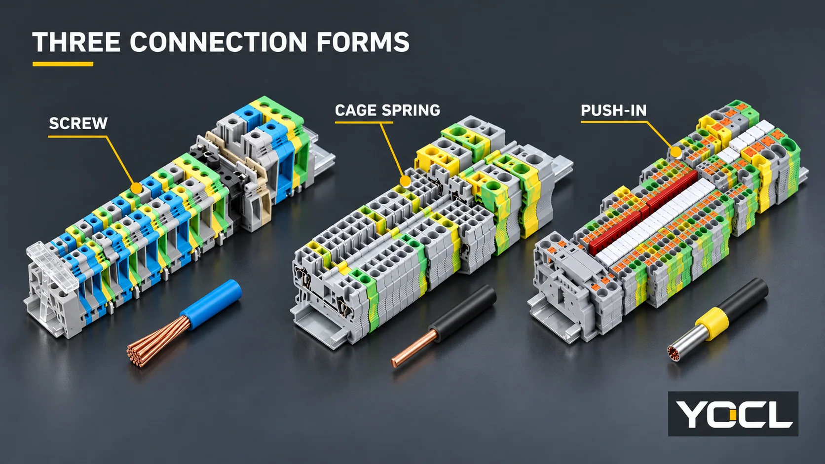
A screw terminal transfers clamping force through the screw and clamp system. Start with the approved tightening method and value for the exact terminal. If either is unavailable, obtain them before returning the assembly to service; do not copy a torque value from another terminal family or another product’s instruction.
After isolation, the qualified inspector should look for a screw that does not retain the specified clamping condition, a clamp that has shifted, a conductor positioned outside the intended contact area, a stripped or damaged screw, and a conductor that moves although the clamp has been assembled. A screw that requires repeated re-tightening is evidence of a condition to investigate, not proof that routine re-tightening is an appropriate maintenance strategy.
The screw versus spring terminal comparison explains the wider workflow difference between these clamp types.
Cage-spring and push-in terminals
Spring terminals do not use a screw torque setting to create the same clamp action, but they still have exact conductor, preparation, insertion and release requirements. Check that the conductor reached the specified insertion depth, that the correct entry was used, that the spring and entry show no visible damage or deformation, and that the conductor is retained under the intended clamp.
Push-in operation can look deceptively simple. Confirm that the exact model accepts the conductor construction and prepared end, and follow the printed strip length. “Push-in” is also used broadly in product literature, so identify whether the entry has a direct-insertion design or another spring operation. The YOCL PT push-in series dan SJ spring series are examples of products that must be read as distinct exact-model records.
Conductor preparation and conductor count
Inspect the prepared end against the model’s approved preparation. For stranded or fine-stranded wire, a wire ferrule may be required by the product or wiring specification, but its presence does not prove the assembled connection is correct. Check the ferrule dimensions and the terminal’s printed conductor information separately.
Common evidence to record includes:
- The conductor material, construction and cross-section that is actually installed.
- The finished prepared end, including any ferrule, sleeve or other termination.
- The printed strip length and the amount of conductor visible after assembly.
- The number of conductors in one clamping point and whether each entered the intended current-carrying area.
- Whether strands, insulation or a ferrule collar sit where the product requires the metal conductor.
- Whether the same fault recurs only after a cable is moved, a cover is closed or a bridge is fitted.
A conductor that fits into the opening is not automatically an accepted combination. The exact model and the completed connection must both be checked.
Treat a bridge or accessory as another current path
A terminal row can look like several independent circuits when a jumper or comb busbar connects them. Electrically, the accessory can create one path that carries the aggregated current before it divides into branches. That path needs its own model identification, current data, insulation or cover arrangement and installation orientation.
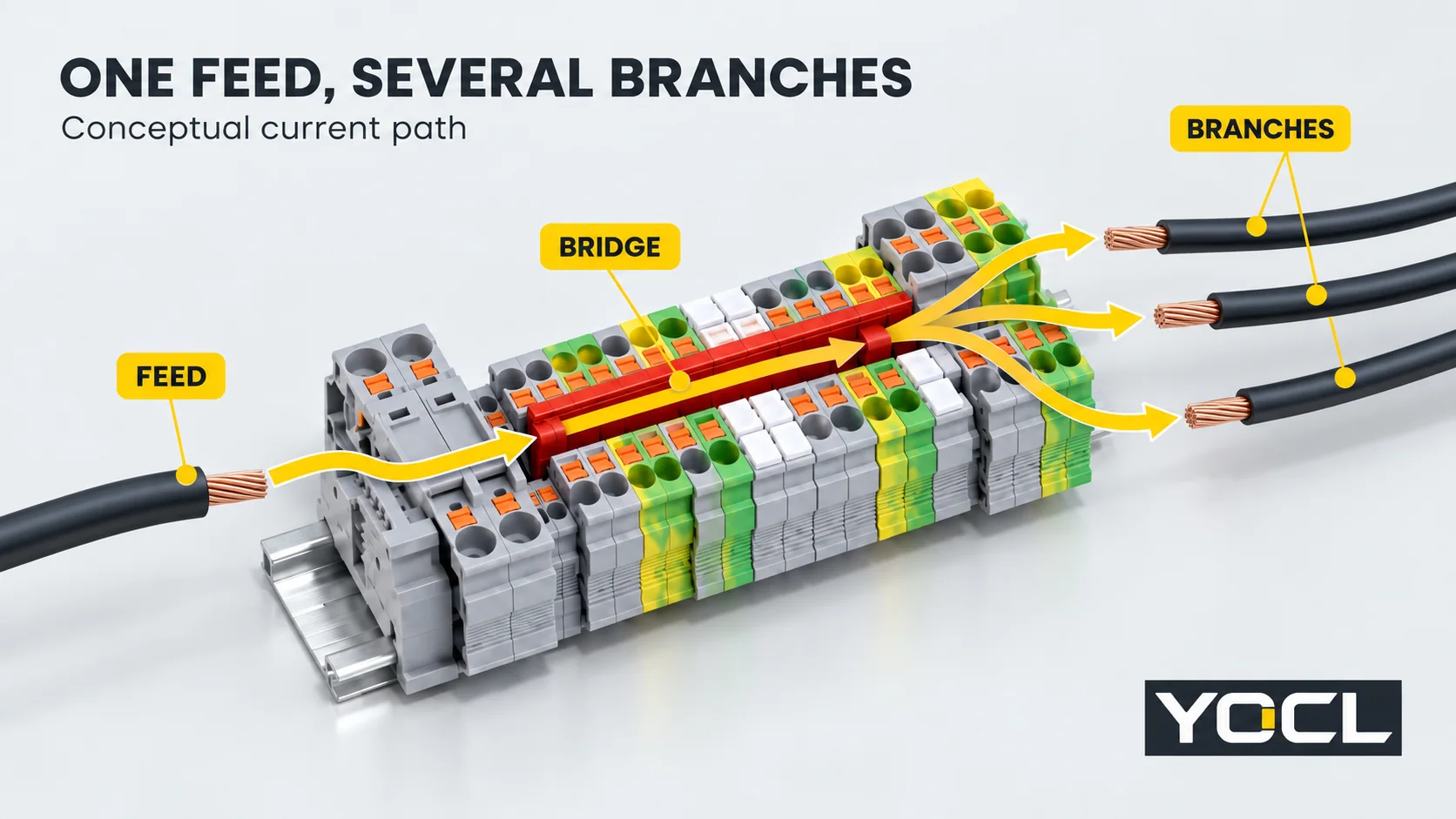
Use the following checks after isolation:
- Identify the exact bridge or jumper and its approved number of poles or connection positions.
- Confirm that it is installed on the terminal models intended to receive it.
- Compare the shared feed current and branch arrangement with the accessory’s exact limits.
- Check for an interrupted, partly seated or incorrect-position accessory that can concentrate current in fewer paths.
- Check whether covers, end stops or insulating parts are present in the specified arrangement.
- Preserve the original bridge position and connection sequence before removing it.
The YOCL comb busbar guide covers the wider role of these accessories, while the pin versus fork comb busbar comparison helps identify the contact format. For the bridge issue itself, the decisive evidence is the exact accessory and terminal combination, not the appearance of an intact plastic cover.
If an accessory is missing its rating or installation information, escalate that gap. Do not infer a current limit from the number of visible pins or from the colour of the plastic.
Check the thermal environment and installation arrangement
The same terminal and current can heat differently in two enclosures. Look beyond the terminal for conditions that reduce heat removal or add external heat:
- The measured ambient temperature and its variation through the working cycle.
- Heat-producing equipment immediately beside or below the terminal row.
- Enclosed spaces, blocked ventilation routes and heat trapped under covers.
- Dense rows, stacked terminal levels or barriers that alter the installation arrangement.
- Insufficient conductor and bending space that strains the connection or blocks access.
- Solar loading, process heat and external equipment surfaces where relevant.
The TS35 DIN rail dimensions guide separates rail profile dimensions from device fit. Correct rail size alone does not establish that the terminal has adequate space, conductor access or thermal conditions.
If heat reduces after a temporary external source is removed, record what changed and verify the result after the system returns to its approved operating condition. A fan added during fault finding is not evidence that the installed thermal design is adequate.
Recognise when replacement or escalation is the right decision
Some evidence changes the decision from “investigate the connection” to “do not reuse the affected assembly without approval.”
| Kondisi | Safe decision boundary |
|---|---|
| Discolouration, charring, melted polymer, cracks, deformation, broken insulation or arcing marks | Isolate and replace the affected parts under the approved method; investigate the current path and surrounding damage before reuse |
| Repeated overheating after a documented correction | Escalate; the original diagnosis is incomplete or another cause remains |
| Repeated loosening or a clamp that no longer retains its specified condition | Remove the suspect terminal from service and obtain a replacement/selection assessment |
| Current or accessory loading outside the exact permitted conditions | Correct the circuit or product arrangement before returning to service |
| Missing torque, preparation, bridge-rating or installation information | Keep the circuit out of fault-repair scope until the required evidence is obtained |
| No identified cause after the safe checks | Escalate to the equipment manufacturer or a qualified electrical engineer rather than returning the circuit to service by assumption |
Replace like-for-like only when the original model, circuit function and installation requirements match. A higher current label on a visually similar terminal is not automatically a safe upgrade: its dimensions, conductor system, accessories, spacing and approvals may differ.
Build a record that another person can reproduce
A useful fault record makes the evidence comparable after the circuit has been isolated, cleaned or reassembled.
| Bidang catatan | Example entry |
|---|---|
| Equipment and circuit | Panel identifier, load name, terminal row and circuit number |
| Exact terminal and accessory | Manufacturer, series and model as marked; bridge/jumper and end-stop models |
| Original evidence | Photographs, local hot area, discolouration, odour, load state and observed timing |
| Electrical comparison | Recorded current or duty evidence and the exact model’s permitted conditions, with measurement method |
| Connection evidence | Conductor type, cross-section, prepared end, strip result, conductor count, clamping method and specified values |
| Thermal environment | Ambient, adjacent heat sources, enclosure arrangement, ventilation and changes during the test |
| Action and result | Part replaced, connection remade or load changed; repeat observation under the approved service condition |
| Escalation | Person or organization responsible and the evidence still missing |
Keep the record factual. “Terminal was loose” is weaker than “clamp did not retain the conductor under the specified check” or “conductor entered outside the intended clamp area.” The latter descriptions preserve what was observed and avoid claiming a cause prematurely.
Choose the next action from the evidence
Use the evidence in this order:
- Unsafe presentation: isolate, verify de-energized, preserve evidence and replace damaged components. Do not restore service after cleaning alone.
- Load above the exact permitted conditions: correct the circuit demand or product selection before further operation.
- Normal electrical system but a local hotspot: inspect clamping, conductor preparation, conductor count and accessory routing using the exact product instruction.
- Heat concentrated around a bridge or jumper: verify the shared current path and accessory arrangement as a system.
- No local connection defect but a hotter installation than a comparable panel: investigate ambient, enclosure, adjacent sources and mounting arrangement.
- No reliable cause or missing essential data: escalate. A terminal that has cooled is not evidence that the fault has been resolved.
For a new-build selection based on the findings, the DIN-rail terminal selection guide starts from conductor and circuit requirements. The panduan blok terminal explains the broader product roles, and YOCL’s DIN-rail terminal range provides the family overview.
When requesting technical support, send the completed evidence record, the exact model markings, the original connection arrangement and photographs of the affected area. Do not include a recommended torque, current or replacement model unless it is supported by the exact product documentation for the assembly.
Referensi
- Health and Safety Executive, Pendahuluan keselamatan kelistrikan, including signs of equipment deterioration and overheating.
- International Electrotechnical Commission, IEC 60947-7-1:2025 publication record, including the public preview and limited scope/test context used here.
- UL Standards & Engagement, UL 1059, Terminal Blocks, including the public scope statement concerning terminal-block use in end products.
- Solusi UL, Plastic materials testing, explaining ignition and arcing risks associated with overloaded or loose electrical connections.
- YOCL ELECTRIC, UK series screw DIN-rail terminal blocks, product information for the UK-10RD fields cited.
- YOCL ELECTRIC, SJ terminal blocks, product information for the SJ-2.5 fields cited.
- YOCL ELECTRIC, PT series push-in DIN-rail terminal blocks, product information for the PT2.5 fields cited.