
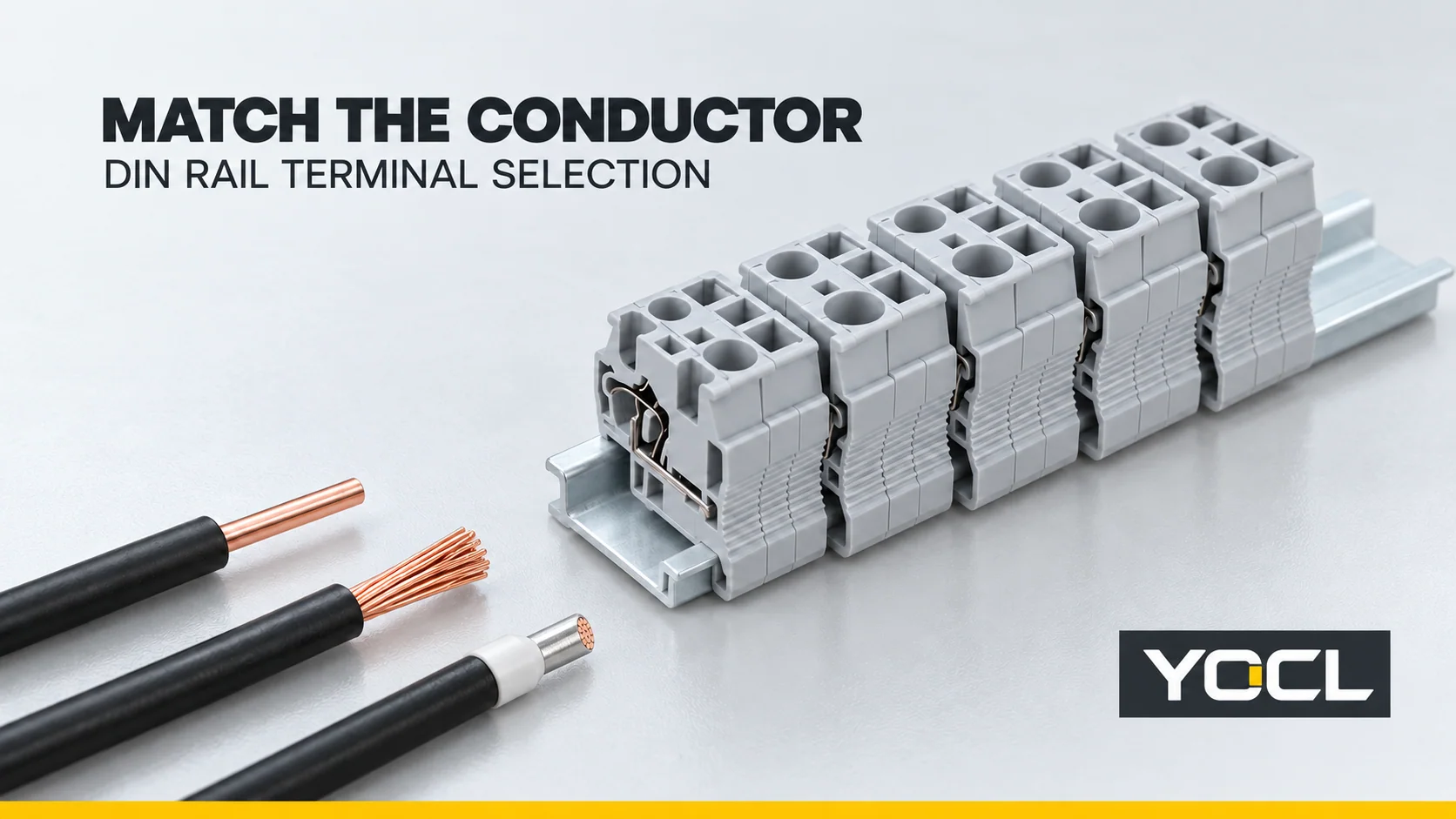
Start with the conductor’s material, construction, cross-section, prepared end and number of wires per clamping point. Match those inputs to the exact terminal’s connection-capacity data, then check circuit ratings, function and mounting. A model marked 2.5 mm² does not necessarily accept every 2.5 mm² wire preparation, and its maximum rigid-wire size may exceed its flexible-wire limit.
Good DIN rail terminal block selection produces a documented part number and accessory list. It also identifies what still needs confirmation. A conductor that fits the opening has passed only a physical check; the terminal must be intended for that conductor and the application.
Build the conductor record before choosing the clamp
Record these inputs for each connection point, including both sides of a feed-through terminal:
- Conductor material: copper, aluminium or another specified material. Do not assume that a terminal intended for copper also accepts aluminium.
- Construction: solid, stranded or fine-stranded, using the cable manufacturer’s designation or strand class where available. Record the actual construction rather than translating every stranded wire into a generic label.
- Cross-section: the declared mm² or American Wire Gauge (AWG) size. When the terminal provides an AWG range, use that range directly; a rounded unit conversion does not establish acceptance.
- Prepared end: bare stripped conductor, ferrule without an insulating collar, ferrule with a collar, or a twin ferrule. For ferrules, record the sleeve length and finished profile as well as nominal conductor size.
- Conductor count: one wire or a specifically permitted multi-conductor arrangement in each clamp. Two entry positions and two wires in one entry are different configurations.
The scope of IEC 60947-7-1:2025 covers industrial support-mounted terminal blocks for round copper conductors, including conductors with special preparation. That broad scope does not tell you the capacity of an individual terminal. The model’s declared connection data must complete the conductor record.
If you are still identifying the required terminal form or circuit configuration, start with what a terminal block is. Once the conductor is known, compare the available connection methods. The screw-versus-spring terminal-block guide covers their wiring and maintenance tradeoffs; here, the task is to establish which exact part accepts your connection.
| Selection input | Find this in the exact terminal documentation | Decision it supports |
|---|---|---|
| Wire material, construction and size | The matching conductor-type and cross-section range | Reject a terminal outside the applicable range |
| Bare or ferruled end | Preparation-specific capacity, insertion requirements and compatible end dimensions | Establish whether the proposed prepared end is accepted |
| Wires per clamping point | Permitted conductor count and combinations | Distinguish one-wire, separate-entry and approved shared-clamp arrangements |
| Circuit duty and installation environment | Applicable current, voltage, temperature and certification conditions | Check the candidate in the intended equipment |
| Fungsi koneksi | Circuit diagram and feed-through, protective-earth, disconnect or fuse configuration | Select the function the schematic requires |
| Rail and assembly space | Mounting profile, dimensions, access and compatible accessories | Complete the terminal-system specification |
Read connecting capacity separately from nominal size
A rated or nominal cross-section is not a full list of accepted conductors. Read the minimum and maximum values for the actual wire construction and preparation. The same model can have different rigid, flexible and ferruled capacities. A range for one preparation cannot fill a missing row for another.
milik YOCL SJ cage-spring terminal-block table makes this distinction visible. It lists separate rigid and flexible wire ranges:
| YOCL model | Luas penampang terukur | Declared rigid-wire range | Declared flexible-wire range | First filter for a 4 mm² flexible conductor |
|---|---|---|---|---|
| SJ-2.5 | 2.5 mm² | 0.2–4 mm² | 0.2–2.5 mm² | Reject: the flexible conductor exceeds the declared range |
| SJ-4 | 4 mm² | 0.2–6 mm² | 0.2–4 mm² | Candidate: it passes this flexible-range check |
Ini adalah YOCL catalogue declarations, not results from an independent comparison test. The input is a hypothetical 4 mm² flexible conductor. SJ-2.5 fails that check even though its rigid range reaches 4 mm². SJ-4 passes the range filter; its end preparation, conductor count, electrical conditions and mounting still need confirmation.
The SJ table does not separately declare bare-versus-ferruled or twin-ferrule ranges. If the 4 mm² wire will carry a ferrule, the flexible range alone does not approve that prepared end. Request the applicable capacity and preparation instructions.
Read other series just as carefully. In the YOCL PT push-in table, the PT2.5 entry identifies 2.5 mm² as its rated cross-section. That single value is not a complete minimum-to-maximum connecting range. Do not copy SJ ranges into PT2.5, or borrow another manufacturer’s data because a model name looks similar.
Check the prepared end as well as the copper size
A ferrule changes the outer envelope presented to the clamp. Its sleeve, collar and finished crimp must fit the terminal’s permitted preparation. The receiving terminal must accept that arrangement; selecting a ferrule with the correct nominal wire size settles only one part of the connection.
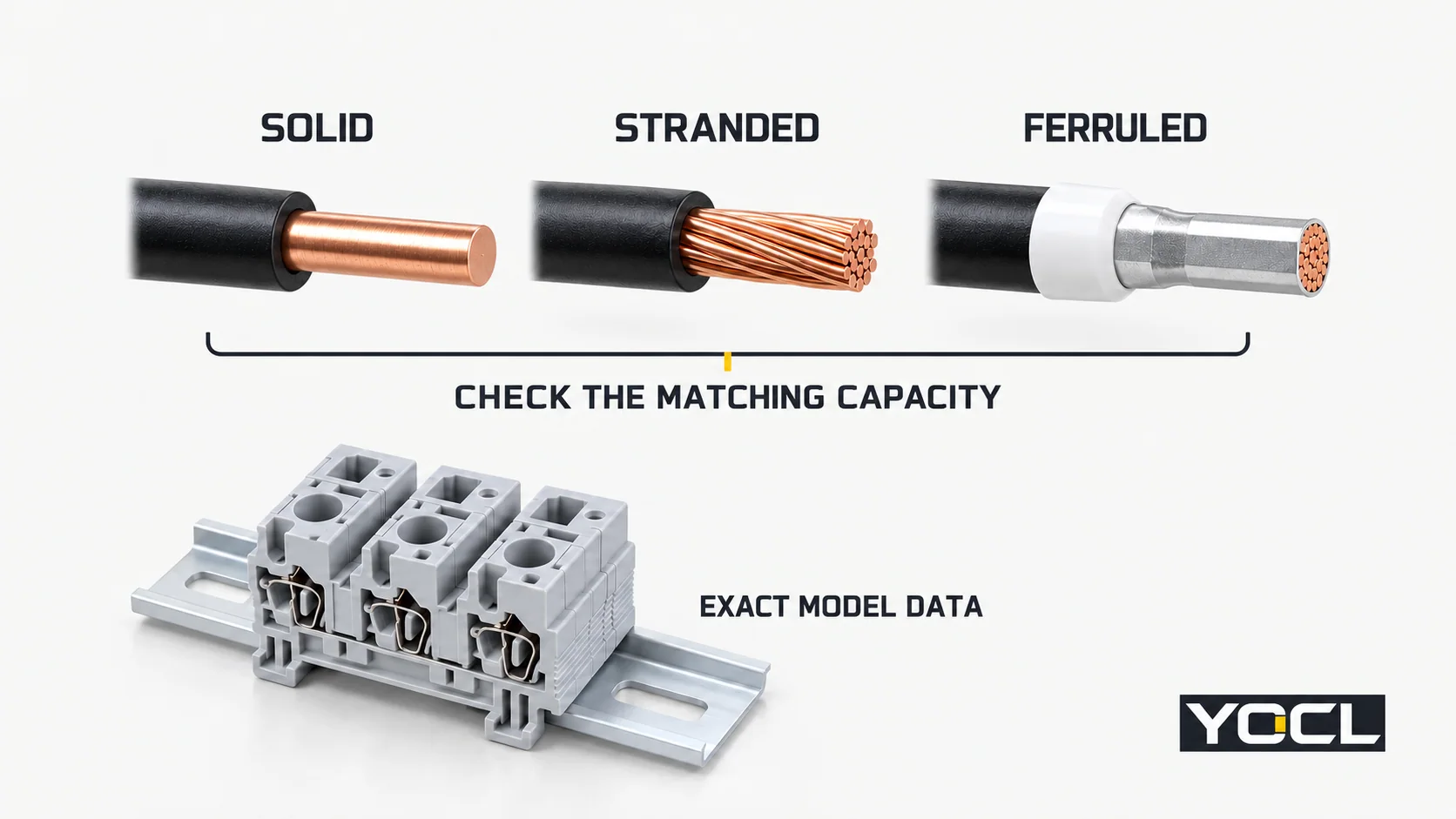
For a ferruled conductor, confirm:
- Capacity: the terminal’s accepted ferruled range for the actual wire construction and conductor count.
- Sleeve length and seating: whether the prepared end can reach the intended contact position without bottoming out or being obstructed by its collar.
- Finished envelope: whether the specified crimp shape and dimensions enter without forcing or deforming the end.
- Preparation method: the ferrule and tooling instructions, followed by the terminal’s insertion and clamping instructions.
The bagan ukuran ferrule kawat helps identify conductor size and sleeve length. It does not replace the receiving terminal’s compatibility data. Similarly, a ferrule’s own standard does not approve every receiving clamp. The public scope of UL 486F defines particular conductor and connection-device applications; it is not a universal permission to use any ferrule in any terminal.
The same distinction matters for push-in designs. YOCL’s PT range describes direct insertion of suitable solid conductors or conductors fitted with ferrules. That series-level description does not establish direct insertion of every bare fine-stranded conductor. Check the exact model’s permitted preparation and operating method.
Two wires need their own acceptance check
Two 1.5 mm² conductors do not automatically become a permitted connection because their combined nominal area is 3 mm². Two bare wires, two individually ferruled wires and one twin ferrule present different arrangements to the clamp.
Look for an explicit conductor-count and preparation declaration. Names such as TWIN or QUATTRO can describe extra connection positions in a terminal family; they do not establish permission for multiple wires in one clamp. The single-versus-twin ferrule comparison explains the prepared-end distinction. If the terminal documentation does not resolve the proposed arrangement, keep that candidate unconfirmed.
Match the circuit conditions within one approval framework
Conductor acceptance and electrical suitability are separate checks. Record the circuit’s required current and operating voltage, the equipment’s insulation requirements, ambient conditions and intended certification framework. Compare them with the exact model’s applicable ratings and use conditions.
Avoid combining an IEC catalogue voltage, a UL wire range and a current figure from a different configuration into one specification. Keep the ratings and their conditions together. A terminal’s capacity to accept a larger conductor does not provide a new current rating, and the terminal’s headline current does not determine the cable’s permissible load.
For a U.S. industrial control panel evaluated under UL 508A, the UL Solutions Supplement SA directs component checks to matters including wire size, intended use, electrical ratings and applicable Conditions of Acceptability. For internal wiring, its conductor provisions also distinguish constructions beyond ordinary Class B/C stranding. This is a specific panel context: obtain the relevant record and instructions for the proposed component and wire.
Cakupan publik dari UL 1059 also distinguishes terminal-block compliance from suitability in the finished equipment. A generic standards reference or catalogue logo cannot establish that a particular YOCL part is approved for your project. Request the exact documentation when certification is part of the specification.
Next, match the schematic function. A feed-through terminal, protective-earth terminal, disconnect terminal and fuse terminal have different jobs. Select the required configuration before finalizing bridges or other circuit accessories. An ordinary feed-through block sharing a rail does not acquire a protective-earth function.
Verify rail fit, space and the accessory list
Confirm the rail profile stated for the selected model. YOCL declares TH35-7.5 or TH35-15 mounting for the SJ range. Use the TS35 DIN rail dimensions guide when checking the rail drawing, but establish the terminal’s mounting compatibility from its own data.
Rail compatibility is a mechanical check. The abstract of IEC 60715:2017 separates mechanical rail mounting from the protective-earthing function addressed by the relevant product standard. A shared rail therefore does not prove electrical interchangeability or a protective-earth connection.
Check the complete row within the enclosure: terminal widths and quantities, end plates where required, end stops, partitions, marking and bridge positions. Allow the access and clearance needed by the specified wiring method and enclosure arrangement. A block may fit on the rail while its wire entry or tool access is obstructed by the cable duct.
Use model-compatible bridges, covers and stops. A bridge is an electrical component with its own applicable arrangement and rating; an end plate and an end stop serve different purposes. The hub explains those roles. The selection task is to record the correct part numbers and verify them against the chosen terminal series.
Obtain the model’s installation instructions with the selection documents. Screw size is not tightening torque, and housing height is not strip length. Missing values should be requested from the supplier rather than estimated from appearance or transferred from another terminal.
Finish with a terminal schedule the supplier can verify
Use rejected, candidate dan specified as distinct outcomes. Reject a model that fails an applicable requirement. Keep it as a candidate while required evidence is missing. Specify it once the documented conductor arrangement and remaining application checks are resolved.
For the 4 mm² flexible-conductor example, the selection record would start like this:
| Schedule field | Entry or evidence required |
|---|---|
| Konduktor | Actual cable part number, copper construction/strand class and 4 mm² nominal area; record the wire at every connection point |
| End preparation and count | Bare or exact ferrule part, sleeve length and crimp details; number of wires per clamp |
| Range decision | SJ-2.5 rejected on flexible range; SJ-4 remains a candidate after that check |
| Remaining connection evidence | Accepted preparation/count, insertion requirements and applicable model instructions |
| Circuit and approval | Required current, voltage, ambient conditions and target-market documentation; confirm applicable part ratings |
| Function and assembly | Feed-through or other required function; rail profile, quantity, layout and compatible accessory part numbers |
Do not turn the range result into a completed order while the other fields are blank.
Example enquiry — hypothetical input: “Please propose a DIN-rail feed-through terminal for one 4 mm² flexible copper conductor per clamping point. The cable part number, strand class, end preparation, circuit current/voltage, enclosure conditions and rail drawing will be supplied in the terminal schedule. Confirm the exact model’s relevant conductor capacity, permitted preparation, installation instructions, applicable electrical ratings and required accessories. Identify any unsupported or missing input before confirming the part.”
Send that schedule when reviewing YOCL terminal blocks. It gives the supplier a defined connection to check and gives the panel designer a record of why the selected part fits the application.
Referensi
- International Electrotechnical Commission, IEC 60947-7-1:2025 — Terminal blocks for copper conductors, edition 4; public scope and publication metadata.
- YOCL ELECTRIC, Blok Terminal Rel Pegas Sangkar SJ DIN, YOCL product information; SJ-2.5/SJ-4 conductor ranges and declared mounting.
- YOCL ELECTRIC, Blok Terminal Rel Push-In Seri PT DIN, YOCL product information; rated-cross-section note and series-level preparation description.
- UL Standards & Engagement, UL 486F — Bare and Covered Ferrules, edition 3, revised August 28, 2026; public scope only.
- Solusi UL, UL 508A Supplement SA — Specific Component Requirements, linked October 28, 2025 PDF; sections 2.3/2.6 and table entries 28.2.1/29.2.1.
- UL Standards & Engagement, UL 1059 — Terminal Blocks, edition 6, December 11, 2024; public scope only.
- International Electrotechnical Commission, IEC 60715:2017 — Standardized mounting on rails for mechanical support, edition 2; public scope and protective-earthing boundary.