
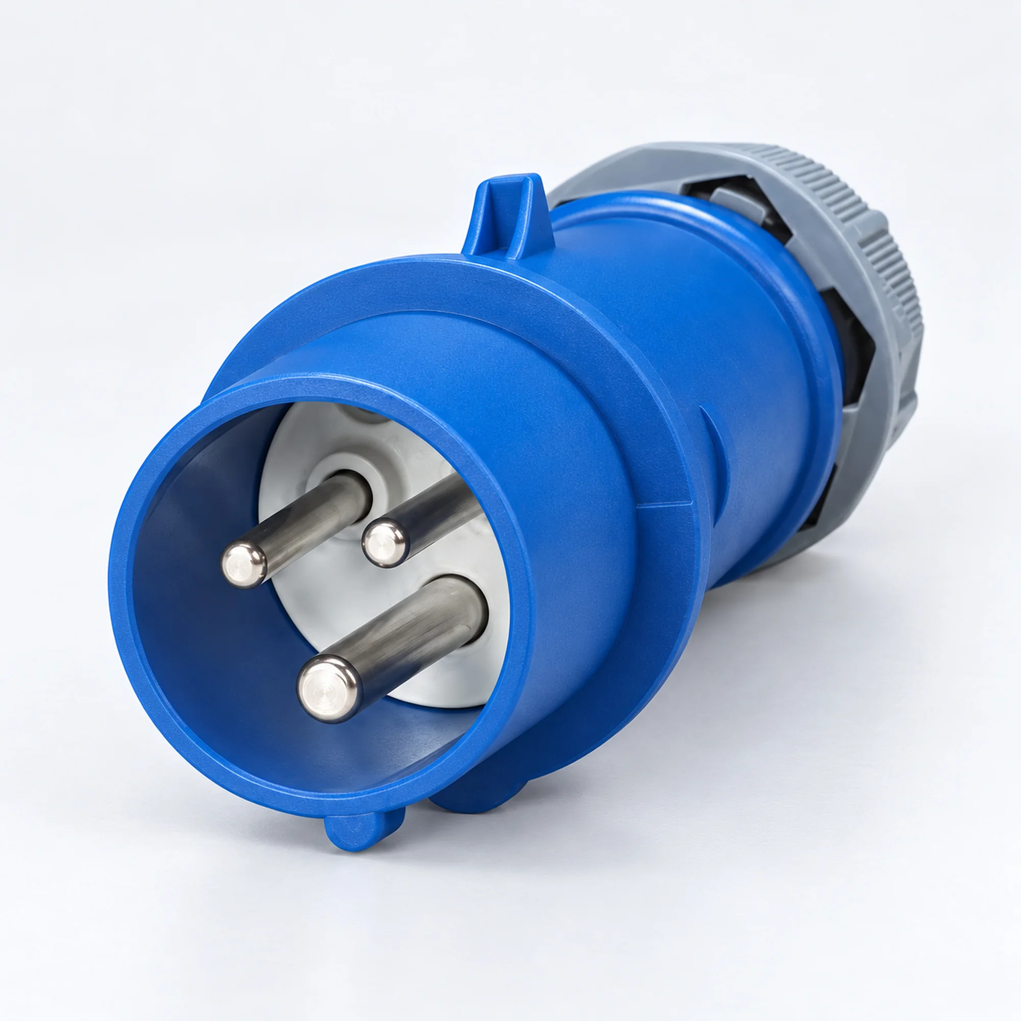
IP44 Industriestecker
YOCL ELECTRIC IP44 Industriestecker für Kabelendverbindungen, mit unterschiedlichen Gehäusedesigns und vollständigen NM-Modellauswahltabellen.
- Nennströme: 16 A und 32 A.
- Kontaktbelegungen: 2P+E, 3P+E und 3P+N+E.
- 4h, 6h und ausgewählte 9h Schutzkontakt-Anordnungen, je nach Modell.
- Steckertyp mit hinterem Kabeleingang.
- Spannung, Leiterkapazität und Abmessungen anhand des vollständigen Modellcodes auswählen.
Übersicht
YOCL ELECTRIC IP44 Industriestecker sind Stecker für industrielle Kabelverbindungen. Diese Familie vereint die tatsächlichen 16 A und 32 A Modelle, die unten aufgeführt sind, mit 2P+E, 3P+E und 3P+N+E Kontaktanordnungen. Jedes Modell hat seine eigene Spannung, seine eigene Schutzkontakt-Uhrposition und sein eigenes Gehäusedesign.
Die Vorderseite hat vorstehende männliche Kontakte und die Rückseite nimmt ein Kabel auf. H-Design, K-Design und weiße Rückseitenversionen bieten unterschiedliche Gehäuse innerhalb einer Produktfamilie. Die speziellen 9h-Versionen sind getrennt von gewöhnlichen 4h- und 6h-Modellen aufgeführt.
Merkmale
- IP44 Schutzart für die aufgeführten Modelle.
- Männliche Kontakte mit Kabelmontage statt Schalttafeleinbau.
- Nennstromoptionen: 16 A und 32 A; die tatsächlichen Kombinationen sind durch die Modelltabellen definiert.
- 2P+E, 3P+E und 3P+N+E Versionen werden einzeln identifiziert.
- Schutzkontakt-Layouts: 4h, 6h und ausgewählte 9h, gemäß dem genannten Modell.
- Separate Gehäusegruppen erhalten die Leiterkapazität und die Maßdaten jedes Modells.
Technische Daten
| Parameter | Spezifikation |
|---|---|
| Marke | YOCL ELEKTRO |
| Produkttyp | Steckverbinder für Kabelmontage |
| Montage | Kabelmontage |
| Schutzart | IP44 |
| Bemessungsströme | 16 A und 32 A |
| Kontaktbelegungen | 2P+E (3 Kontakte); 3P+E (4 Kontakte); 3P+N+E (5 Kontakte) |
| Erdkontaktstellungen | 4h, 6h und ausgewählte 9h |
| Spannungskonfigurationen | Siehe die einzelnen Modellzeilen; gepaarte Fünf-Kontakt-Nennwerte bleiben wie angegeben erhalten. |
| Leiterquerschnitte | Model-specific values in mm²; see the selection tables. |
| Housing designs | See the separate model groups below. |
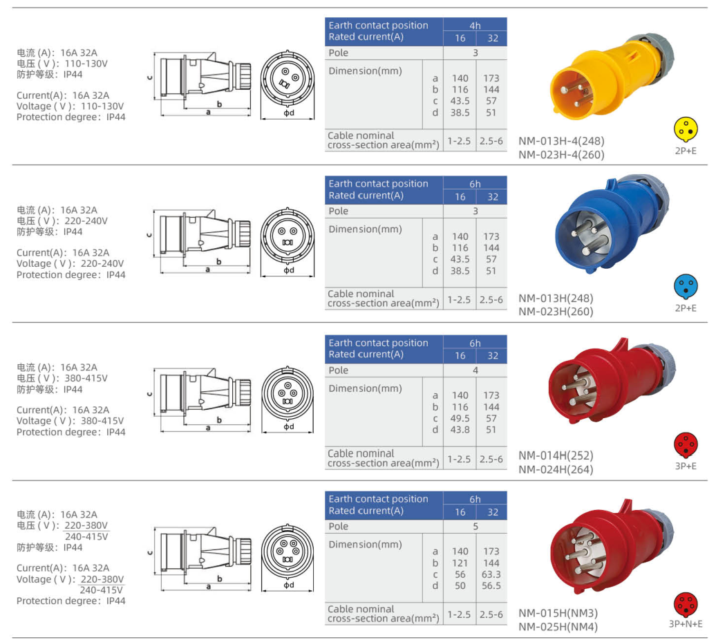
Gehäusedesign H — 16 / 32 A
| Modell | Printed reference | Strom (A) | Kontakte | Spannung (V) | Clock | Conductor capacity (mm²) | Body color |
|---|---|---|---|---|---|---|---|
| NM-013H-4 | 248 | 16 | 2P+E | 110–130 | 4h | 1–2.5 | Gelb |
| NM-023H-4 | 260 | 32 | 2P+E | 110–130 | 4h | 2.5–6 | Gelb |
| NM-013H | 248 | 16 | 2P+E | 220–240 | 6h | 1–2.5 | Blau |
| NM-023H | 260 | 32 | 2P+E | 220–240 | 6h | 2.5–6 | Blau |
| NM-014H | 252 | 16 | 3P+E | 380–415 | 6h | 1–2.5 | Rot |
| NM-024H | 264 | 32 | 3P+E | 380–415 | 6h | 2.5–6 | Rot |
| NM-015H | NM3 | 16 | 3P+N+E | 220–380 / 240–415 | 6h | 1–2.5 | Rot |
| NM-025H | NM4 | 32 | 3P+N+E | 220–380 / 240–415 | 6h | 2.5–6 | Rot |
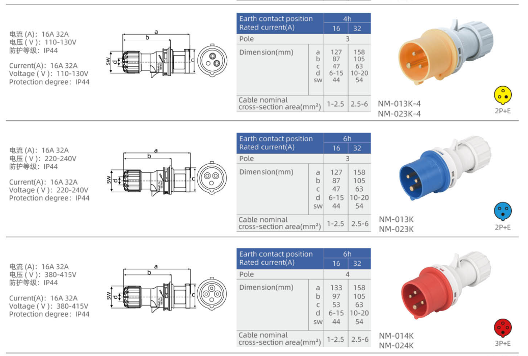
Gehäusedesign K — 16 / 32 A
| Modell | Strom (A) | Kontakte | Spannung (V) | Clock | Conductor capacity (mm²) | Body color |
|---|---|---|---|---|---|---|
| NM-013K-4 | 16 | 2P+E | 110–130 | 4h | 1–2.5 | Gelb |
| NM-023K-4 | 32 | 2P+E | 110–130 | 4h | 2.5–6 | Gelb |
| NM-013K | 16 | 2P+E | 220–240 | 6h | 1–2.5 | Blau |
| NM-023K | 32 | 2P+E | 220–240 | 6h | 2.5–6 | Blau |
| NM-014K | 16 | 3P+E | 380–415 | 6h | 1–2.5 | Rot |
| NM-024K | 32 | 3P+E | 380–415 | 6h | 2.5–6 | Rot |
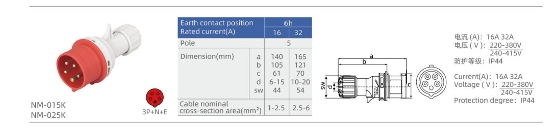
| NM-015K | 16 | 3P+N+E | 220–380 / 240–415 | 6h | 1–2.5 | Rot |
| NM-025K | 32 | 3P+N+E | 220–380 / 240–415 | 6h | 2.5–6 | Rot |
Weiße Rückseiten-Designs — 16 / 32 A
| Modell | Strom (A) | Kontakte | Spannung (V) | Clock | Conductor capacity (mm²) | Body color |
|---|---|---|---|---|---|---|
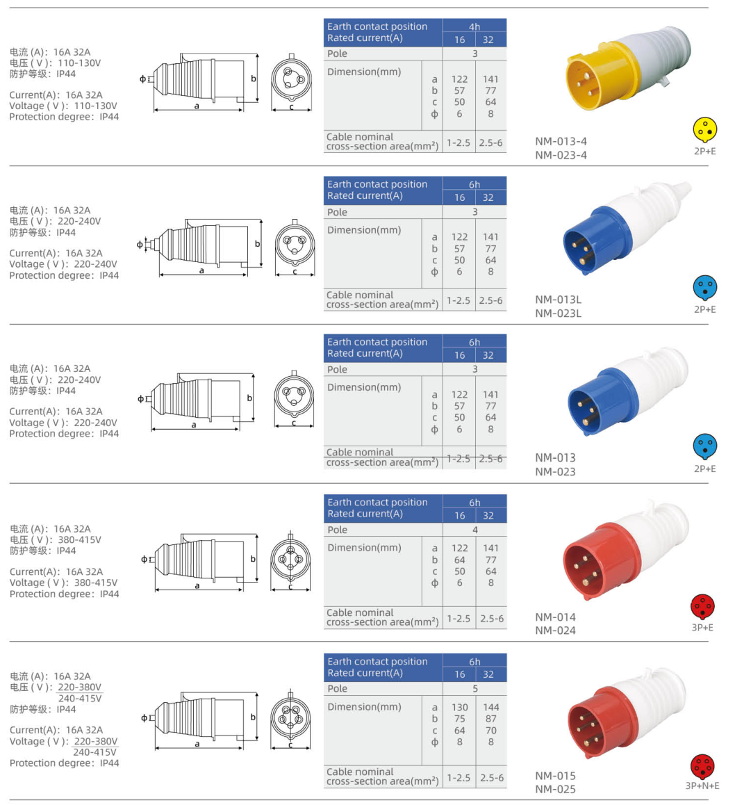
| NM-013-4 | 16 | 2P+E | 110–130 | 4h | 1–2.5 | Gelb |
| NM-023-4 | 32 | 2P+E | 110–130 | 4h | 2.5–6 | Gelb |
| NM-013L | 16 | 2P+E | 220–240 | 6h | 1–2.5 | Blau |
| NM-023L | 32 | 2P+E | 220–240 | 6h | 2.5–6 | Blau |
| NM-013 | 16 | 2P+E | 220–240 | 6h | 1–2.5 | Blau |
| NM-023 | 32 | 2P+E | 220–240 | 6h | 2.5–6 | Blau |
| NM-014 | 16 | 3P+E | 380–415 | 6h | 1–2.5 | Rot |
| NM-024 | 32 | 3P+E | 380–415 | 6h | 2.5–6 | Rot |
| NM-015 | 16 | 3P+N+E | 220–380 / 240–415 | 6h | 1–2.5 | Rot |
| NM-025 | 32 | 3P+N+E | 220–380 / 240–415 | 6h | 2.5–6 | Rot |
Spezielle 9h Kontaktanordnungen — 16 / 32 A
These 9h models use the particular voltage and contact layouts shown below. Their conductor capacities and dimensions are not extended from the ordinary models.
| Modell | Strom (A) | Kontakte | Spannung (V) | Clock | Conductor capacity (mm²) | Body color |
|---|---|---|---|---|---|---|
| NM-013L-9 | 16 | 2P+E | 380–415 | 9h | — | Rot |
| NM-023L-9 | 32 | 2P+E | 380–415 | 9h | — | Rot |
| NM-115L-9 | 16 | 3P+N+E | 220–240 | 9h | — | Blau |
| NM-025L-9 | 32 | 3P+N+E | 220–240 | 9h | — | Blau |
| NM-014L-9 | 16 | 3P+E | 220–240 | 9h | — | Blau |
| NM-024L-9 | 32 | 3P+E | 220–240 | 9h | — | Blau |
Abmessung
The symbols below reproduce each housing group’s dimensional table in millimetres. Letter meanings differ between drawings; a repeated symbol does not define one common dimension across all groups. Match the full model code and housing group before using a drawing.
Gehäusedesign H — 16 / 32 A
| Modell | Drawing/table dimensions (mm) |
|---|---|
| NM-013H-4 | a = 140; b = 116; c = 43.5; d = 38.5 |
| NM-023H-4 | a = 173; b = 144; c = 57; d = 51 |
| NM-013H | a = 140; b = 116; c = 43.5; d = 38.5 |
| NM-023H | a = 173; b = 144; c = 57; d = 51 |
| NM-014H | a = 140; b = 116; c = 49.5; d = 43.8 |
| NM-024H | a = 173; b = 144; c = 57; d = 51 |
| NM-015H | a = 140; b = 121; c = 56; d = 50 |
| NM-025H | a = 173; b = 144; c = 63.3; d = 56.5 |
Gehäusedesign K — 16 / 32 A
| Modell | Drawing/table dimensions (mm) |
|---|---|
| NM-013K-4 | a = 127; b = 87; c = 47; d = 6–15; SW = 44 |
| NM-023K-4 | a = 158; b = 105; c = 63; d = 10–20; SW = 54 |
| NM-013K | a = 127; b = 87; c = 47; d = 6–15; SW = 44 |
| NM-023K | a = 158; b = 105; c = 63; d = 10–20; SW = 54 |
| NM-014K | a = 133; b = 97; c = 53; d = 6–15; SW = 44 |
| NM-024K | a = 158; b = 105; c = 63; d = 10–20; SW = 54 |
| NM-015K | a = 140; b = 105; c = 61; d = 6–15; SW = 44 |
| NM-025K | a = 165; b = 121; c = 70; d = 10–20; SW = 54 |
Weiße Rückseiten-Designs — 16 / 32 A
| Modell | Drawing/table dimensions (mm) |
|---|---|
| NM-013-4 | a = 122; b = 57; c = 50; φ = 6 |
| NM-023-4 | a = 141; b = 77; c = 64; φ = 8 |
| NM-013L | a = 122; b = 57; c = 50; φ = 6 |
| NM-023L | a = 141; b = 77; c = 64; φ = 8 |
| NM-013 | a = 122; b = 57; c = 50; φ = 6 |
| NM-023 | a = 141; b = 77; c = 64; φ = 8 |
| NM-014 | a = 122; b = 64; c = 50; φ = 6 |
| NM-024 | a = 141; b = 77; c = 64; φ = 8 |
| NM-015 | a = 130; b = 75; c = 64; φ = 8 |
| NM-025 | a = 144; b = 87; c = 70; φ = 8 |
Auswahlhilfe
Choose a male cable plug for a cable-end connection. A panel-mounted or surface-mounted appliance inlet uses a fixed mounting arrangement and belongs to a different product family.
Select the current rating, contact arrangement, rated voltage, earth-contact clock position and IP rating together from one actual model row. Body color alone is insufficient: the special clock-position groups include different voltage/contact combinations from the ordinary groups.
Keep the complete suffix when selecting the housing version. Models that share an electrical rating may have different lengths, cable-entry dimensions or body shapes. Conductor capacity is a cross-sectional range in mm² and must not be confused with a cable-entry dimension in mm.
For five-contact models, the table preserves the paired 220–380 / 240–415 V notation. It does not create an additional arbitrary voltage combination. A dash in the capacity column means that the particular row supplies no confirmed value.
Bestellinformationen
When enquiring about YOCL ELECTRIC IP44 industrial plugs, provide the full model code, quantity, current rating, contact arrangement, rated voltage, clock position and the required housing design. Include the conductor cross-section and cable outside diameter so that the cable entry and terminal range can be checked for that specific model.
Printed secondary references identify the catalogue entries where shown; they do not create extra model options or replace the full NM model code.