
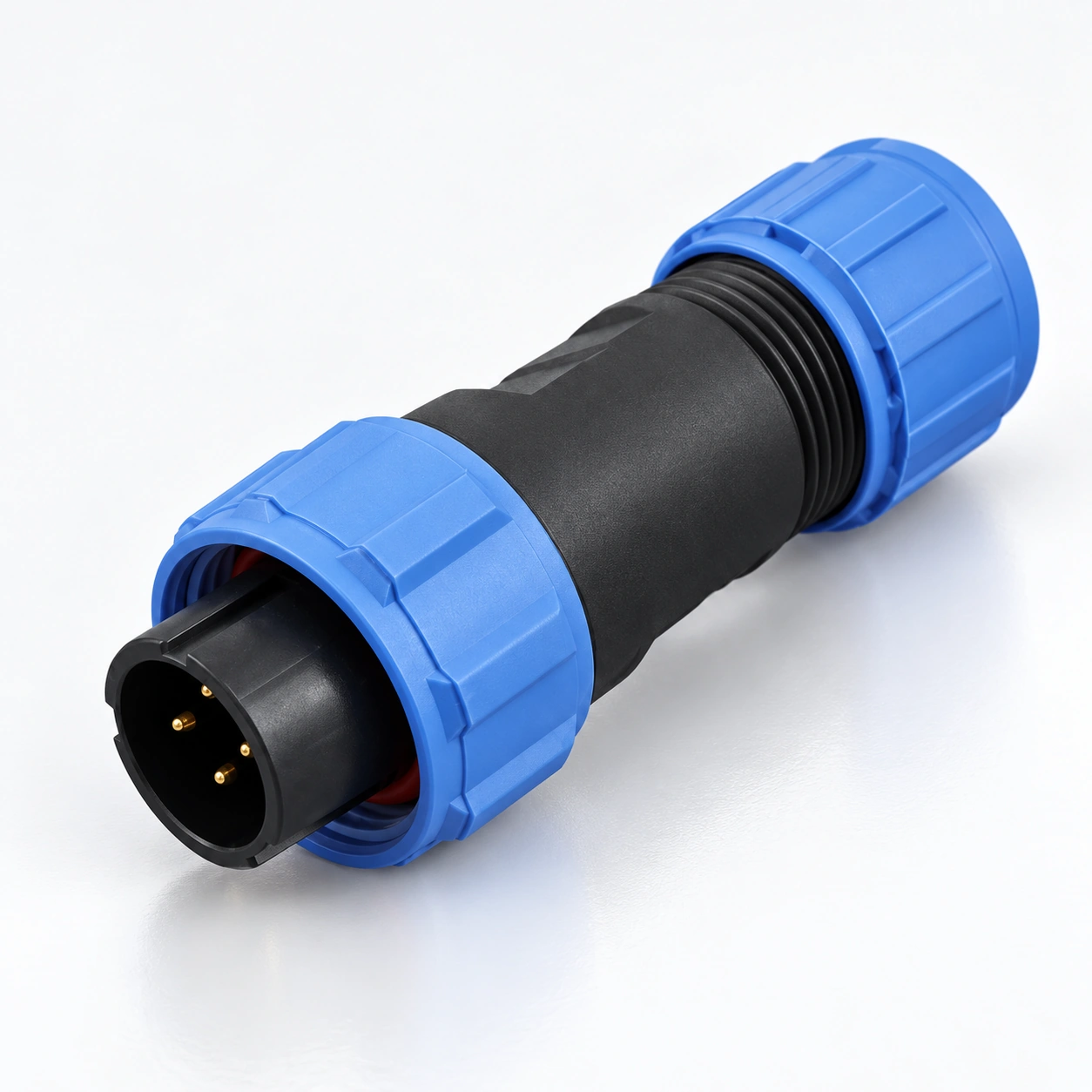
SP11 IP68 Wasserdichte Rundsteckverbinder
YOCL ELECTRIC SP11 wasserdichte Rundsteckverbinder kombinieren Gewindesicherung mit Lötanschluss für Kabel- und Panelanschlüsse.
- Kontakte: 2 / 3 / 4 / 5.
- Schutz: IP68.
- Kabeldurchmesser: 4–6.5 mm.
- Formate: Kabelstecker, Inline-Kabelbuchse, Rückmuttern-Panelbuchse und Flanschbuchse.
- Bewertungen: Wählen Sie den Strom und die AC Betriebsspannung anhand der Kontaktanzahl in der Spezifikationstabelle aus.
Übersicht
YOCL ELECTRIC SP11 wasserdichte Rundsteckverbinder bieten Gewindesicherung und Lötanschluss für abnehmbare Kabel- und Panelanschlüsse. Die Familie verwendet vergoldete Kupferkontakte, thermoplastische Gehäuse und PPS-Isolatoren mit einer IP68 Schutzart.
Die Serie umfasst vier Kontaktbelegungen: 2, 3, 4 und 5 Kontakte. Ein 45 mm Kabelstecker wird mit einer Inline-Kabelbuchse, einer Rückseiten-Panelbuchse oder einer Flanschbuchse verbunden, wodurch dieselbe Steckverbinderfamilie Kabel-zu-Kabel- und Kabel-zu-Panel-Anschlüsse bedienen kann.
Merkmale
- Gewindesicherung: Eine Schraubkupplung hält die Steckverbinderhälften zusammen.
- Kontaktoptionen: 2 / 3 / 4 / 5 Kontakte, mit elektrischen Nennwerten, die nach Kontaktbelegung ausgewählt werden.
- Vergoldete Kupferkontakte: Lötanschluss für die auf dieser Seite aufgeführten Konfigurationen.
- Kabel- und Panelformate: Kabelstecker, Inline-Kabelbuchse, Rückmuttern-Panelbuchse und Flanschbuchse.
- Kabelverschraubungsauswahl: 4–6.5 mm Kabeldurchmesser.
- Temperaturbereich: −40°C bis +85°C, mit 500 Steckzyklen für die Serie aufgeführt.
Technische Daten
Gängige Spezifikationen
| Parameter | Spezifikation |
|---|---|
| Marke | YOCL ELEKTRO |
| Serie | SP11 |
| Kontaktbelegungen | 2 / 3 / 4 / 5 Kontakte |
| Kupplung | Gewindesicherung |
| Anschluss | Löten |
| Gehäusematerial | Thermoplast PC / PA66 |
| Gehäusematerial-Brandklasse | V-0 |
| Isolationsmaterial | Thermoplast PPS |
| Kontaktmaterial | Vergoldetes Kupfer |
| Schutzart | IP68 |
| Temperaturbereich | −40°C bis +85°C |
| Steckzyklen | 500 |
| Isolationswiderstand | 2000 MΩ |
| Standard-Kabeldichtung | 4–6.5 mm |
Elektrische Nennwerte nach Kontaktanordnung
| Kontakte | Nennstrom | Betriebsspannung | Kontaktdurchmesser × Anzahl | Maximaler Leiterquerschnitt | Katalog AWG Referenz |
|---|---|---|---|---|---|
| 2 | 5 A | 180 V AC | Ø1.0 mm × 2 | ≤0.75 mm² | 18 |
| 3 | 5 A | 180 V AC | Ø1.0 mm × 3 | ≤0.75 mm² | 18 |
| 4 | 3 A | 125 V AC | Ø0.7 mm × 4 | ≤0.5 mm² | 20 |
| 5 | 5 A | 125 V AC | Ø0.7 mm × 5 | ≤0.5 mm² | 20 |
Choose the current, working voltage and conductor limit from the same row. The AWG values are the paired references supplied with the metric wire sizes; the conductor limit is expressed in mm².
Dielectric Withstand and Contact Resistance
| Kontakte | Dielektrische Spannungsfestigkeit | Kontaktwiderstand |
|---|---|---|
| 2 | 1000 V AC for 1 minute | 5 mΩ |
| 3 | 1000 V AC for 1 minute | 5 mΩ |
| 4 | 1000 V AC for 1 minute | 10 mΩ |
| 5 | 1000 V AC for 1 minute | 10 mΩ |
The dielectric withstand value is a one-minute test voltage, separate from the working voltage.
Abmessung
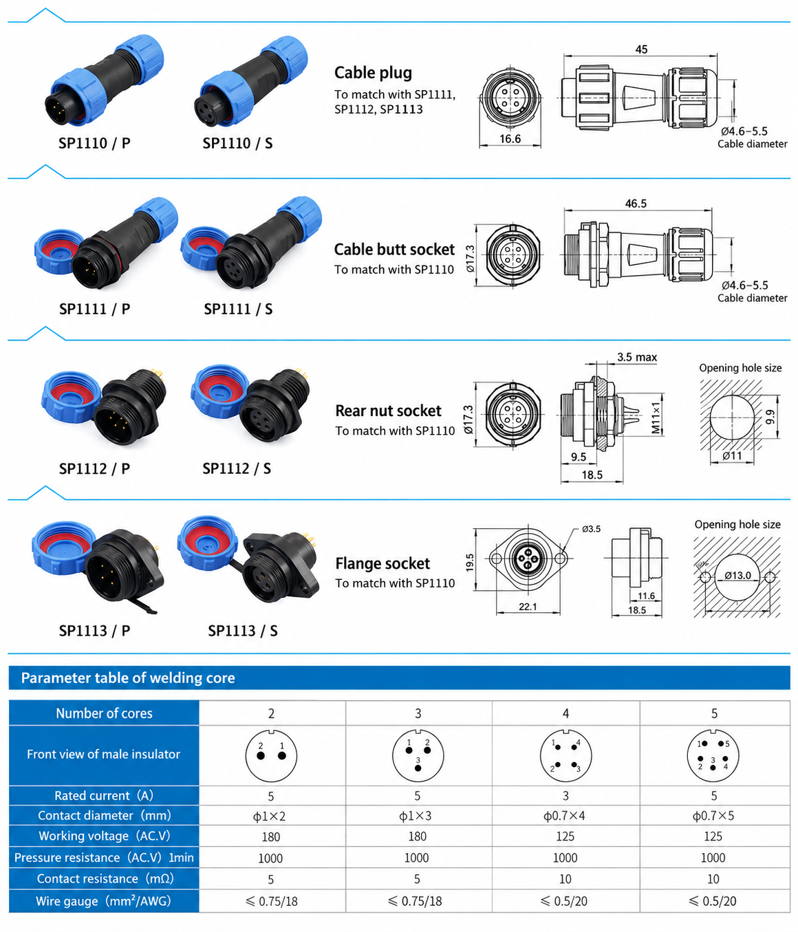
Abmessungen des Steckverbindergehäuses
| Format | Modellfamilie | Drawing dimensions |
|---|---|---|
| Kabelstecker | SP1110 | 45.0 mm length; 16.6 mm front width |
| Inline-Kabelbuchse | SP1111 | 46.5 mm length; Ø17.3 mm front diameter |
| Einbau-Buchse mit Rückseitenmutter | SP1112 | 18.5 mm length; Ø17.3 mm front diameter; M11 × 1 mounting thread |
| Flange socket | SP1113 | 18.5 mm length; 19.5 mm front height; Ø3.5 mm mounting holes; 22.1 mm body mounting-hole pitch |
Panel Mounting Dimensions
| Format | Panel opening | Montagedetails |
|---|---|---|
| Einbau-Buchse mit Rückseitenmutter | Ø11.0 mm opening with 9.9 mm across flats | Maximum panel thickness: 3.5 mm |
| Flange socket | Ø13.0 mm centre opening | Two Ø3.5 mm holes at 22.0 mm pitch |
Body dimensions and panel openings are listed separately. The flange body drawing gives 22.1 mm mounting-hole pitch, while the panel opening drawing gives 22.0 mm; use the panel opening dimensions when planning the panel.
Steckverbinderformate und Modellbezeichnungen
| Format | Pin-contact designation | Socket-contact designation | Matching format |
|---|---|---|---|
| Kabelstecker | SP1110/P | SP1110/S | Mates with SP1111, SP1112 or SP1113 of the corresponding contact arrangement |
| Inline-Kabelbuchse | SP1111/P | SP1111/S | Cable-to-cable connection with SP1110 |
| Einbau-Buchse mit Rückseitenmutter | SP1112/P | SP1112/S | Panel connection with SP1110 |
| Flange socket | SP1113/P | SP1113/S | Flange-mounted panel connection with SP1110 |
P identifies pin contacts and S identifies socket contacts. Both contact types are offered in each listed body format; choose complementary contacts and the same contact count for the mating pair. The designations above identify the connector format; specify the contact count separately in the enquiry.
Auswahlhilfe
- Select SP11 and the required contact count.
- Check the rated current, AC working voltage and conductor cross-section together in the electrical table.
- Choose a cable-to-cable or cable-to-panel connection and select the corresponding body format.
- Select the 4–6.5 mm cable seal against the actual cable outer diameter.
- Specify complementary P and S contacts and check the applicable body and panel dimensions.
Bestellinformationen
For a quotation, provide the SP11 model family, contact count, P or S contact type, cable outer diameter, mating connector format and required quantity. For panel sockets, include the panel thickness and mounting format.