
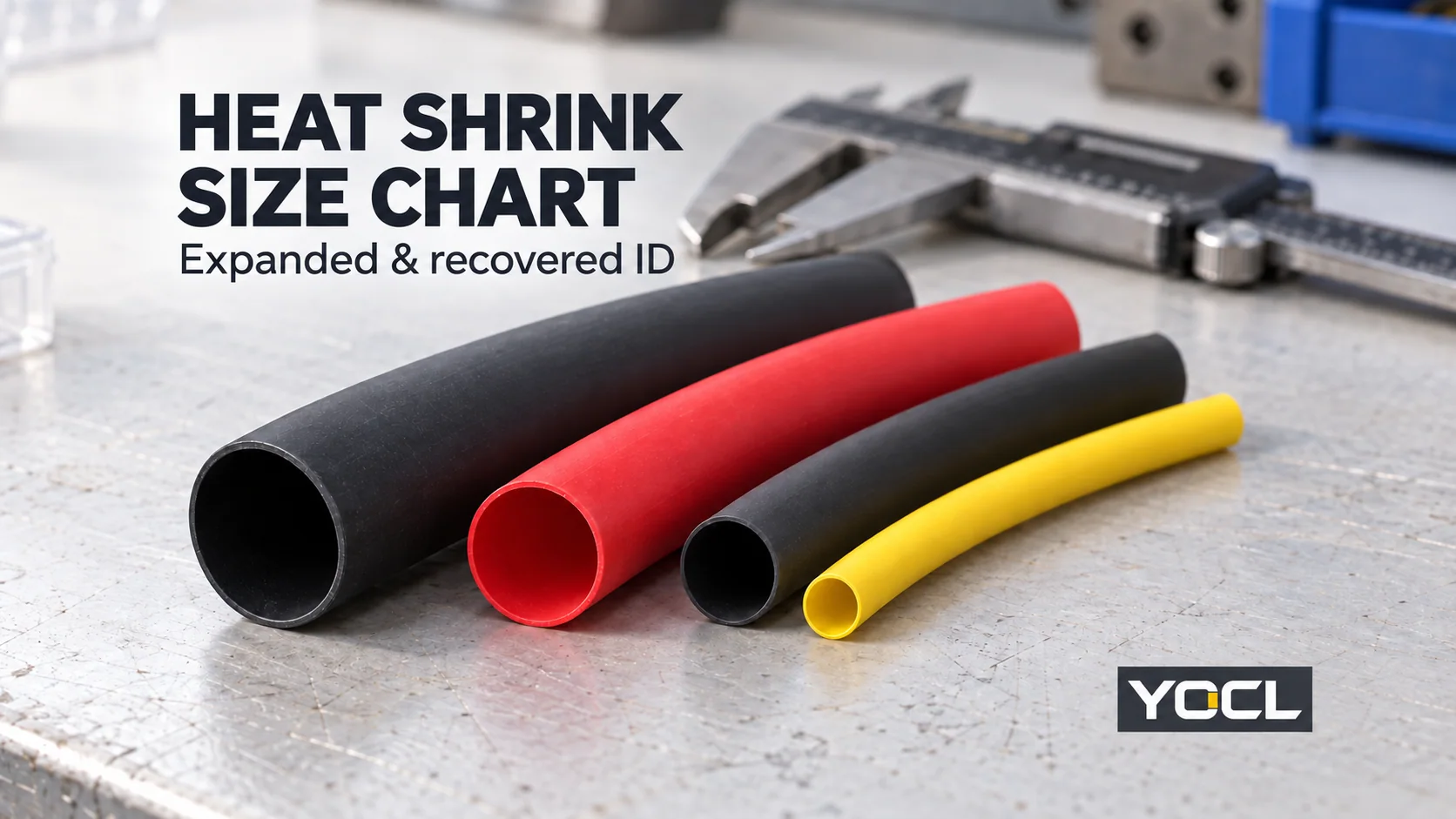
Lea una tabla de tamaños de tubo termorretráctil utilizando dos diámetros interiores: el diámetro expandido antes de calentar y el diámetro recuperado libremente después de encoger. El diámetro suministrado debe ser mayor que la característica más grande; el diámetro recuperado debe ser menor que la superficie que necesita sujetar. Utilice los límites de fila reales, en lugar de dividir un tamaño nominal por la relación de contracción.
Las tablas a continuación reproducen entradas de tamaño 61 en tres series YOCL. Todas las dimensiones están en milímetros. Son declaraciones de producto específicas de la serie, no una tabla universal para cada material termorretráctil.
YOCL tablas de tamaños de tubo termorretráctil
Aproximadamente 2:1 tubo de pared simple — HTS
La YOCL tabla de dimensiones HTS proporciona tamaños nominales emparejados y campos antes/después de encoger con tolerancias ±. Mantenga esas tolerancias al leer un tamaño como 12.0/6.0; el par no significa que ambos diámetros sean exactos.
| Par de tamaños nominales (mm) | ID antes de encoger (mm) | Campo post-encogimiento† (mm) |
|---|---|---|
| 1.0/0.5 | 1.0 ± 0.3 | 0.5 ± 0.1 |
| 1.5/0.75 | 1.5 ± 0.3 | 0.75 ± 0.1 |
| 2.0/1.0 | 2.0 ± 0.3 | 1.0 ± 0.1 |
| 2.5/1.25 | 2.5 ± 0.3 | 1.25 ± 0.1 |
| 3.0/1.5 | 3.0 ± 0.3 | 1.5 ± 0.1 |
| 3.5/1.75 | 3.5 ± 0.3 | 1.75 ± 0.1 |
| 4.0/2.0 | 4.0 ± 0.3 | 2.0 ± 0.1 |
| 5.0/2.5 | 5.0 ± 0.3 | 2.5 ± 0.2 |
| 6.0/3.0 | 6.0 ± 0.4 | 3.0 ± 0.2 |
| 7.0/3.5 | 7.0 ± 0.4 | 3.5 ± 0.2 |
| 8.0/4.0 | 8.0 ± 0.4 | 4.0 ± 0.2 |
| 9.0/4.5 | 9.0 ± 0.4 | 4.5 ± 0.2 |
| 10.0/5.0 | 10.0 ± 0.4 | 5.0 ± 0.2 |
| 11.0/5.5 | 11.0 ± 0.4 | 5.5 ± 0.2 |
| 12.0/6.0 | 12.0 ± 0.4 | 6.0 ± 0.3 |
| 13.0/6.5 | 13.0 ± 0.4 | 6.5 ± 0.3 |
| 14.0/7.0 | 14.0 ± 0.4 | 7.0 ± 0.3 |
| 15.0/7.5 | 15.0 ± 0.4 | 7.5 ± 0.4 |
| 16.0/8.0 | 16.0 ± 0.5 | 8.0 ± 0.3 |
| 17.0/8.5 | 17.0 ± 0.5 | 8.5 ± 0.3 |
| 18.0/9.0 | 18.0 ± 0.5 | 9.0 ± 0.3 |
| 20.0/10.0 | 20.0 ± 0.5 | 10.0 ± 0.3 |
| 22.0/11.0 | 22.0 ± 0.5 | 11.0 ± 0.3 |
| 25.0/12.5 | 25.0 ± 0.8 | 12.5 ± 1.0 |
| 28.0/14.0 | 28.0 ± 0.8 | 14.0 ± 1.0 |
| 30.0/15.0 | 30.0 ± 0.8 | 15.0 ± 1.0 |
| 35.0/17.5 | 35.0 ± 0.8 | 17.5 ± 1.0 |
| 40.0/20.0 | 40.0 ± 1.5 | 20.0 ± 1.0 |
| 45.0/22.5 | 45.0 ± 1.5 | 22.5 ± 1.0 |
| 50.0/25.0 | 50.0 ± 1.5 | 25.0 ± 1.0 |
| 60.0/30.0 | 60.0 ± 1.5 | 30.0 ± 1.5 |
| 70.0/35.0 | 70.0 ± 1.5 | 35.0 ± 1.5 |
| 80.0/40.0 | 80.0 ± 1.5 | 40.0 ± 1.5 |
| 90.0/45.0 | 90.0 ± 1.5 | 45.0 ± 1.5 |
| 100.0/50.0 | 100.0 ± 1.5 | 50.0 ± 1.5 |
| 120.0/60.0 | 120.0 ± 1.5 | 60.0 ± 1.5 |
| 150.0/75.0 | 150.0 ± 1.5 | 75.0 ± 1.5 |
| 180.0/90.0 | 180.0 ± 1.5 | 90.0 ± 1.5 |
| 200.0/100.0 | 200.0 ± 1.5 | 100.0 ± 1.5 |
† La fuente titula su columna posterior al encogimiento como “Máx. I.D. después de encoger” al enumerar valores ±. Dichos valores se reproducen aquí sin cambios, en lugar de reformularse como límites no cualificados. Obtenga los límites definitivos de suministro/recuperación para el tamaño HTS elegido antes de aprobar un ajuste cercano a cualquiera de los límites.
3:1 tubo con adhesivo — HS3X
La YOCL HS3X tabla de dimensiones indica un ID mínimo suministrado y ID máximo recuperado. Las entradas métricas a continuación conservan los valores publicados de YOCL; no se recalculan a partir de las etiquetas de tamaño en fracciones de pulgada.
| Tamaño métrico de entrada (mm) | ID suministrado (mm), mínimo | ID recuperado (mm), máximo |
|---|---|---|
| 2.4 | ≥2.4 | ≤0.8 |
| 3.2 | ≥3.2 | ≤1.0 |
| 4.8 | ≥4.8 | ≤1.6 |
| 6.4 | ≥6.4 | ≤2.2 |
| 7.9 | ≥7.9 | ≤2.7 |
| 9.5 | ≥9.5 | ≤3.2 |
| 12.7 | ≥12.7 | ≤4.2 |
| 15.0 | ≥15.0 | ≤5.2 |
| 19.1 | ≥19.1 | ≤6.3 |
| 25.4 | ≥25.4 | ≤8.5 |
| 30.0 | ≥30.0 | ≤10.2 |
| 39.0 | ≥39.0 | ≤13.5 |
| 50.0 | ≥50.0 | ≤17.0 |
4:1 tubo con adhesivo — HS4X
La YOCL HS4X tabla de dimensiones utiliza pares de tamaños suministrados/recuperados y límites explícitos de ≥/≤. Por ejemplo, 16.0/4.0 identifica un diámetro interior suministrado de al menos 16.0 mm y un diámetro interior recuperado de no más de 4.0 mm.
| Tamaño métrico de entrada (mm) | ID suministrado (mm), mínimo | ID recuperado (mm), máximo |
|---|---|---|
| 4.0/1.0 | ≥4.0 | ≤1.0 |
| 6.0/1.5 | ≥6.0 | ≤1.5 |
| 8.0/2.0 | ≥8.0 | ≤2.0 |
| 12.0/3.0 | ≥12.0 | ≤3.0 |
| 16.0/4.0 | ≥16.0 | ≤4.0 |
| 20.0/5.0 | ≥20.0 | ≤5.0 |
| 24.0/6.0 | ≥24.0 | ≤6.0 |
| 32.0/8.0 | ≥32.0 | ≤8.0 |
| 52.0/13.0 | ≥52.0 | ≤13.0 |
Estas tablas cubren solo HTS, HS3X y HS4X. Otros tipos de pared simple, semirrígidos, barras colectoras o grados especializados necesitan sus propias tablas de dimensiones; una relación de coincidencia no hace que sus tamaños sean intercambiables.
Los diámetros expandido, recuperado e instalado son estados diferentes
Diámetro interior (ID) mide el orificio del tubo. Diámetro exterior (OD) mide el cable o componente que debe rodear.
- Expandido/suministrado: the bore available before heating, used for the pass-over check.
- Recuperado libremente: the bore reached under specified recovery conditions without an internal object restricting contraction.
- Instalado: the sleeve conforms around the object. A cable that is larger than the free-recovery bore prevents it reaching that bore.
For the HS4X 12.0/3.0 row, the two catalogue fields are ≥12.0 mm supplied and ≤3.0 mm recovered. Neither field promises that an installed sleeve around a larger cable will have a 3.0 mm bore.
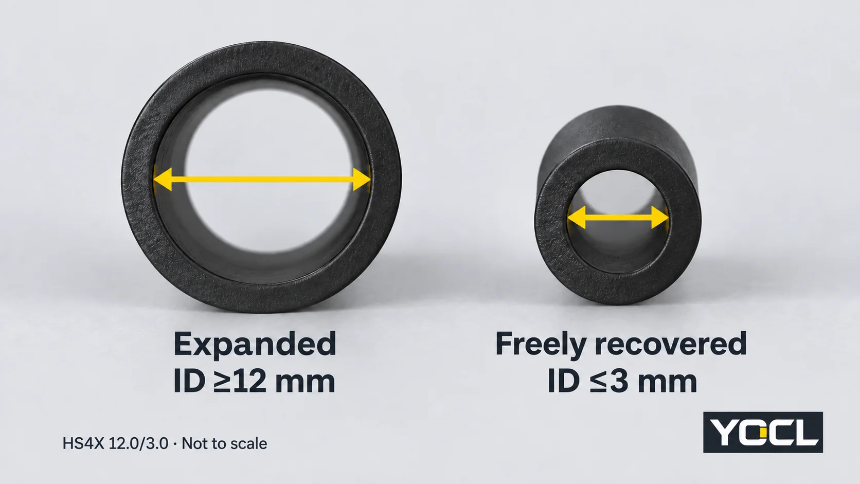
Read the signs as part of the specification: ≥ supplies a lower bound; ≤ supplies an upper bound; ± retains variation around the stated value. Do not erase these signs when copying dimensions into an enquiry.
Also keep the nominal ratio separate. The HS3X 6.4 mm entry lists a recovered limit of ≤2.2 mm, while 6.4 ÷ 3 is approximately 2.13 mm. Replacing 2.2 with that calculation would change the published specification.
For the wider terminology map, see ¿Qué es el tubo termorretráctil? Relaciones, paredes y revestimientos adhesivos.
Use both diameter limits from the same row
For a preliminary check of round parts and open-ended tubing, identify:
- Largest pass-over OD: the widest round feature the unshrunk sleeve must cross, including a connector or joint.
- Smallest covered OD: the narrowest round cable surface onto which the sleeve needs to recover.
Then compare both dimensions with one size row:
Minimum supplied ID > largest pass-over OD
Maximum freely recovered ID < smallest covered OD
de la NASA KSC-E-165 Revision F, §3.8.1.1.1(a) documents this expanded-larger/recovered-smaller relationship for electrical ground-support-equipment fabrication. It supports the dimensional principle, rather than approval of a YOCL assembly.
Equality leaves no dimensional margin. Include component tolerances and the model’s installation allowance; this chart does not prescribe a universal clearance percentage. Flat busbars, irregular connectors and bundles need a geometry review rather than a single round-diameter comparison.
Worked example: a 14 mm feature and a 5 mm cable
Assume the largest round feature is 14 mm OD and the smallest cable jacket is 5 mm OD. These are illustrative inputs, not measurements of a particular installation.
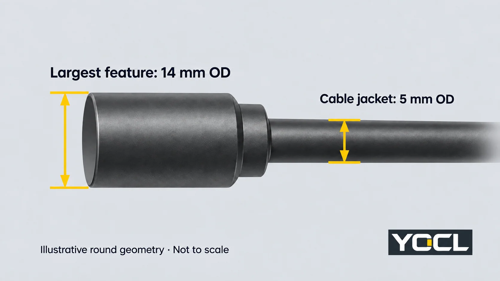
| Series and metric size | Minimum supplied ID | Maximum recovered ID | Supplied minimum >14 mm? | Recovered maximum <5 mm? |
|---|---|---|---|---|
| HS3X 12.7 mm | 12.7 mm | 4.2 mm | No establecido | Superado |
| HS3X 15.0 mm | 15.0 mm | 5.2 mm | Superado | No establecido |
| HS4X 16.0/4.0 mm | 16.0 mm | 4.0 mm | Superado | Superado |
HS4X 16.0/4.0 passes both dimensional inequalities for these inputs. It remains a candidate requiring application review. The HS3X 12.7 row does not establish clearance over 14 mm. Moving up to HS3X 15.0 establishes that clearance, but its 5.2 mm recovered upper limit does not establish contraction below a 5 mm jacket.
“Not established” does not claim every specimen will fail. It means the published bound is insufficient to assure that check. Choose the nearest listed row that satisfies both requirements with the specified allowance, rather than simply taking the next larger size.
What the diameter chart does not decide
Measure the actual insulated cable OD. American Wire Gauge (AWG) or conductor cross-sectional area does not specify the jacket diameter, and a flattened sleeve’s width is not its inside diameter. A nominal fractional-inch label likewise cannot replace the model’s stated diameter fields.
The installed sleeve also needs enough space and coverage. Check wall thickness with its measurement state, finished outside dimensions and the product’s longitudinal-change information. Do not assume a freely recovered wall value is the wall on a partly recovered cable, or apply the diameter shrink ratio to cut length. Where a wall field is labelled “total”, do not add its adhesive thickness again.
For the liner decision, use Tubos termorretráctiles de pared simple vs. pared doble. A successful diameter check alone establishes neither an electrical rating nor a sealed connection.
To confirm a size, use the Catálogo de tubos termorretráctiles YOCL and provide the series, exact size row, largest pass-over dimension, smallest covered dimension and required coverage length. Request the applicable dimensional limits and installation information for the intended material and duty.
Referencias
- Información del producto YOCL — HTS 2:1 Tubo termorretráctil de pared simple. Complete 39-row dimension table, nominal pair meaning and published ± fields; checked 6 October 2026.
- Información del producto YOCL — HS3X 3:1 Tubo termorretráctil de doble pared con adhesivo. Complete 13-row dimension table and supplied/recovered limits; checked 6 October 2026.
- Información del producto YOCL — HS4X 4:1 Tubo termorretráctil de doble pared con adhesivo. Complete nine-row dimension table and supplied/recovered limits; checked 6 October 2026.
- Centro Espacial Kennedy de la NASA — KSC-E-165 Revision F, 20 December 2021, Electrical Ground Support Equipment Fabrication, Specification for. Section 3.8.1.1.1(a), printed page 59; dimensional principle within its ground-support-equipment scope.