
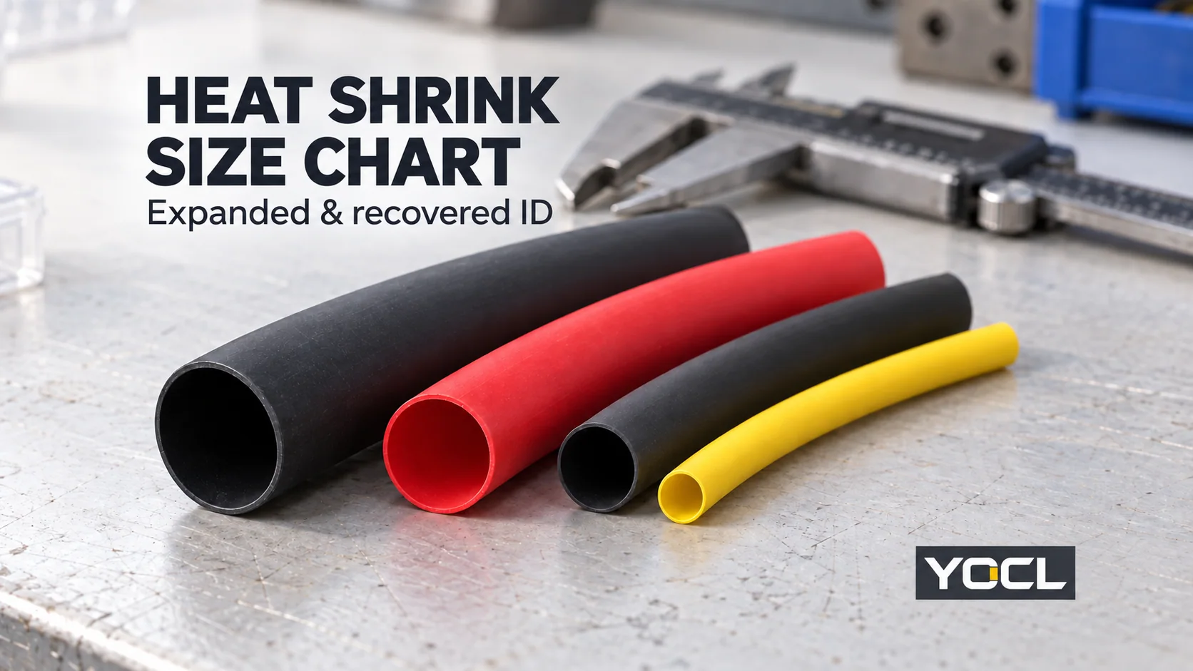
Isıtma öncesi genişletilmiş iç çapı ve büzülmeden sonra serbestçe geri kazanılmış iç çapı olmak üzere iki iç çapa göre bir ısı büzüşmeli makaron boyut tablosunu okuyun. Sağlanan iç çap, en büyük özelliği temizlemelidir; geri kazanılmış iç çap, kavraması gereken yüzeyden daha küçük olmalıdır. Nominal bir boyutu büzülme oranına bölmek yerine, gerçek sıra sınırlarını kullanın.
Aşağıdaki tablolar üç YOCL serisi boyunca 61 boyut girişlerini yeniden üretir. Tüm boyutlar milimetre. dir. Bunlar, her ısı büzüşmeli malzeme için evrensel bir tablo değil, seriye özgü ürün beyanlarıdır.
YOCL ısı ile daralan makaron boyut tabloları
Yaklaşık 2:1 tek cidarlı makaron — HTS
Bu YOCL HTS boyut tablosu eşleştirilmiş nominal boyutları ve büzülmeden önceki/sonraki alanları verir ± toleranslarla. 12.0/6.0 gibi bir boyut okurken bu toleransları dikkate alın; çift, her iki çapın da tam olduğu anlamına gelmez.
| Nominal boyut çifti (mm) | Büzülmeden önceki ID (mm) | Büzülme sonrası alan† (mm) |
|---|---|---|
| 1.0/0.5 | 1.0 ± 0.3 | 0.5 ± 0.1 |
| 1.5/0.75 | 1.5 ± 0.3 | 0.75 ± 0.1 |
| 2.0/1.0 | 2.0 ± 0.3 | 1.0 ± 0.1 |
| 2.5/1.25 | 2.5 ± 0.3 | 1.25 ± 0.1 |
| 3.0/1.5 | 3.0 ± 0.3 | 1.5 ± 0.1 |
| 3.5/1.75 | 3.5 ± 0.3 | 1.75 ± 0.1 |
| 4.0/2.0 | 4.0 ± 0.3 | 2.0 ± 0.1 |
| 5.0/2.5 | 5.0 ± 0.3 | 2.5 ± 0.2 |
| 6.0/3.0 | 6.0 ± 0.4 | 3.0 ± 0.2 |
| 7.0/3.5 | 7.0 ± 0.4 | 3.5 ± 0.2 |
| 8.0/4.0 | 8.0 ± 0.4 | 4.0 ± 0.2 |
| 9.0/4.5 | 9.0 ± 0.4 | 4.5 ± 0.2 |
| 10.0/5.0 | 10.0 ± 0.4 | 5.0 ± 0.2 |
| 11.0/5.5 | 11.0 ± 0.4 | 5.5 ± 0.2 |
| 12.0/6.0 | 12.0 ± 0.4 | 6.0 ± 0.3 |
| 13.0/6.5 | 13.0 ± 0.4 | 6.5 ± 0.3 |
| 14.0/7.0 | 14.0 ± 0.4 | 7.0 ± 0.3 |
| 15.0/7.5 | 15.0 ± 0.4 | 7.5 ± 0.4 |
| 16.0/8.0 | 16.0 ± 0.5 | 8.0 ± 0.3 |
| 17.0/8.5 | 17.0 ± 0.5 | 8.5 ± 0.3 |
| 18.0/9.0 | 18.0 ± 0.5 | 9.0 ± 0.3 |
| 20.0/10.0 | 20.0 ± 0.5 | 10.0 ± 0.3 |
| 22.0/11.0 | 22.0 ± 0.5 | 11.0 ± 0.3 |
| 25.0/12.5 | 25.0 ± 0.8 | 12.5 ± 1.0 |
| 28.0/14.0 | 28.0 ± 0.8 | 14.0 ± 1.0 |
| 30.0/15.0 | 30.0 ± 0.8 | 15.0 ± 1.0 |
| 35.0/17.5 | 35.0 ± 0.8 | 17.5 ± 1.0 |
| 40.0/20.0 | 40.0 ± 1.5 | 20.0 ± 1.0 |
| 45.0/22.5 | 45.0 ± 1.5 | 22.5 ± 1.0 |
| 50.0/25.0 | 50.0 ± 1.5 | 25.0 ± 1.0 |
| 60.0/30.0 | 60.0 ± 1.5 | 30.0 ± 1.5 |
| 70.0/35.0 | 70.0 ± 1.5 | 35.0 ± 1.5 |
| 80.0/40.0 | 80.0 ± 1.5 | 40.0 ± 1.5 |
| 90.0/45.0 | 90.0 ± 1.5 | 45.0 ± 1.5 |
| 100.0/50.0 | 100.0 ± 1.5 | 50.0 ± 1.5 |
| 120.0/60.0 | 120.0 ± 1.5 | 60.0 ± 1.5 |
| 150.0/75.0 | 150.0 ± 1.5 | 75.0 ± 1.5 |
| 180.0/90.0 | 180.0 ± 1.5 | 90.0 ± 1.5 |
| 200.0/100.0 | 200.0 ± 1.5 | 100.0 ± 1.5 |
† Kaynak, ± değerleri listelerken büzülme sonrası sütununu “Maks. I.D. büzülmeden sonra” olarak başlıklandırır. Bu değerler, niteliksiz maksimum limitler olarak yeniden dökülmek yerine burada değişmeden tekrarlanır. Herhangi bir sınırın yakınına bir uyum onaylamadan önce seçilen HTS boyutu için kesin tedarik edilen/geri kazanılan limitleri alın.
3:1 yapışkan astarlı boru — HS3X
Bu YOCL HS3X boyut tablosu belirtir sağlanan minimum ID ve geri kazanılan maksimum ID. Aşağıdaki Metrik girişleri YOCL'nin yayınlanan değerlerini korur; kesirli inç boyut etiketlerinden yeniden hesaplanmazlar.
| Metrik boyut girişi (mm) | Sağlanan ID (mm), minimum | Geri kazanılan ID (mm), maksimum |
|---|---|---|
| 2.4 | ≥2.4 | ≤0.8 |
| 3.2 | ≥3.2 | ≤1.0 |
| 4.8 | ≥4.8 | ≤1.6 |
| 6.4 | ≥6.4 | ≤2.2 |
| 7.9 | ≥7.9 | ≤2.7 |
| 9.5 | ≥9.5 | ≤3.2 |
| 12.7 | ≥12.7 | ≤4.2 |
| 15.0 | ≥15.0 | ≤5.2 |
| 19.1 | ≥19.1 | ≤6.3 |
| 25.4 | ≥25.4 | ≤8.5 |
| 30.0 | ≥30.0 | ≤10.2 |
| 39.0 | ≥39.0 | ≤13.5 |
| 50.0 | ≥50.0 | ≤17.0 |
4:1 yapışkan astarlı boru — HS4X
Bu YOCL HS4X boyut tablosu sağlanan/geri kazanılan boyut çiftlerini ve açık ≥/≤ sınırlarını kullanır. Örneğin, 16.0/4.0 en az 16.0 mm olan sağlanan bir çap ve en fazla 4.0 mm olan geri kazanılmış bir çap belirtir.
| Metrik boyut girişi (mm) | Sağlanan ID (mm), minimum | Geri kazanılan ID (mm), maksimum |
|---|---|---|
| 4.0/1.0 | ≥4.0 | ≤1.0 |
| 6.0/1.5 | ≥6.0 | ≤1.5 |
| 8.0/2.0 | ≥8.0 | ≤2.0 |
| 12.0/3.0 | ≥12.0 | ≤3.0 |
| 16.0/4.0 | ≥16.0 | ≤4.0 |
| 20.0/5.0 | ≥20.0 | ≤5.0 |
| 24.0/6.0 | ≥24.0 | ≤6.0 |
| 32.0/8.0 | ≥32.0 | ≤8.0 |
| 52.0/13.0 | ≥52.0 | ≤13.0 |
Bu tablolar yalnızca HTS, HS3X ve HS4X'yi kapsar. Diğer tek cidarlı, yarı sert, bara veya özel kaliteler kendi boyut tablolarına ihtiyaç duyar; eşleşen bir oran boyutlarını değiştirilebilir yapmaz.
Genişletilmiş, geri kazanılmış ve takılmış çaplar farklı durumlardır
İç çap (ID) boru çapını ölçer. Dış çap (OD) kabloyu veya sarması gereken bileşeni ölçer.
- Genişletilmiş/teslim edildiği gibi: geçiş kontrolü için kullanılan, ısıtmadan önceki mevcut iç çap.
- Serbestçe geri kazanılmış: içinde kısıtlayıcı bir nesne olmadan belirtilen geri kazanım koşulları altında ulaşılan iç çap.
- Takılmış: kılıf nesnenin etrafına uyum sağlar. Serbest geri kazanım iç çapından daha büyük bir kablo, bu iç çapa ulaşmasını engeller.
HS4X 12.0/3.0 satırı için, iki katalog alanı ≥12.0 mm teslim edilmiş ve ≤3.0 mm geri kazanılmış değerindedir. Hiçbir alan, daha büyük bir kablo etrafına monte edilmiş bir kılıfın 3.0 mm iç çapa sahip olacağını garanti etmez.
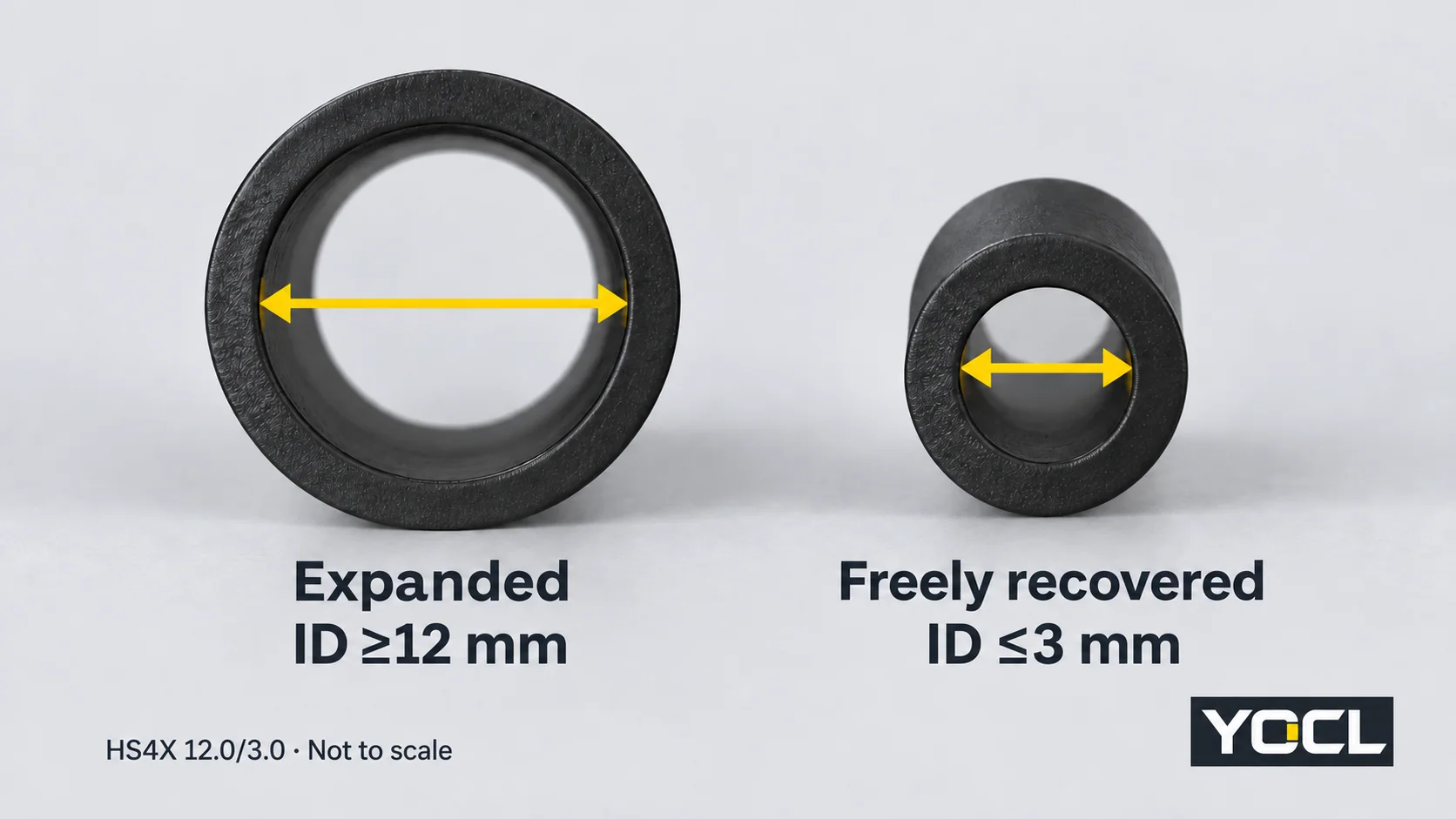
Read the signs as part of the specification: ≥ supplies a lower bound; ≤ supplies an upper bound; ± retains variation around the stated value. Do not erase these signs when copying dimensions into an enquiry.
Also keep the nominal ratio separate. The HS3X 6.4 mm entry lists a recovered limit of ≤2.2 mm, while 6.4 ÷ 3 is approximately 2.13 mm. Replacing 2.2 with that calculation would change the published specification.
For the wider terminology map, see Isı Daralan Makaron Nedir? Oranlar, Duvarlar ve Yapışkan Astarlar.
Use both diameter limits from the same row
For a preliminary check of round parts and open-ended tubing, identify:
- Largest pass-over OD: the widest round feature the unshrunk sleeve must cross, including a connector or joint.
- Smallest covered OD: the narrowest round cable surface onto which the sleeve needs to recover.
Then compare both dimensions with one size row:
Minimum supplied ID > largest pass-over OD
Maximum freely recovered ID < smallest covered OD
NASA’nın KSC-E-165 Revizyon F, §3.8.1.1.1(a) documents this expanded-larger/recovered-smaller relationship for electrical ground-support-equipment fabrication. It supports the dimensional principle, rather than approval of a YOCL assembly.
Equality leaves no dimensional margin. Include component tolerances and the model’s installation allowance; this chart does not prescribe a universal clearance percentage. Flat busbars, irregular connectors and bundles need a geometry review rather than a single round-diameter comparison.
Worked example: a 14 mm feature and a 5 mm cable
Assume the largest round feature is 14 mm OD and the smallest cable jacket is 5 mm OD. These are illustrative inputs, not measurements of a particular installation.
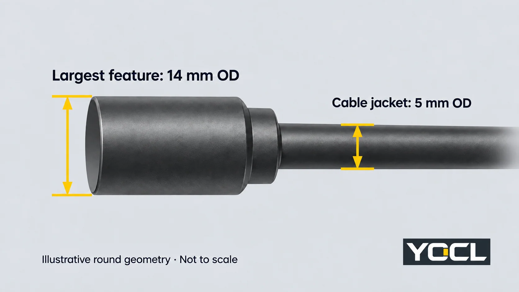
| Series and metric size | Minimum supplied ID | Maximum recovered ID | Supplied minimum >14 mm? | Recovered maximum <5 mm? |
|---|---|---|---|---|
| HS3X 12.7 mm | 12.7 mm | 4.2 mm | Belirlenmemiş | Geçti |
| HS3X 15.0 mm | 15.0 mm | 5.2 mm | Geçti | Belirlenmemiş |
| HS4X 16.0/4.0 mm | 16.0 mm | 4.0 mm | Geçti | Geçti |
HS4X 16.0/4.0 passes both dimensional inequalities for these inputs. It remains a candidate requiring application review. The HS3X 12.7 row does not establish clearance over 14 mm. Moving up to HS3X 15.0 establishes that clearance, but its 5.2 mm recovered upper limit does not establish contraction below a 5 mm jacket.
“Not established” does not claim every specimen will fail. It means the published bound is insufficient to assure that check. Choose the nearest listed row that satisfies both requirements with the specified allowance, rather than simply taking the next larger size.
What the diameter chart does not decide
Measure the actual insulated cable OD. American Wire Gauge (AWG) or conductor cross-sectional area does not specify the jacket diameter, and a flattened sleeve’s width is not its inside diameter. A nominal fractional-inch label likewise cannot replace the model’s stated diameter fields.
The installed sleeve also needs enough space and coverage. Check wall thickness with its measurement state, finished outside dimensions and the product’s longitudinal-change information. Do not assume a freely recovered wall value is the wall on a partly recovered cable, or apply the diameter shrink ratio to cut length. Where a wall field is labelled “total”, do not add its adhesive thickness again.
For the liner decision, use Tek Duvarlı ve Çift Duvarlı Isıyla Daralan Makaron Karşılaştırması. A successful diameter check alone establishes neither an electrical rating nor a sealed connection.
To confirm a size, use the YOCL ısıyla daralan makaron kataloğu and provide the series, exact size row, largest pass-over dimension, smallest covered dimension and required coverage length. Request the applicable dimensional limits and installation information for the intended material and duty.
Referanslar
- YOCL ürün bilgileri — HTS 2:1 Tek Duvarlı Isıyla Daralan Makaron. Complete 39-row dimension table, nominal pair meaning and published ± fields; checked 6 October 2026.
- YOCL ürün bilgileri — HS3X 3:1 Yapışkan Astarlı Çift Cidarlı Isıyla Daralan Makaron. Complete 13-row dimension table and supplied/recovered limits; checked 6 October 2026.
- YOCL ürün bilgileri — HS4X 4:1 Çift Cidarlı Yapışkan Astarlı Isıyla Daralan Makaron. Complete nine-row dimension table and supplied/recovered limits; checked 6 October 2026.
- NASA Kennedy Uzay Merkezi — KSC-E-165 Revision F, 20 December 2021, Electrical Ground Support Equipment Fabrication, Specification for. Section 3.8.1.1.1(a), printed page 59; dimensional principle within its ground-support-equipment scope.