
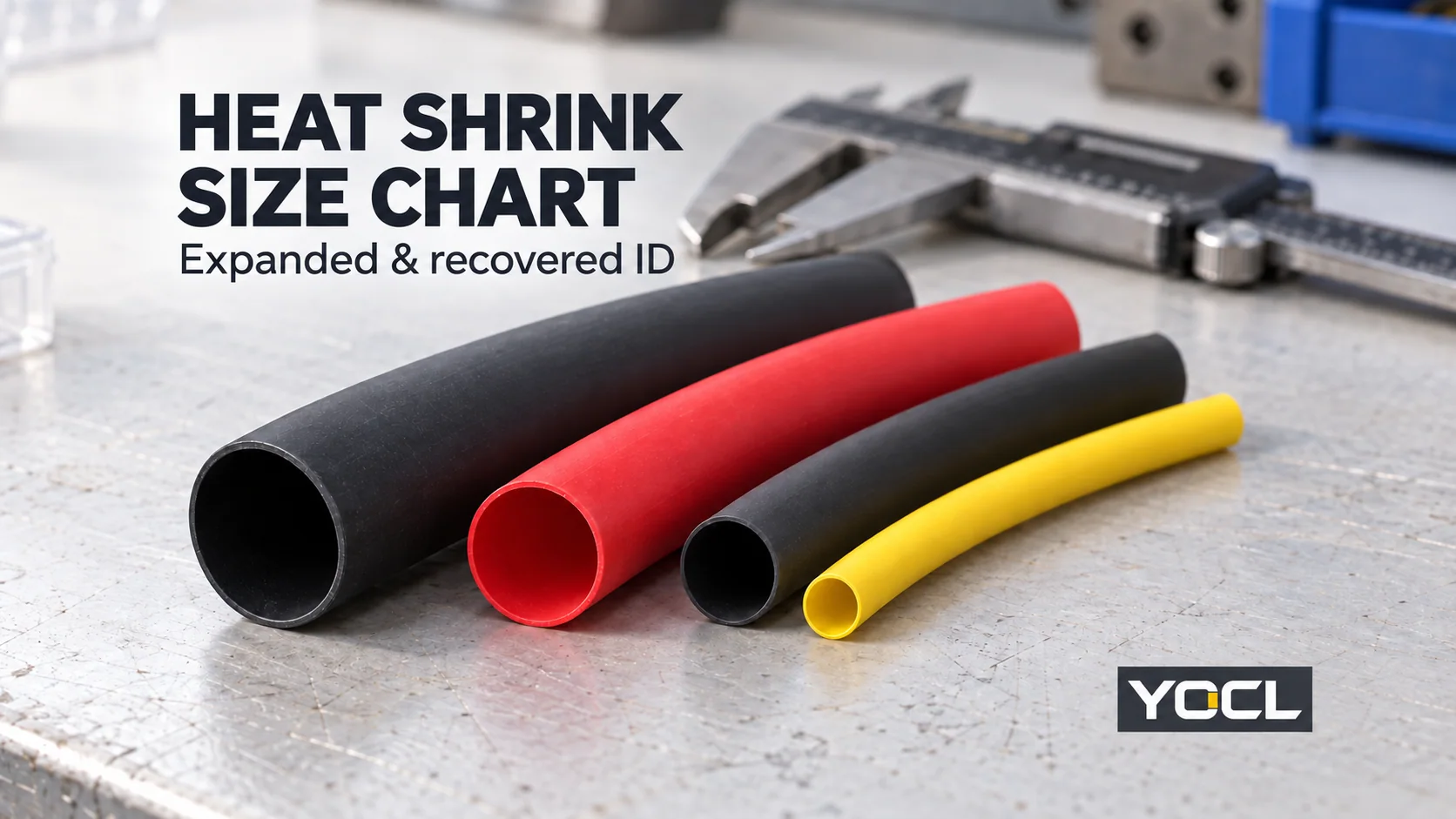
Lesen Sie eine Schrumpfschlauch-Größentabelle anhand von zwei Innendurchmessern: der aufgeweiteten Bohrung vor dem Erhitzen und der frei geschrumpften Bohrung nach dem Schrumpfen. Die gelieferte Bohrung muss das größte Merkmal freigeben; die geschrumpfte Bohrung muss kleiner sein als die Oberfläche, die sie greifen muss. Verwenden Sie die tatsächlichen Reihengrenzen, anstatt eine Nenngröße durch das Schrumpfverhältnis zu teilen.
Die folgenden Tabellen geben wieder 61 Größeneinträge über drei YOCL Serien hinweg. Alle Maße sind in Millimetern. Es handelt sich um serienspezifische Produktdaten, nicht um eine universelle Tabelle für jedes Schrumpfschlauchmaterial.
YOCL Schrumpfschlauch Größentabellen
Ungefähr 2:1 einwandiger Schlauch — HTS
Das YOCL HTS-Maßtabelle gibt gepaarte Nenngrößen und Felder vor/nach dem Schrumpfen mit ± Toleranzen. Behalten Sie diese Toleranzen bei, wenn Sie eine Größe wie 12.0/6.0 lesen; das Paar bedeutet nicht, dass beide Durchmesser exakt sind.
| Nennmaßpaar (mm) | ID vor dem Schrumpfen (mm) | Nachschrumpffeld † (mm) |
|---|---|---|
| 1.0/0.5 | 1.0 ± 0.3 | 0.5 ± 0.1 |
| 1.5/0.75 | 1.5 ± 0.3 | 0.75 ± 0.1 |
| 2.0/1.0 | 2.0 ± 0.3 | 1.0 ± 0.1 |
| 2.5/1.25 | 2.5 ± 0.3 | 1.25 ± 0.1 |
| 3.0/1.5 | 3.0 ± 0.3 | 1.5 ± 0.1 |
| 3.5/1.75 | 3.5 ± 0.3 | 1.75 ± 0.1 |
| 4.0/2.0 | 4.0 ± 0.3 | 2.0 ± 0.1 |
| 5.0/2.5 | 5.0 ± 0.3 | 2.5 ± 0.2 |
| 6.0/3.0 | 6.0 ± 0.4 | 3.0 ± 0.2 |
| 7.0/3.5 | 7.0 ± 0.4 | 3.5 ± 0.2 |
| 8.0/4.0 | 8.0 ± 0.4 | 4.0 ± 0.2 |
| 9.0/4.5 | 9.0 ± 0.4 | 4.5 ± 0.2 |
| 10.0/5.0 | 10.0 ± 0.4 | 5.0 ± 0.2 |
| 11.0/5.5 | 11.0 ± 0.4 | 5.5 ± 0.2 |
| 12.0/6.0 | 12.0 ± 0.4 | 6.0 ± 0.3 |
| 13.0/6.5 | 13.0 ± 0.4 | 6.5 ± 0.3 |
| 14.0/7.0 | 14.0 ± 0.4 | 7.0 ± 0.3 |
| 15.0/7.5 | 15.0 ± 0.4 | 7.5 ± 0.4 |
| 16.0/8.0 | 16.0 ± 0.5 | 8.0 ± 0.3 |
| 17.0/8.5 | 17.0 ± 0.5 | 8.5 ± 0.3 |
| 18.0/9.0 | 18.0 ± 0.5 | 9.0 ± 0.3 |
| 20.0/10.0 | 20.0 ± 0.5 | 10.0 ± 0.3 |
| 22.0/11.0 | 22.0 ± 0.5 | 11.0 ± 0.3 |
| 25.0/12.5 | 25.0 ± 0.8 | 12.5 ± 1.0 |
| 28.0/14.0 | 28.0 ± 0.8 | 14.0 ± 1.0 |
| 30.0/15.0 | 30.0 ± 0.8 | 15.0 ± 1.0 |
| 35.0/17.5 | 35.0 ± 0.8 | 17.5 ± 1.0 |
| 40.0/20.0 | 40.0 ± 1.5 | 20.0 ± 1.0 |
| 45.0/22.5 | 45.0 ± 1.5 | 22.5 ± 1.0 |
| 50.0/25.0 | 50.0 ± 1.5 | 25.0 ± 1.0 |
| 60.0/30.0 | 60.0 ± 1.5 | 30.0 ± 1.5 |
| 70.0/35.0 | 70.0 ± 1.5 | 35.0 ± 1.5 |
| 80.0/40.0 | 80.0 ± 1.5 | 40.0 ± 1.5 |
| 90.0/45.0 | 90.0 ± 1.5 | 45.0 ± 1.5 |
| 100.0/50.0 | 100.0 ± 1.5 | 50.0 ± 1.5 |
| 120.0/60.0 | 120.0 ± 1.5 | 60.0 ± 1.5 |
| 150.0/75.0 | 150.0 ± 1.5 | 75.0 ± 1.5 |
| 180.0/90.0 | 180.0 ± 1.5 | 90.0 ± 1.5 |
| 200.0/100.0 | 200.0 ± 1.5 | 100.0 ± 1.5 |
† Die Quelle bezeichnet ihre Spalte nach dem Schrumpfen als “Max. I.D nach dem Schrumpfen” und listet ± Werte auf. Diese Werte werden hier unverändert wiedergegeben, anstatt sie als uneingeschränkte Grenzwerte neu zu formulieren. Holen Sie die endgültigen gelieferten/wiederhergestellten Grenzwerte für die gewählte HTS-Größe ein, bevor Sie eine Passung nahe einer der Grenzen genehmigen.
3:1 klebstoffausgekleideter Schlauch — HS3X
Das YOCL HS3X Maßtabelle gibt einen minimalen gelieferten ID und maximalen wiederhergestellten ID. Die unten aufgeführten metrischen Einträge behalten die veröffentlichten Werte von YOCL bei; sie werden nicht aus bruchzahligen Zollgrößenbezeichnungen neu berechnet.
| Metrische Größeneingabe (mm) | Gelieferte ID (mm), Minimum | Wiederhergestellte ID (mm), Maximum |
|---|---|---|
| 2.4 | ≥2.4 | ≤0.8 |
| 3.2 | ≥3.2 | ≤1.0 |
| 4.8 | ≥4.8 | ≤1.6 |
| 6.4 | ≥6.4 | ≤2.2 |
| 7.9 | ≥7.9 | ≤2.7 |
| 9.5 | ≥9.5 | ≤3.2 |
| 12.7 | ≥12.7 | ≤4.2 |
| 15.0 | ≥15.0 | ≤5.2 |
| 19.1 | ≥19.1 | ≤6.3 |
| 25.4 | ≥25.4 | ≤8.5 |
| 30.0 | ≥30.0 | ≤10.2 |
| 39.0 | ≥39.0 | ≤13.5 |
| 50.0 | ≥50.0 | ≤17.0 |
4:1 klebstoffausgekleidete Schlauch — HS4X
Das YOCL HS4X Maßtabelle verwendet gelieferte/wiederhergestellte Größenpaare und explizite ≥/≤ Grenzwerte. Zum Beispiel identifiziert 16.0/4.0 eine gelieferte Bohrung von mindestens 16.0 mm und eine wiederhergestellte Bohrung von höchstens 4.0 mm.
| Metrische Größeneingabe (mm) | Gelieferte ID (mm), Minimum | Wiederhergestellte ID (mm), Maximum |
|---|---|---|
| 4.0/1.0 | ≥4.0 | ≤1.0 |
| 6.0/1.5 | ≥6.0 | ≤1.5 |
| 8.0/2.0 | ≥8.0 | ≤2.0 |
| 12.0/3.0 | ≥12.0 | ≤3.0 |
| 16.0/4.0 | ≥16.0 | ≤4.0 |
| 20.0/5.0 | ≥20.0 | ≤5.0 |
| 24.0/6.0 | ≥24.0 | ≤6.0 |
| 32.0/8.0 | ≥32.0 | ≤8.0 |
| 52.0/13.0 | ≥52.0 | ≤13.0 |
Diese Tabellen decken nur HTS, HS3X und HS4X ab. Andere einwandige, halbstarre, Sammelschienen- oder spezielle Qualitäten benötigen eigene Maßtabelle; ein passendes Verhältnis macht ihre Größen nicht austauschbar.
Erweiterte, zurückgebildete und installierte Durchmesser sind unterschiedliche Zustände
Innendurchmesser (ID) misst die Bohrung des Schlauchs. Außendurchmesser (OD) misst das Kabel oder die Komponente, die es umgeben muss.
- Erweitert/wie geliefert: the bore available before heating, used for the pass-over check.
- Frei zurückgebildet: the bore reached under specified recovery conditions without an internal object restricting contraction.
- Installiert: the sleeve conforms around the object. A cable that is larger than the free-recovery bore prevents it reaching that bore.
For the HS4X 12.0/3.0 row, the two catalogue fields are ≥12.0 mm supplied and ≤3.0 mm recovered. Neither field promises that an installed sleeve around a larger cable will have a 3.0 mm bore.
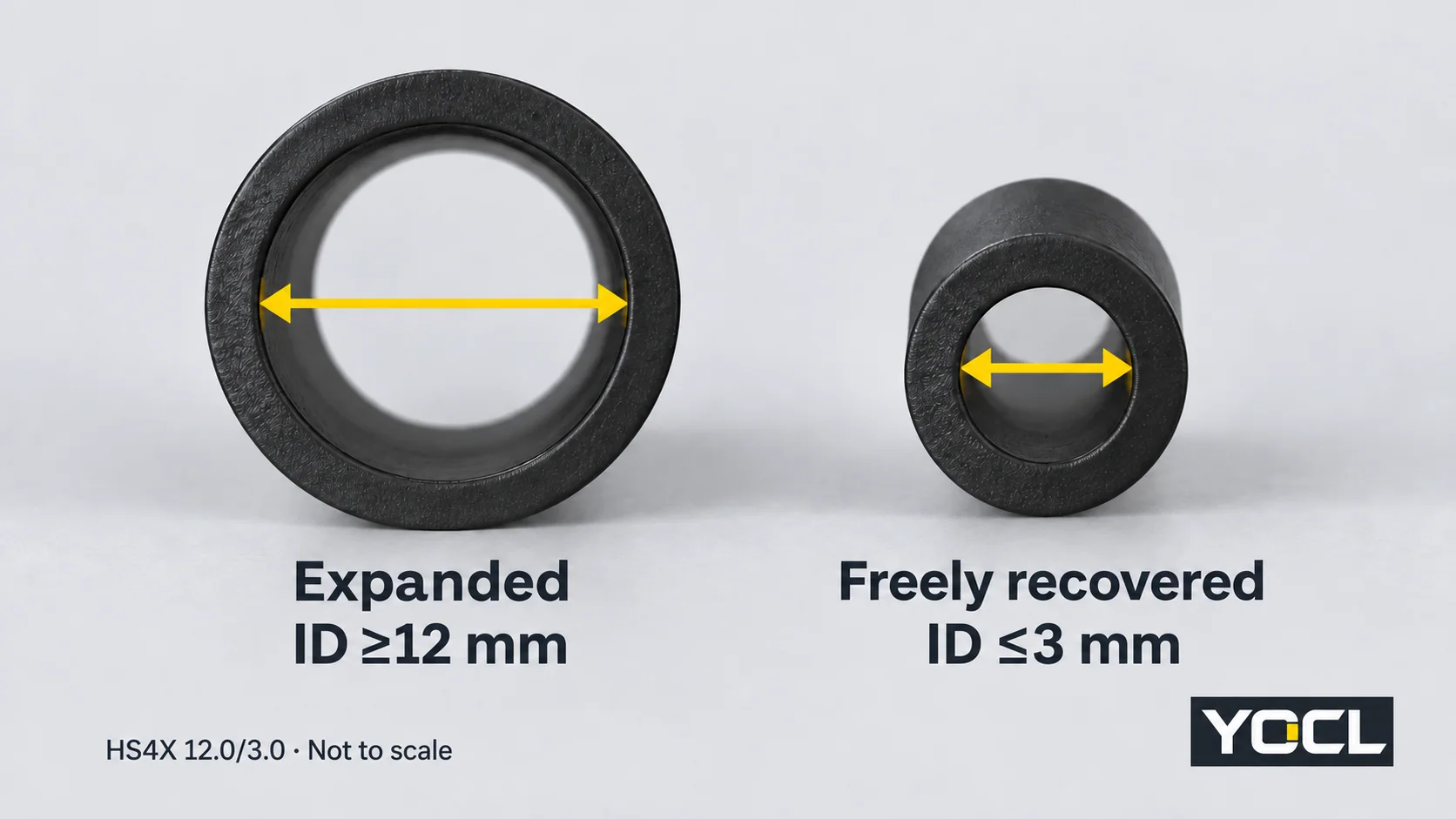
Read the signs as part of the specification: ≥ supplies a lower bound; ≤ supplies an upper bound; ± retains variation around the stated value. Do not erase these signs when copying dimensions into an enquiry.
Also keep the nominal ratio separate. The HS3X 6.4 mm entry lists a recovered limit of ≤2.2 mm, while 6.4 ÷ 3 is approximately 2.13 mm. Replacing 2.2 with that calculation would change the published specification.
For the wider terminology map, see Was ist Schrumpfschlauch? Verhältnisse, Wandstärken und Klebstoffauskleidungen.
Use both diameter limits from the same row
For a preliminary check of round parts and open-ended tubing, identify:
- Largest pass-over OD: the widest round feature the unshrunk sleeve must cross, including a connector or joint.
- Smallest covered OD: the narrowest round cable surface onto which the sleeve needs to recover.
Then compare both dimensions with one size row:
Minimum supplied ID > largest pass-over OD
Maximum freely recovered ID < smallest covered OD
NASA's KSC-E-165 Revision F, §3.8.1.1.1(a) documents this expanded-larger/recovered-smaller relationship for electrical ground-support-equipment fabrication. It supports the dimensional principle, rather than approval of a YOCL assembly.
Equality leaves no dimensional margin. Include component tolerances and the model’s installation allowance; this chart does not prescribe a universal clearance percentage. Flat busbars, irregular connectors and bundles need a geometry review rather than a single round-diameter comparison.
Worked example: a 14 mm feature and a 5 mm cable
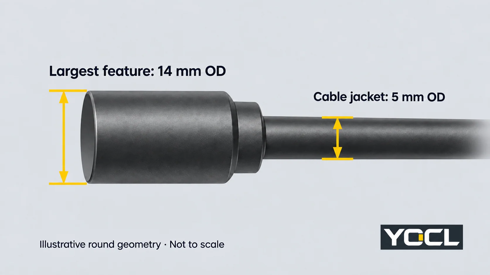
Assume the largest round feature is 14 mm OD and the smallest cable jacket is 5 mm OD. These are illustrative inputs, not measurements of a particular installation.
| Series and metric size | Minimum supplied ID | Maximum recovered ID | Supplied minimum >14 mm? | Recovered maximum <5 mm? |
|---|---|---|---|---|
| HS3X 12.7 mm | 12.7 mm | 4.2 mm | Nicht ermittelt | Bestanden |
| HS3X 15.0 mm | 15.0 mm | 5.2 mm | Bestanden | Nicht ermittelt |
| HS4X 16.0/4.0 mm | 16.0 mm | 4.0 mm | Bestanden | Bestanden |
HS4X 16.0/4.0 passes both dimensional inequalities for these inputs. It remains a candidate requiring application review. The HS3X 12.7 row does not establish clearance over 14 mm. Moving up to HS3X 15.0 establishes that clearance, but its 5.2 mm recovered upper limit does not establish contraction below a 5 mm jacket.
“Not established” does not claim every specimen will fail. It means the published bound is insufficient to assure that check. Choose the nearest listed row that satisfies both requirements with the specified allowance, rather than simply taking the next larger size.
What the diameter chart does not decide
Measure the actual insulated cable OD. American Wire Gauge (AWG) or conductor cross-sectional area does not specify the jacket diameter, and a flattened sleeve’s width is not its inside diameter. A nominal fractional-inch label likewise cannot replace the model’s stated diameter fields.
The installed sleeve also needs enough space and coverage. Check wall thickness with its measurement state, finished outside dimensions and the product’s longitudinal-change information. Do not assume a freely recovered wall value is the wall on a partly recovered cable, or apply the diameter shrink ratio to cut length. Where a wall field is labelled “total”, do not add its adhesive thickness again.
For the liner decision, use Einschichtige vs. zweischichtige Schrumpfschläuche. A successful diameter check alone establishes neither an electrical rating nor a sealed connection.
To confirm a size, use the YOCL Schrumpfschlauchkatalog and provide the series, exact size row, largest pass-over dimension, smallest covered dimension and required coverage length. Request the applicable dimensional limits and installation information for the intended material and duty.
Referenzen
- YOCL Produktinformationen — HTS 2:1 Einwandige Schrumpfschlauch-Tubes. Complete 39-row dimension table, nominal pair meaning and published ± fields; checked 6 October 2026.
- YOCL Produktinformationen — HS3X 3:1 Doppeltwandige Schrumpfschläuche mit Kleber. Complete 13-row dimension table and supplied/recovered limits; checked 6 October 2026.
- YOCL Produktinformationen — HS4X 4:1 Doppeltwandige Schrumpfschläuche mit Kleber. Complete nine-row dimension table and supplied/recovered limits; checked 6 October 2026.
- NASA Kennedy Space Center — KSC-E-165 Revision F, 20 December 2021, Electrical Ground Support Equipment Fabrication, Specification for. Section 3.8.1.1.1(a), printed page 59; dimensional principle within its ground-support-equipment scope.