
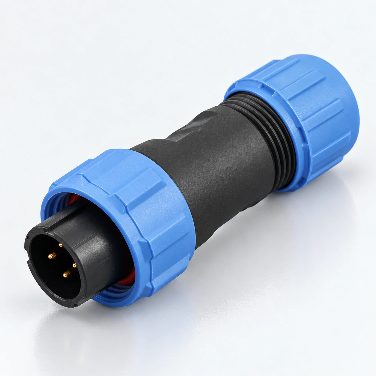
Connecteurs circulaires étanches SP13 IP68
YOCL Les connecteurs circulaires étanches ELECTRIC SP13 combinent un verrouillage fileté avec une terminaison à souder pour les connexions de câbles et de panneaux.
- Contacts : 2 / 3 / 4 / 5 / 6 / 7 / 9.
- Protection : IP68.
- Diamètre du câble : 4–6.5 mm ou 5–8 mm.
- Formats : Fiche câble, embase câble en ligne, embase panneau écrou arrière et embase à bride.
- Caractéristiques : sélectionnez le courant et la AC tension de fonctionnement par nombre de contacts dans le tableau des spécifications.
Aperçu
Les connecteurs circulaires étanches YOCL ELECTRIC SP13 offrent un verrouillage fileté et une terminaison à souder pour les connexions de câbles et de panneaux détachables. La famille utilise des contacts en cuivre plaqué or, des boîtiers thermoplastiques et des isolants en PPS, avec un indice de protection IP68.
La série couvre sept configurations de contacts : 2, 3, 4, 5, 6, 7 et 9 contacts. Les configurations à 2 et 3 contacts sont évaluées à 13 A et 250 V AC ; les configurations avec plus de contacts ont leurs propres caractéristiques indiquées ci-dessous. Deux tailles de passe-fils de câble accueillent des diamètres de câble de 4–6.5 mm ou 5–8 mm.
Caractéristiques
- Verrouillage fileté : un accouplement à vis maintient les moitiés de connecteur d'accouplement.
- Options de contact : contacts 2 / 3 / 4 / 5 / 6 / 7 / 9, avec des caractéristiques électriques sélectionnées par la configuration des contacts.
- Contacts en cuivre plaqué or : terminaison à souder pour les configurations listées sur cette page.
- Formats de câble et de panneau : Fiche câble, embase câble en ligne, embase panneau écrou arrière et embase à bride.
- Sélection du joint de câble : diamètre de câble 4–6.5 mm ou 5–8 mm.
- Plage de température : −40°C à +85°C, avec 500 cycles d'accouplement listés pour la série.
Spécifications techniques
Spécifications courantes
| Paramètre | Spécification |
|---|---|
| Marque | YOCL ÉLECTRIQUE |
| Série | SP13 |
| Configurations de contacts | 2 / 3 / 4 / 5 / 6 / 7 / 9 contacts |
| Accouplement | Verrouillage fileté |
| Terminaison | Soudure |
| Matériau du boîtier | Thermoplastique PC / PA66 |
| Indice de inflammabilité du matériau du boîtier | V-0 |
| Matériau de l'isolant | PPS thermoplastique |
| Matériau du contact | Cuivre plaqué or |
| Indice de protection | IP68 |
| Plage de température | −40°C à +85°C |
| Cycles d'accouplement | 500 |
| Résistance d'isolement | 2000 MΩ |
| Joint de câble type I | 4–6.5 mm ; le type I n'est pas indiqué dans la désignation du modèle |
| Joint de câble type II | 5–8 mm |
Caractéristiques électriques par disposition des contacts
| Contacts | Courant nominal | Tension de service | Diamètre × quantité de contacts | Section transversale maximale du conducteur | Référence catalogue AWG |
|---|---|---|---|---|---|
| 2 | 13 A | 250 V AC | Ø1.6 mm × 2 | ≤2.0 mm² | 14 |
| 3 | 13 A | 250 V AC | Ø1.6 mm × 3 | ≤2.0 mm² | 14 |
| 4 | 5 A | 200 V AC | Ø1.0 mm × 4 | ≤0.75 mm² | 18 |
| 5 | 5 A | 180 V AC | Ø1.0 mm × 5 | ≤0.75 mm² | 18 |
| 6 | 5 A | 125 V AC | Ø1.0 mm × 6 | ≤0.75 mm² | 18 |
| 7 | 5 A | 125 V AC | Ø1.0 mm × 7 | ≤0.75 mm² | 18 |
| 9 | 3 A | 125 V AC | Ø0.7 mm × 9 | ≤0.5 mm² | 20 |
Choose the current, working voltage and conductor limit from the same row. The AWG values are the paired references supplied with the metric wire sizes; the conductor limit is expressed in mm².
Dielectric Withstand and Contact Resistance
| Contacts | Tension de tenue diélectrique | Résistance de contact |
|---|---|---|
| 2 | 1500 V AC for 1 minute | 2.5 mΩ |
| 3 | 1500 V AC for 1 minute | 2.5 mΩ |
| 4 | 1500 V AC for 1 minute | 5 mΩ |
| 5 | 1000 V AC for 1 minute | 5 mΩ |
| 6 | 1000 V AC for 1 minute | 5 mΩ |
| 7 | 1000 V AC for 1 minute | 5 mΩ |
| 9 | 1000 V AC for 1 minute | 10 mΩ |
The dielectric withstand value is a one-minute test voltage, separate from the working voltage.
Dimension
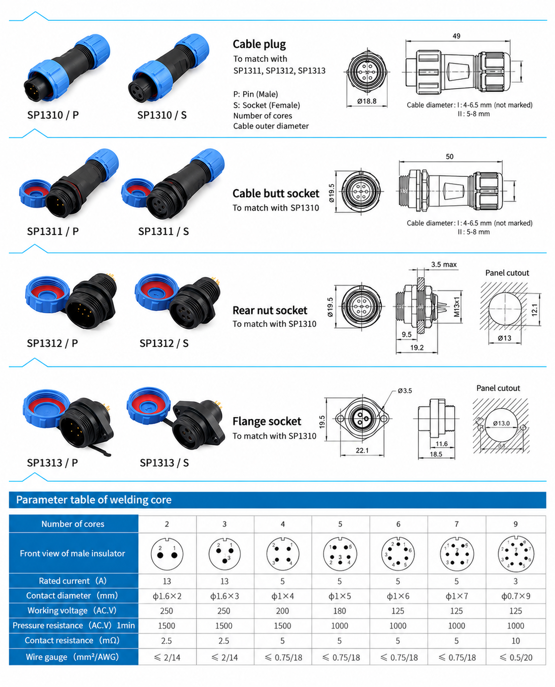
Dimensions du corps du connecteur
| Format | Famille de modèles | Drawing dimensions |
|---|---|---|
| Fiche de câble | SP1310 | 49.0 mm length; Ø18.8 mm front diameter |
| Inline cable socket | SP1311 | 50.0 mm length; Ø19.5 mm front diameter |
| Rear-nut panel socket | SP1312 | 19.2 mm length; Ø19.5 mm front diameter; M13 × 1 mounting thread |
| Flange socket | SP1313 | 18.5 mm length; 19.5 mm front height; Ø3.5 mm mounting holes; 22.1 mm body mounting-hole pitch |
Panel Mounting Dimensions
| Format | Panel opening | Détails de montage |
|---|---|---|
| Rear-nut panel socket | Ø13.0 mm opening with 12.1 mm across flats | Maximum panel thickness: 3.5 mm |
| Flange socket | Ø13.0 mm centre opening | Two Ø3.5 mm holes at 22.0 mm pitch |
Body dimensions and panel openings are listed separately. The flange body drawing gives 22.1 mm mounting-hole pitch, while the panel opening drawing gives 22.0 mm; use the panel opening dimensions when planning the panel.
Formats de connecteurs et désignations de modèles
| Format | Pin-contact designation | Socket-contact designation | Matching format |
|---|---|---|---|
| Fiche de câble | SP1310/P | SP1310/S | Mates with SP1311, SP1312 or SP1313 of the corresponding contact arrangement |
| Inline cable socket | SP1311/P | SP1311/S | Cable-to-cable connection with SP1310 |
| Rear-nut panel socket | SP1312/P | SP1312/S | Panel connection with SP1310 |
| Flange socket | SP1313/P | SP1313/S | Flange-mounted panel connection with SP1310 |
P identifies pin contacts and S identifies socket contacts. Both contact types are offered in each listed body format; choose complementary contacts and the same contact count for the mating pair. The designations above identify the connector format; specify the contact count separately in the enquiry.
Guide de sélection
- Select SP13 and the required contact count.
- Check the rated current, AC working voltage and conductor cross-section together in the electrical table.
- Choose a cable-to-cable or cable-to-panel connection and select the corresponding body format.
- Select Type I for 4–6.5 mm cable or Type II for 5–8 mm cable. Type I is unmarked in the catalogue designation; specify the seal size explicitly when ordering.
- Specify complementary P and S contacts and check the applicable body and panel dimensions.
Informations de commande
For a quotation, provide the SP13 model family, contact count, P or S contact type, cable outer diameter, mating connector format and required quantity. For panel sockets, include the panel thickness and mounting format.