
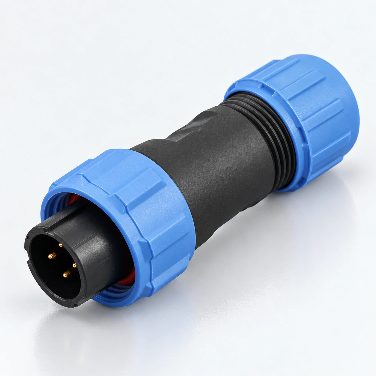
SP13 IP68 Su Geçirmez Yuvarlak Konnektörler
YOCL ELEKTRİKLİ SP13 su geçirmez dairesel konektörler, kablo ve panel bağlantıları için lehim sonlandırmalı dişli kilitlemeyi birleştirir.
- Kontaklar: 2 / 3 / 4 / 5 / 6 / 7 / 9.
- Koruma: IP68.
- Kablo çapı: 4–6.5 mm veya 5–8 mm.
- Formatlar: kablo fişi, hat içi kablo soketi, arka somunlu panel soketi ve flanş soketi.
- Değerlendirmeler: seçim akımı ve AC çalışma gerilimi, teknik özellik tablosundaki kontak sayısına göre.
Genel Bakış
YOCL ELEKTRİK SP13 su geçirmez dairesel konektörler, ayrılabilir kablo ve panel bağlantıları için dişli kilitleme ve lehim sonlandırma sağlar. Aile, altın kaplama bakır kontaklar, termoplastik gövdeler ve PPS yalıtkanlar kullanır ve IP68 koruma derecesine sahiptir.
Seri, yedi kontak düzenini kapsar: 2, 3, 4, 5, 6, 7 ve 9 kontaklar. 2 ve 3 kontak konfigürasyonları 13 A ve 250 V AC olarak derecelendirilmiştir; daha yüksek kontak sayıları aşağıda gösterildiği gibi kendi derecelendirmelerine sahiptir. İki kablo contası boyutu 4–6.5 mm veya 5–8 mm kablo çaplarını barındırır.
Özellikler
- Dişli kilitleme: bir vidalı kuplaj, eşleşen konektör yarımlarını tutar.
- Kontak seçenekleri: 2 / 3 / 4 / 5 / 6 / 7 / 9 kontaklar, kontak düzenine göre seçilen elektriksel değerlerle.
- Altın kaplama bakır kontaklar: bu sayfada listelenen konfigürasyonlar için lehim bağlantısı.
- Kablo ve panel formatları: kablo fişi, hat içi kablo soketi, arka somunlu panel soketi ve flanş soketi.
- Kablo contası seçimi: 4–6.5 mm veya 5–8 mm kablo çapı.
- Sıcaklık aralığı: −40°C ila +85°C, seri için listelenen 500 eşleşme döngüsü ile.
Teknik Özellikler
Genel Özellikler
| Parametre | Teknik Özellikler |
|---|---|
| Marka | YOCL ELEKTRİK |
| Seri | SP13 |
| Kontak düzenlemeleri | 2 / 3 / 4 / 5 / 6 / 7 / 9 kontaklar |
| Kavrama | Dişli kilitleme |
| Sonlandırma | Lehim |
| Gövde malzemesi | Termoplastik PC / PA66 |
| Gövde malzemesi yangın derecesi | V-0 |
| Yalıtkan malzemesi | Termoplastik PPS |
| Kontak malzemesi | Altın kaplama bakır |
| Koruma sınıfı | IP68 |
| Sıcaklık aralığı | −40°C ila +85°C |
| Eşleşme döngüleri | 500 |
| Yalıtım direnci | 2000 MΩ |
| Tip I kablo contası | 4–6.5 mm; Tip I model tanımında işaretlenmemiştir |
| Tip II kablo contası | 5–8 mm |
Kontak Düzenine Göre Elektriksel Değerler
| Kontaklar | Anma akımı | Çalışma gerilimi | Kontak çapı × miktar | Maksimum iletken kesiti | Katalog AWG referansı |
|---|---|---|---|---|---|
| 2 | 13 A | 250 V AC | Ø1.6 mm × 2 | ≤2.0 mm² | 14 |
| 3 | 13 A | 250 V AC | Ø1.6 mm × 3 | ≤2.0 mm² | 14 |
| 4 | 5 A | 200 V AC | Ø1.0 mm × 4 | ≤0.75 mm² | 18 |
| 5 | 5 A | 180 V AC | Ø1.0 mm × 5 | ≤0.75 mm² | 18 |
| 6 | 5 A | 125 V AC | Ø1.0 mm × 6 | ≤0.75 mm² | 18 |
| 7 | 5 A | 125 V AC | Ø1.0 mm × 7 | ≤0.75 mm² | 18 |
| 9 | 3 A | 125 V AC | Ø0.7 mm × 9 | ≤0.5 mm² | 20 |
Choose the current, working voltage and conductor limit from the same row. The AWG values are the paired references supplied with the metric wire sizes; the conductor limit is expressed in mm².
Dielectric Withstand and Contact Resistance
| Kontaklar | Dielektrik dayanım gerilimi | Kontak direnci |
|---|---|---|
| 2 | 1500 V AC for 1 minute | 2.5 mΩ |
| 3 | 1500 V AC for 1 minute | 2.5 mΩ |
| 4 | 1500 V AC for 1 minute | 5 mΩ |
| 5 | 1000 V AC for 1 minute | 5 mΩ |
| 6 | 1000 V AC for 1 minute | 5 mΩ |
| 7 | 1000 V AC for 1 minute | 5 mΩ |
| 9 | 1000 V AC for 1 minute | 10 mΩ |
The dielectric withstand value is a one-minute test voltage, separate from the working voltage.
Boyut
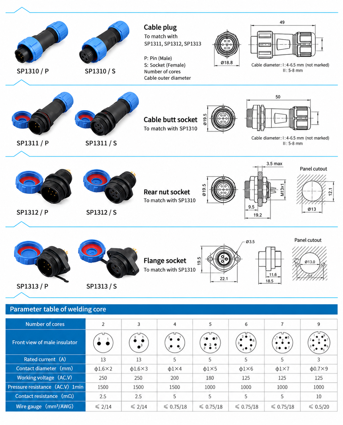
Konnektör Gövde Boyutları
| Format | Model ailesi | Drawing dimensions |
|---|---|---|
| Kablo fişi | SP1310 | 49.0 mm length; Ø18.8 mm front diameter |
| Inline cable socket | SP1311 | 50.0 mm length; Ø19.5 mm front diameter |
| Rear-nut panel socket | SP1312 | 19.2 mm length; Ø19.5 mm front diameter; M13 × 1 mounting thread |
| Flange socket | SP1313 | 18.5 mm length; 19.5 mm front height; Ø3.5 mm mounting holes; 22.1 mm body mounting-hole pitch |
Panel Mounting Dimensions
| Format | Panel opening | Montaj detayları |
|---|---|---|
| Rear-nut panel socket | Ø13.0 mm opening with 12.1 mm across flats | Maximum panel thickness: 3.5 mm |
| Flange socket | Ø13.0 mm centre opening | Two Ø3.5 mm holes at 22.0 mm pitch |
Body dimensions and panel openings are listed separately. The flange body drawing gives 22.1 mm mounting-hole pitch, while the panel opening drawing gives 22.0 mm; use the panel opening dimensions when planning the panel.
Konnektör Formatları ve Model Tanımlamaları
| Format | Pin-contact designation | Socket-contact designation | Matching format |
|---|---|---|---|
| Kablo fişi | SP1310/P | SP1310/S | Mates with SP1311, SP1312 or SP1313 of the corresponding contact arrangement |
| Inline cable socket | SP1311/P | SP1311/S | Cable-to-cable connection with SP1310 |
| Rear-nut panel socket | SP1312/P | SP1312/S | Panel connection with SP1310 |
| Flange socket | SP1313/P | SP1313/S | Flange-mounted panel connection with SP1310 |
P identifies pin contacts and S identifies socket contacts. Both contact types are offered in each listed body format; choose complementary contacts and the same contact count for the mating pair. The designations above identify the connector format; specify the contact count separately in the enquiry.
Seçim Kılavuzu
- Select SP13 and the required contact count.
- Check the rated current, AC working voltage and conductor cross-section together in the electrical table.
- Choose a cable-to-cable or cable-to-panel connection and select the corresponding body format.
- Select Type I for 4–6.5 mm cable or Type II for 5–8 mm cable. Type I is unmarked in the catalogue designation; specify the seal size explicitly when ordering.
- Specify complementary P and S contacts and check the applicable body and panel dimensions.
Sipariş Bilgileri
For a quotation, provide the SP13 model family, contact count, P or S contact type, cable outer diameter, mating connector format and required quantity. For panel sockets, include the panel thickness and mounting format.