
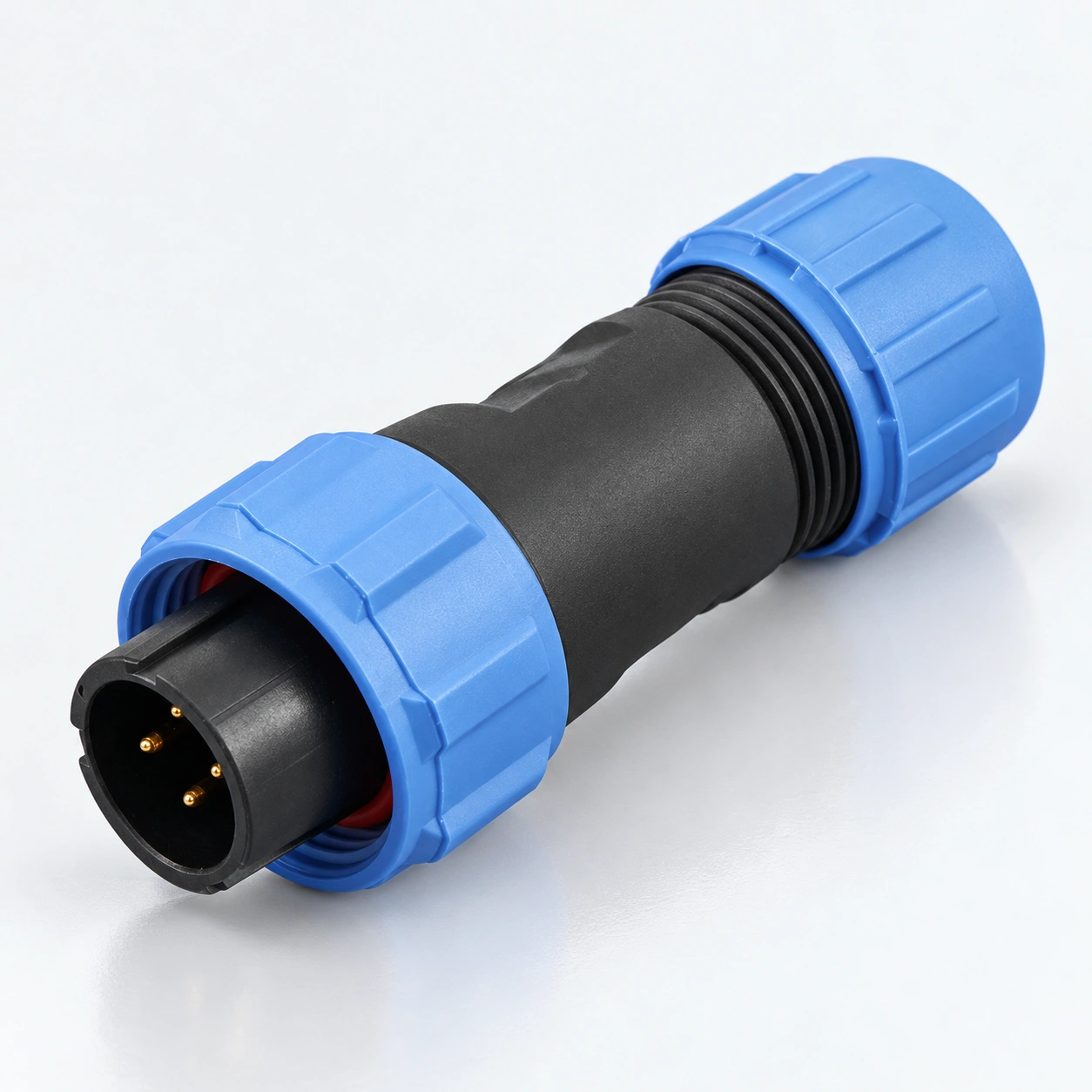
SP13 IP68 Waterproof Circular Connectors
YOCL ELECTRIC SP13 waterproof circular connectors combine threaded locking with solder termination for cable and panel connections.
- Contacts: 2 / 3 / 4 / 5 / 6 / 7 / 9.
- Protection: IP68.
- Cable diameter: 4–6.5 mm or 5–8 mm.
- Formats: cable plug, inline cable socket, rear-nut panel socket and flange socket.
- Ratings: select current and AC working voltage by contact count in the specification table.
Overview
YOCL ELECTRIC SP13 waterproof circular connectors provide threaded locking and solder termination for detachable cable and panel connections. The family uses gold-plated copper contacts, thermoplastic housings and PPS insulators, with an IP68 protection rating.
The series covers seven contact arrangements: 2, 3, 4, 5, 6, 7 and 9 contacts. The 2- and 3-contact configurations are rated at 13 A and 250 V AC; higher contact counts have their own ratings as shown below. Two cable seal sizes accommodate 4–6.5 mm or 5–8 mm cable diameters.
Features
- Threaded locking: a screw coupling retains the mating connector halves.
- Contact options: 2 / 3 / 4 / 5 / 6 / 7 / 9 contacts, with electrical ratings selected by contact arrangement.
- Gold-plated copper contacts: solder termination for the configurations listed on this page.
- Cable and panel formats: cable plug, inline cable socket, rear-nut panel socket and flange socket.
- Cable seal selection: 4–6.5 mm or 5–8 mm cable diameter.
- Temperature range: −40°C to +85°C, with 500 mating cycles listed for the series.
Technical Specifications
Common Specifications
| Parameter | Specification |
|---|---|
| Brand | YOCL ELECTRIC |
| Series | SP13 |
| Contact arrangements | 2 / 3 / 4 / 5 / 6 / 7 / 9 contacts |
| Coupling | Threaded locking |
| Termination | Solder |
| Housing material | Thermoplastic PC / PA66 |
| Housing material fire rating | V-0 |
| Insulator material | Thermoplastic PPS |
| Contact material | Gold-plated copper |
| Protection rating | IP68 |
| Temperature range | −40°C to +85°C |
| Mating cycles | 500 |
| Insulation resistance | 2000 MΩ |
| Type I cable seal | 4–6.5 mm; Type I is not marked in the model designation |
| Type II cable seal | 5–8 mm |
Electrical Ratings by Contact Arrangement
| Contacts | Rated current | Working voltage | Contact diameter × quantity | Maximum conductor cross-section | Catalogue AWG reference |
|---|---|---|---|---|---|
| 2 | 13 A | 250 V AC | Ø1.6 mm × 2 | ≤2.0 mm² | 14 |
| 3 | 13 A | 250 V AC | Ø1.6 mm × 3 | ≤2.0 mm² | 14 |
| 4 | 5 A | 200 V AC | Ø1.0 mm × 4 | ≤0.75 mm² | 18 |
| 5 | 5 A | 180 V AC | Ø1.0 mm × 5 | ≤0.75 mm² | 18 |
| 6 | 5 A | 125 V AC | Ø1.0 mm × 6 | ≤0.75 mm² | 18 |
| 7 | 5 A | 125 V AC | Ø1.0 mm × 7 | ≤0.75 mm² | 18 |
| 9 | 3 A | 125 V AC | Ø0.7 mm × 9 | ≤0.5 mm² | 20 |
Choose the current, working voltage and conductor limit from the same row. The AWG values are the paired references supplied with the metric wire sizes; the conductor limit is expressed in mm².
Dielectric Withstand and Contact Resistance
| Contacts | Dielectric withstand voltage | Contact resistance |
|---|---|---|
| 2 | 1500 V AC for 1 minute | 2.5 mΩ |
| 3 | 1500 V AC for 1 minute | 2.5 mΩ |
| 4 | 1500 V AC for 1 minute | 5 mΩ |
| 5 | 1000 V AC for 1 minute | 5 mΩ |
| 6 | 1000 V AC for 1 minute | 5 mΩ |
| 7 | 1000 V AC for 1 minute | 5 mΩ |
| 9 | 1000 V AC for 1 minute | 10 mΩ |
The dielectric withstand value is a one-minute test voltage, separate from the working voltage.
Dimension
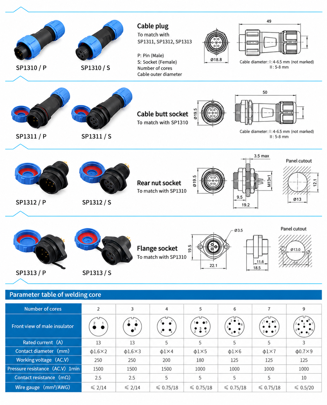
Connector Body Dimensions
| Format | Model family | Drawing dimensions |
|---|---|---|
| Cable plug | SP1310 | 49.0 mm length; Ø18.8 mm front diameter |
| Inline cable socket | SP1311 | 50.0 mm length; Ø19.5 mm front diameter |
| Rear-nut panel socket | SP1312 | 19.2 mm length; Ø19.5 mm front diameter; M13 × 1 mounting thread |
| Flange socket | SP1313 | 18.5 mm length; 19.5 mm front height; Ø3.5 mm mounting holes; 22.1 mm body mounting-hole pitch |
Panel Mounting Dimensions
| Format | Panel opening | Mounting details |
|---|---|---|
| Rear-nut panel socket | Ø13.0 mm opening with 12.1 mm across flats | Maximum panel thickness: 3.5 mm |
| Flange socket | Ø13.0 mm centre opening | Two Ø3.5 mm holes at 22.0 mm pitch |
Body dimensions and panel openings are listed separately. The flange body drawing gives 22.1 mm mounting-hole pitch, while the panel opening drawing gives 22.0 mm; use the panel opening dimensions when planning the panel.
Connector Formats and Model Designations
| Format | Pin-contact designation | Socket-contact designation | Matching format |
|---|---|---|---|
| Cable plug | SP1310/P | SP1310/S | Mates with SP1311, SP1312 or SP1313 of the corresponding contact arrangement |
| Inline cable socket | SP1311/P | SP1311/S | Cable-to-cable connection with SP1310 |
| Rear-nut panel socket | SP1312/P | SP1312/S | Panel connection with SP1310 |
| Flange socket | SP1313/P | SP1313/S | Flange-mounted panel connection with SP1310 |
P identifies pin contacts and S identifies socket contacts. Both contact types are offered in each listed body format; choose complementary contacts and the same contact count for the mating pair. The designations above identify the connector format; specify the contact count separately in the enquiry.
Selection Guide
- Select SP13 and the required contact count.
- Check the rated current, AC working voltage and conductor cross-section together in the electrical table.
- Choose a cable-to-cable or cable-to-panel connection and select the corresponding body format.
- Select Type I for 4–6.5 mm cable or Type II for 5–8 mm cable. Type I is unmarked in the catalogue designation; specify the seal size explicitly when ordering.
- Specify complementary P and S contacts and check the applicable body and panel dimensions.
Ordering Information
For a quotation, provide the SP13 model family, contact count, P or S contact type, cable outer diameter, mating connector format and required quantity. For panel sockets, include the panel thickness and mounting format.