
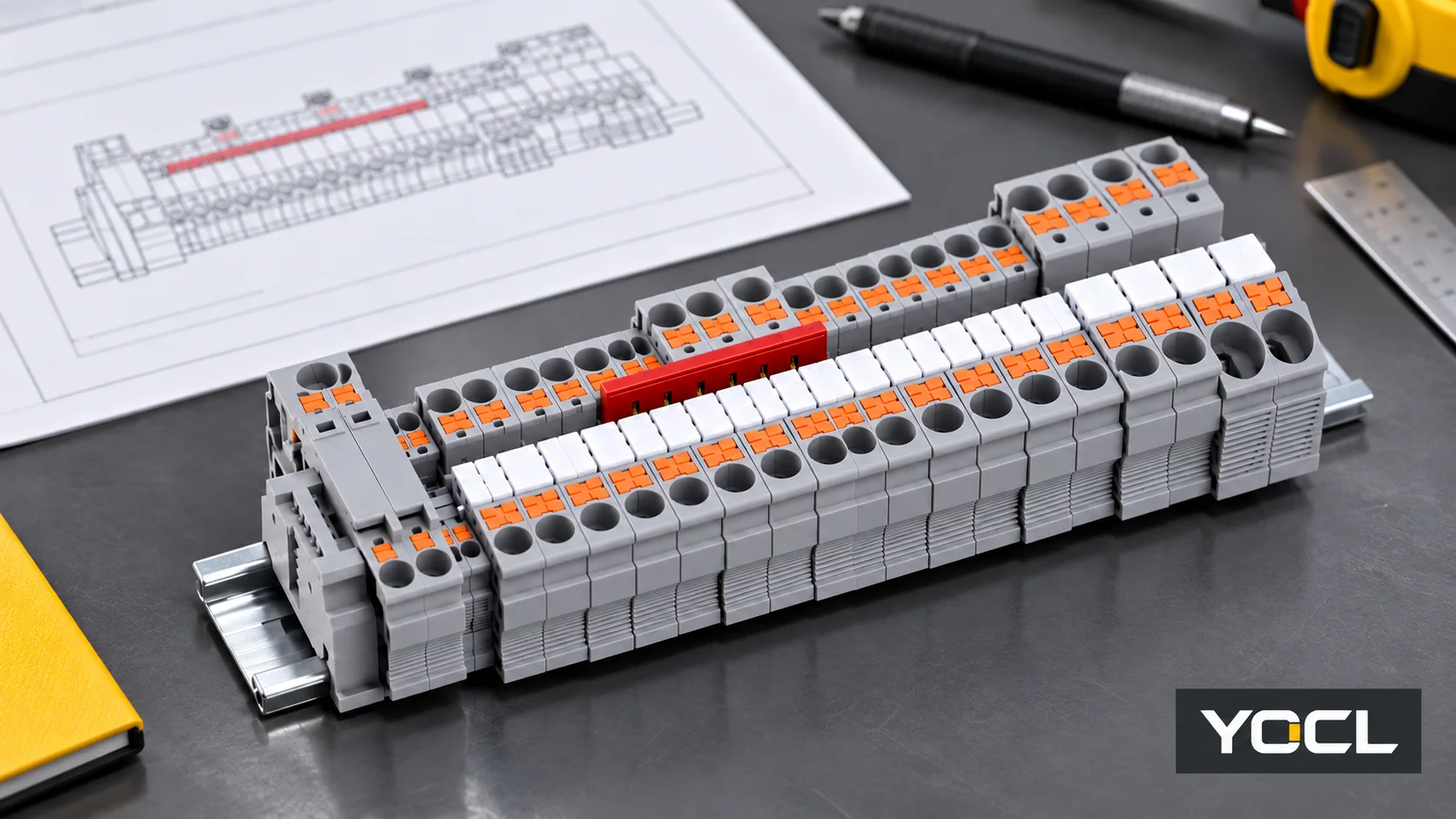
Untuk mengatur strip terminal rel DIN, mulailah dengan gambar sirkuit yang disetujui dan jadwal terminal. Tempatkan terminal dalam urutan yang dapat dilacak, identifikasi terminal mana yang ditujukan untuk berbagi potensial, dan tentukan jumper yang kompatibel untuk setiap grup. Kemudian tentukan lokasi end stop, pelat ujung dan partisi yang diperlukan, serta penanda. Periksa baris yang telah dirakit terhadap catatan tersebut sebelum peralatan dikembalikan ke layanan.
Kedekatan fisik bukan merupakan izin untuk menjembatani terminal. Jumper menciptakan koneksi listrik; end stop memberikan penahan mekanis. Fungsinya harus diperiksa secara terpisah, menggunakan instruksi terminal dan aksesori yang dipilih.
Panduan ini menjelaskan metode perencanaan dan verifikasi, bukan diagram pengkabelan atau pengganti instruksi produsen peralatan. Pekerjaan pada peralatan listrik harus dilakukan oleh personel yang kompeten. Sebelum menyentuh atau mengubah baris, identifikasi setiap sumber pasokan dan energi tersimpan, isolasi dan amankan peralatan, serta verifikasi bahwa area kerja dalam keadaan mati sesuai prosedur lokasi. Lindungi dari bagian aktif di sekitarnya. UK Health and Safety Executive’s HSG85, paragraf 53–59, menjelaskan tindakan pencegahan ini; aturan setempat dan prosedur peralatan juga berlaku.
Gather the Documents Before Arranging the Row
A useful starting pack has the approved schematic, terminal plan, enclosure or rail layout, terminal and accessory part numbers, current and voltage requirements, identification convention and the applicable assembly instructions. Confirm who controls changes to the drawings. For a modification, compare those documents with the actual equipment; do not assume an existing jumper matches the latest drawing.
The terminal block overview explains the basic interfaces. If the terminal itself is not yet selected, first use the DIN rail terminal block selection guide to establish the conductor and connection requirements. A tidy layout cannot correct an unsuitable terminal or conductor combination.
milik YOCL PT series product information lists end covers, end stops, partition plates, markers and bridges as terminal-system accessories. The UK series information also describes model-specific jumper and end-plate options. These are product-family descriptions: confirm the exact terminal and accessory combination before ordering or assembling it.
1. Make a Terminal and Circuit Schedule
Give each connection point an identifier that can be traced to the schematic. Record its function, intended electrical group, terminal model, conductor destination and relevant accessory. The group field identifies which points are deliberately common; it is not inferred from the position of a terminal on the rail.
The example below is a planning illustration, not an approved circuit or a YOCL wiring diagram. A dan B are different intended potentials. The terminal and bridge part numbers, current values and protection details remain to be established for the actual project.
| Posisi | Intended function | Electrical group | Planned relationship | Record before assembly |
|---|---|---|---|---|
| X1:01 | Feed point | A | Common with X1:02 and X1:03 only if approved by the circuit design | Terminal and bridge part numbers; feed and branch duties |
| X1:02–03 | Two outgoing points | A | Same approved group as X1:01 | Bridge positions and each conductor destination |
| X1:04–05 | Separate circuit | B | A separate group; no bridge from group A. Internal bridging only if specified | Its own circuit, terminal and accessory information |
| Row ends | Mechanical boundaries | Tidak ada | End stops at the positions required by the selected assembly | Stop model, rail fit and installation instructions |
This record gives the reviewer two different questions: where does a component sit? dan what is it allowed to connect? If a schematic revision changes the second answer, update the schedule before touching the bridge.
2. Lay Out Terminals by Circuit and Service Access
Arrange the planned points in a sequence that makes the drawings and labels easy to follow. Keep each intended common group identifiable and show the boundary between separate circuits on the layout. Include protective-earth, neutral, live or control functions only as identified by the approved design; colour and position alone do not establish a connection.
Check the available rail length against the actual widths of the selected terminals, required covers, partitions and stops. Also allow for the space needed to access the clamps, markers, jumpers and mounting hardware, and for the conductor routes and enclosure interfaces. Use the exact equipment and accessory drawings rather than a universal spacing allowance. Where the rail profile itself is uncertain, the TS35 DIN rail dimensions guide helps identify the profile; compatibility still depends on each component’s mounting specification.
Before assembly, review the row from both directions: can a technician follow each label back to the schematic, and can the specified parts be fitted and serviced within the enclosure? If the schedule fits on paper but blocks access to a clamp or stop, revise the layout before installing it.
3. Specify Each Jumper as an Electrical Connection
For every intended common group, record the exact terminal models and positions, jumper part number and permitted arrangement. Check the manufacturer’s instructions for the bridge channel, number of poles, insertion or fastening method, compatible end treatments and any restrictions. A bridge that appears to fit is not proof of compatibility. Do not cut, modify, combine or bridge across unlike terminals unless the applicable instructions explicitly permit that configuration.
Trace the complete current path: the feed, the part of the jumper carrying the combined current, each branch and the terminal connections. The allowable duty must be established from the relevant component and assembly documentation under the actual conditions. A terminal’s individual rating alone does not establish the rating of an arbitrary bridge arrangement. For symptoms and diagnostic checks, see terminal block overheating.
In the example, the layout record would show an approved bridge only for group A if the selected parts and circuit design permit it. Group B needs its own documented relationship. Never extend the A bridge into B merely because X1:04 is next to X1:03. If the intended electrical separation cannot be confirmed, stop and refer the drawing to the responsible designer.
4. Add End Stops, End Plates and Partitions
These parts solve different problems:
| Part | Planning purpose | Check before installation |
|---|---|---|
| End stop / end bracket | Restrains the row mechanically on the rail as specified. | Correct rail and stop model, position, access and fastening method. It is not an electrical barrier. |
| End plate / end cover | Closes the exposed side of a compatible terminal when that terminal’s design requires it. | Whether the exact end terminal needs a plate and which part is specified. An end stop does not replace it. |
| Pelat partisi | Provides the separation function stated for a particular terminal system and arrangement. | Part number, position and the requirements for the intended circuits. Do not assume every divider provides the required isolation or clearance. |
| Penanda | Connects the physical point or group to the circuit record. | Marking format, legibility, holder compatibility and agreement with the drawing. |
Show the required parts explicitly on the schedule and the physical layout. Some terminals have enclosed housings, while others require an end plate; follow the selected model’s documentation rather than assuming that every row uses the same parts. Similarly, the number, locations and fastening of stops depend on the selected system and installation conditions. Do not use a generic tightening torque.
5. Assemble and Check Against the Schedule
With the work area safely isolated and verified, assemble the specified components using their own instructions and suitable tools. The schedule is a control document, not a replacement for model-specific mounting, conductor preparation or tightening instructions. At each stage, compare the actual part and location with the record; do not force a part that does not fit.
| Check | Expected result | Stop and resolve if… |
|---|---|---|
| Terminal order and labels | Every point matches the latest drawing and destination. | A label, terminal function or conductor destination conflicts with the schedule. |
| Jumper groups | Each approved jumper is the specified part and occupies only the documented positions. | The part, pole count, position or intended potential is uncertain. |
| Mechanical retention | The specified stops and rail-mounted components are installed according to their instructions. | A stop cannot be fitted correctly or the row cannot be restrained as specified. |
| Covers and separation | The specified end plates and partitions are present in their documented positions. | A required part is missing, damaged or has unverified compatibility. |
| Access and condition | Labels, connection points and required operating features remain accessible; components show no visible damage. | The layout obstructs service access or a part is cracked, distorted or otherwise suspect. |
Resolve discrepancies through the equipment owner’s change-control process. If the proposed arrangement cannot be supported by the manufacturer documentation or the approved circuit drawing, do not improvise a substitute. Obtain the missing information or revise the design and schedule.
6. Verify, Record and Restore
Record the final terminal identifiers, actual component and accessory part numbers, jumper positions, drawing revision and any approved deviations. The responsible person should perform the inspections and electrical tests required by the equipment manufacturer, project and local procedures. A visual check and a neat row do not prove correct continuity, insulation, protective-earth effectiveness or the rating of the complete assembly.
Only after the specified checks are complete should authorized personnel restore covers and return the equipment to service under the site’s procedure. If verification fails or an unexpected connection is found, keep the equipment isolated and escalate it for correction and re-verification.
For a YOCL terminal-strip enquiry, provide the terminal series and model, circuit and conductor schedule, rail layout, desired bridge groups, accessory quantities and identification requirements through the DIN rail terminal block product page. Confirm compatibility and application requirements against the returned model documents before assembly.
Referensi
- UK Health and Safety Executive, Electricity at Work: Safe Working Practices (HSG85), paragraphs 53–59, isolation and precautions near live parts.
- YOCL ELECTRIC, Blok Terminal Rel Push-In Seri PT DIN, product information on the series and accessory categories.
- YOCL ELECTRIC, Blok Terminal Rel Sekrup Seri UK DIN, product information on model-specific jumper and end-plate options.