
Conductor & preparation
Specify solid or stranded conductors, cross-section, ferrule use and conductors per connection. Check stripping length and permitted preparation for the exact terminal.
Kontrol kabinetleri ve elektrik panosu kablolaması için DIN ray terminal blokları. PT itmeli, SJ kafes yaylı ve vidalı terminal serilerini, geçişli, çok katlı ve koruyucu toprak seçenekleri dahil karşılaştırın. İletken boyutlarınıza, devre gereksinimlerinize ve ray düzeninize göre bir terminal çizelgesi oluşturun.
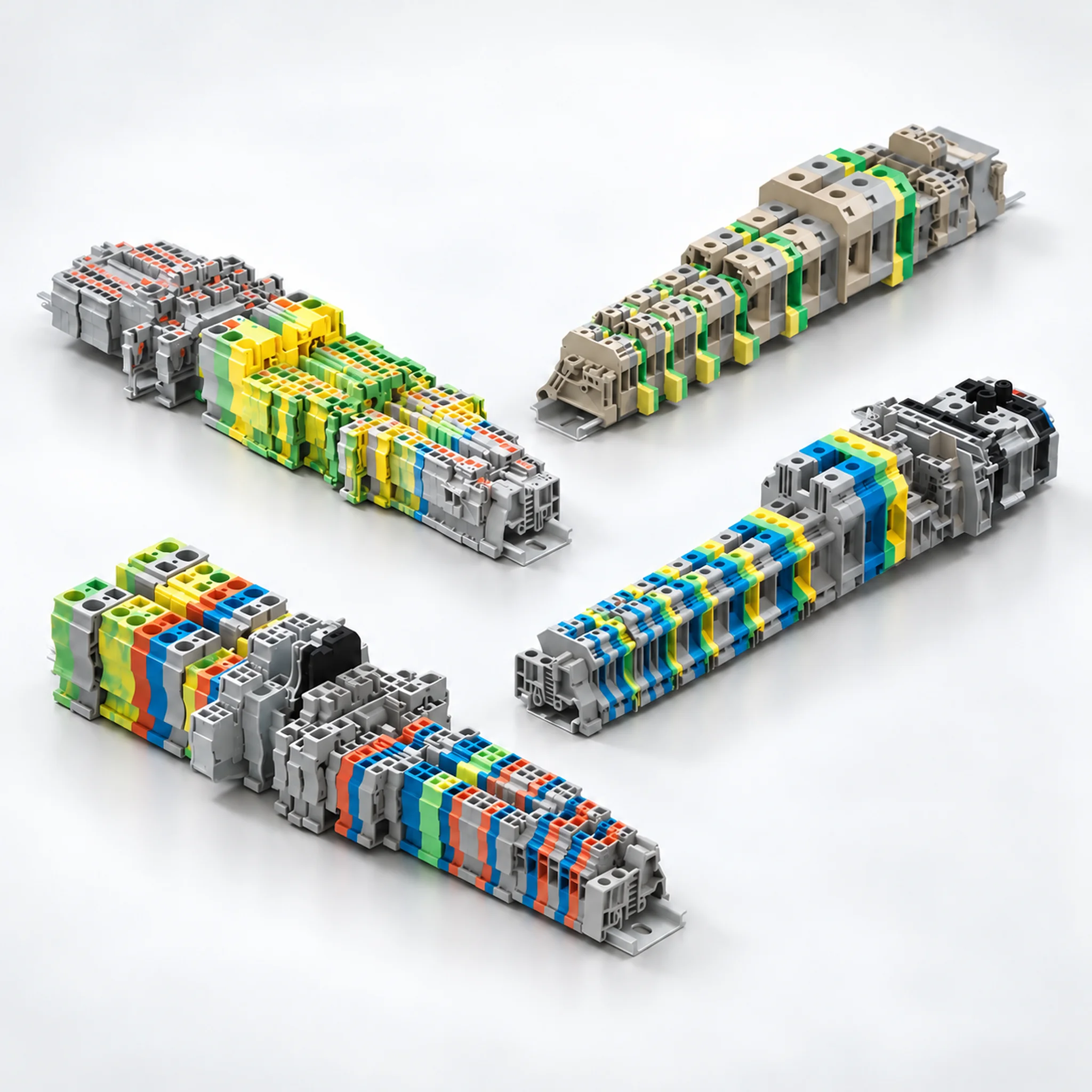
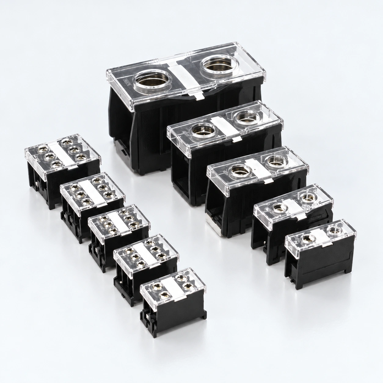
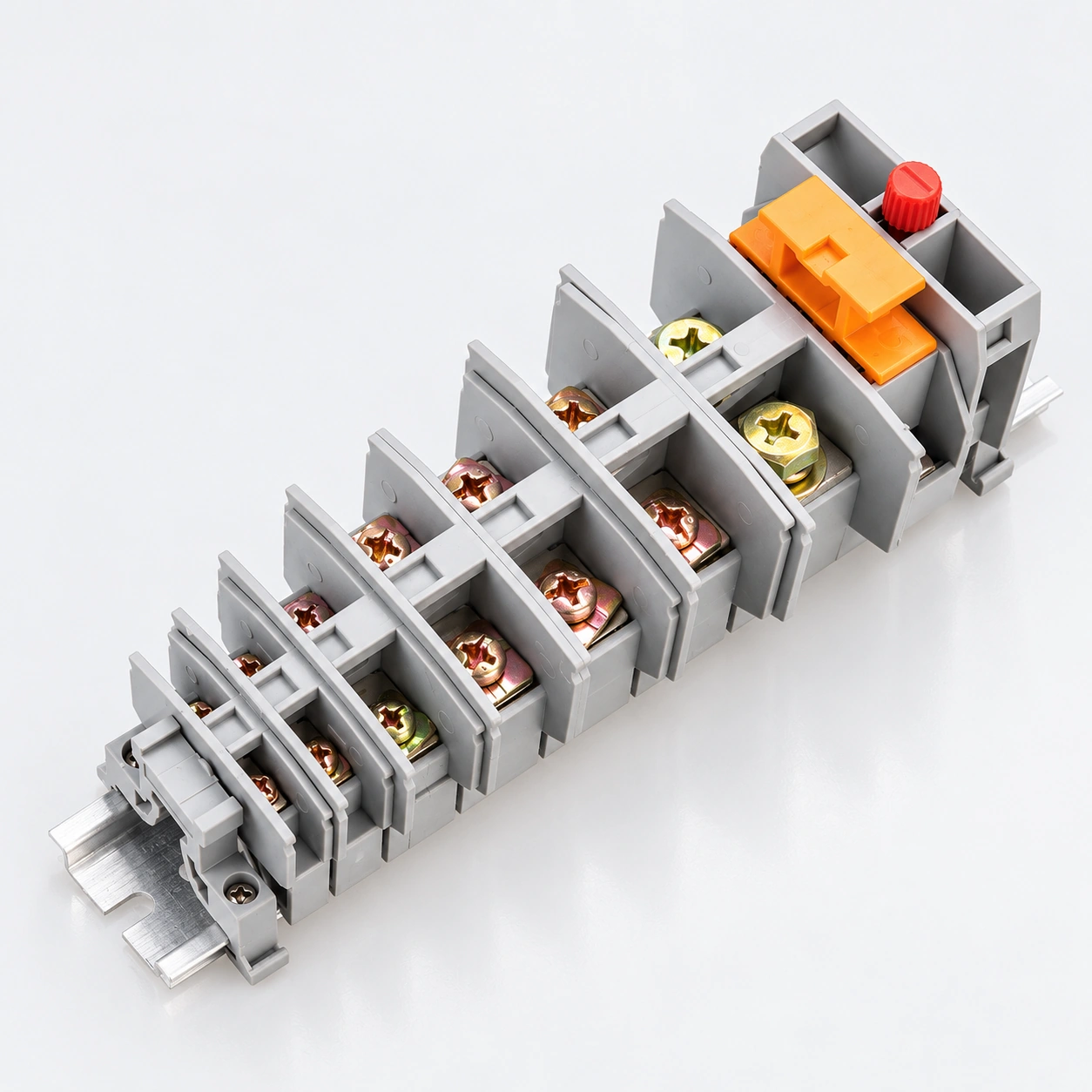
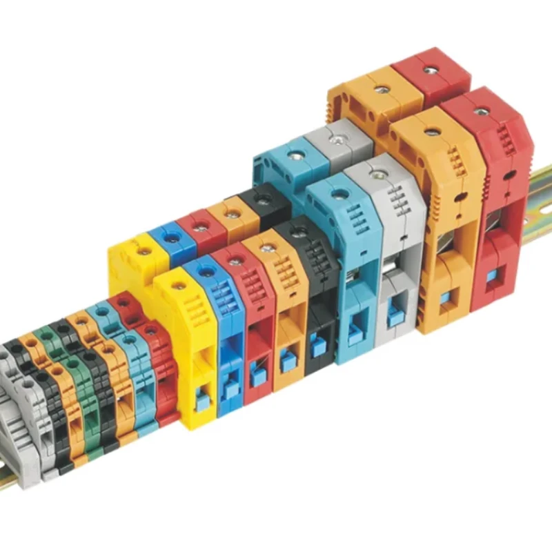
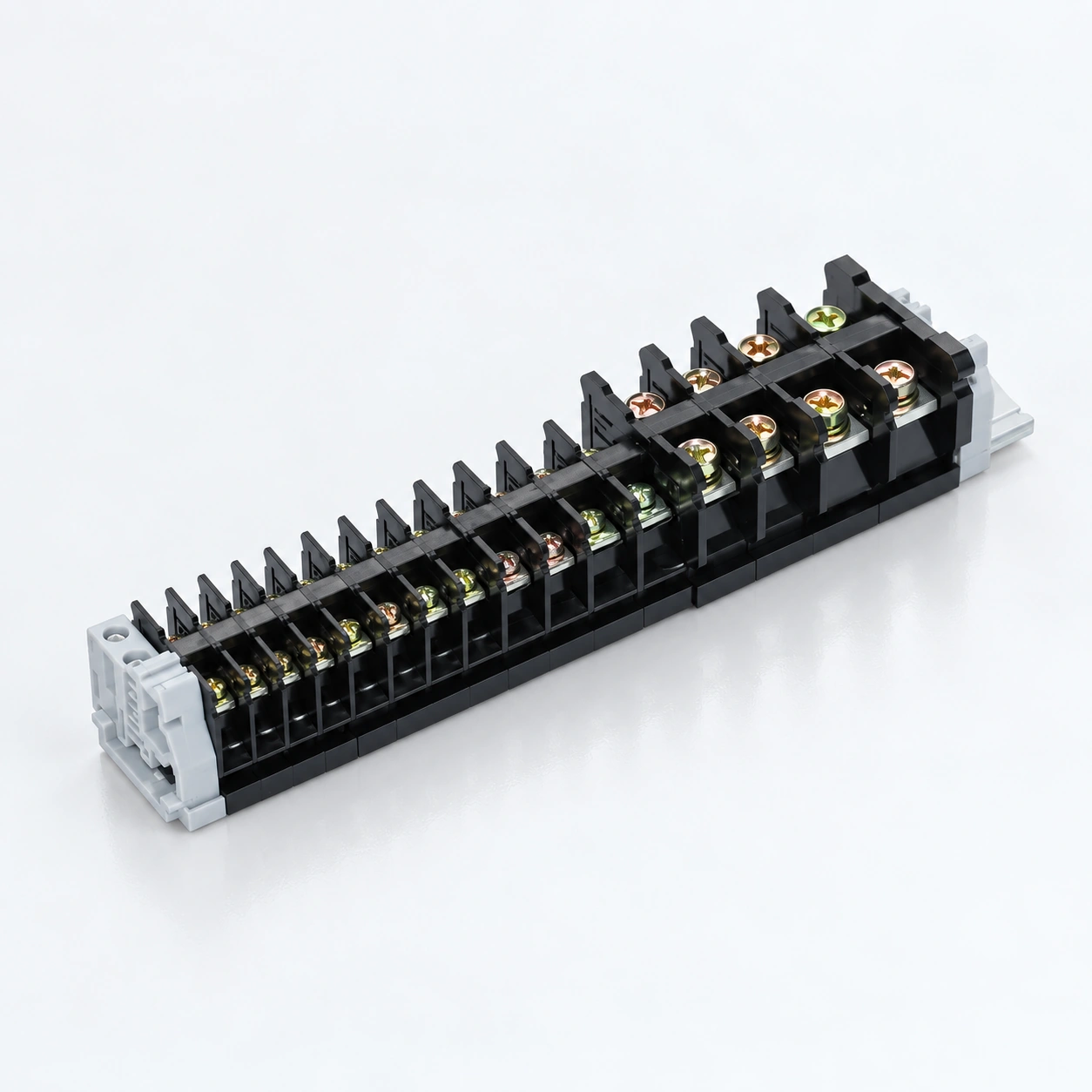
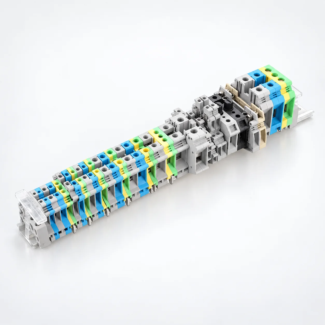
| Yapı | Seçim odak noktası | Seri referansı |
|---|---|---|
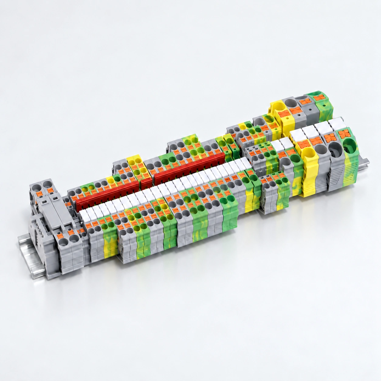
| PT · İtmeli | Standart geçişli, TWIN, QUATTRO, çok katlı ve PE konfigürasyonlarını kapsayan 35 listelenmiş modeller. Uygun masif veya yüksüklü iletkenler için itmeli bağlantı; NS 35 montaj ayağı. | PT serisi |
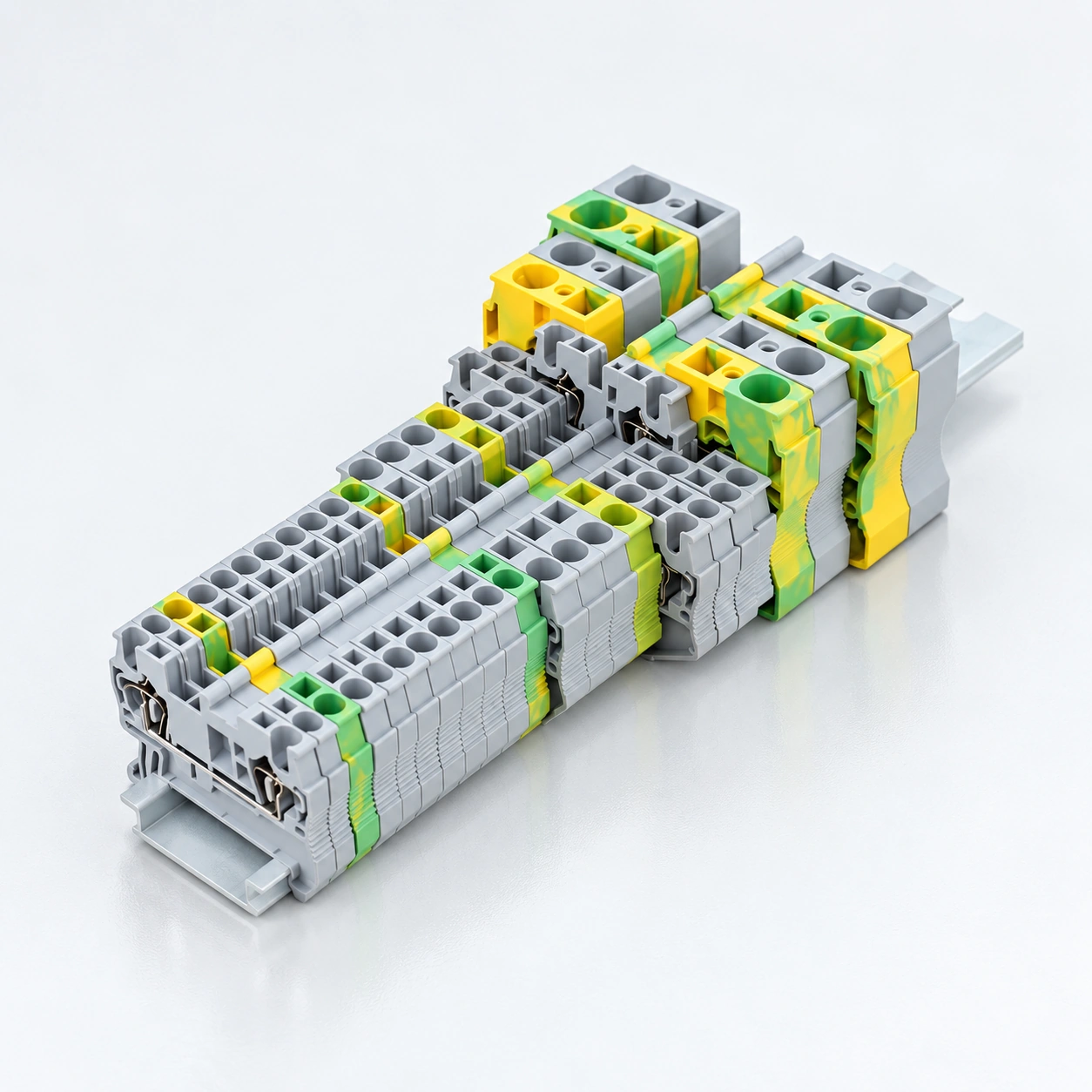
| SJ · Kafes yaylı | 13 listelenen modeller, 1.5 ile 16 mm² arasındaki nominal kesitlere sahiptir. TH35-7.5 / TH35-15 montaj. Elektriksel değerler, listelenen her varyant için değil, sekiz model için belirtilmiştir. | SJ serisi |
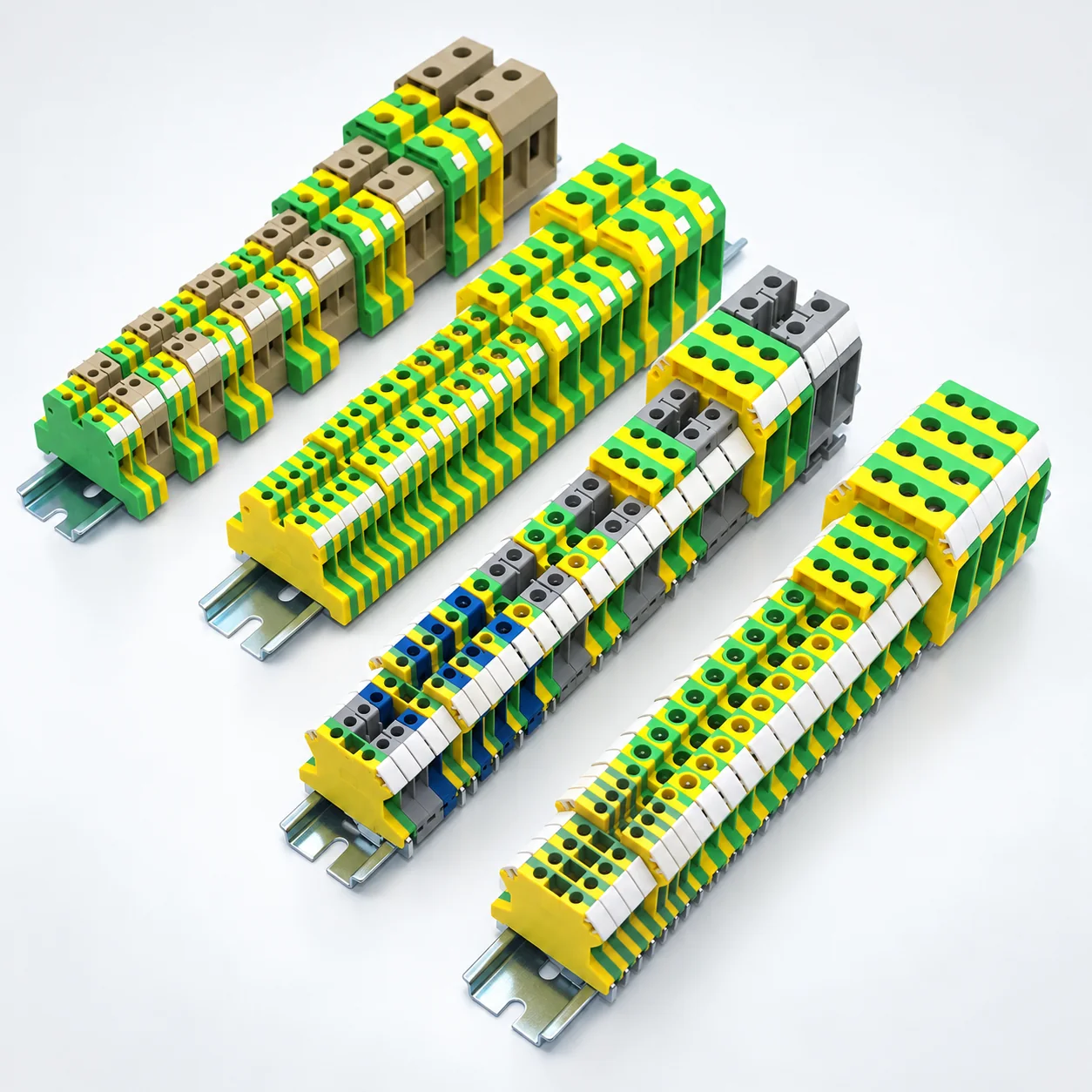
| UK · Vidalı kelepçe | 36 listelenen modeller standart, kompakt, çok seviyeli ve koruyucu toprak terminallerini içerir. Sert/esnek iletken aralıklarını ve modele özel jumper ve uç plaka seçeneklerini kontrol edin. | UK · USLKG PE modelleri |
| SAK · Vidalı kelepçe | Sekiz standart, dört özel işlevli ve altı EK koruyucu toprak modeli. Modele özel iletken aralıkları ve boyutlarına sahip çerçeve tipi vidalı bağlantılar. | SAK / SAK(JXB) · EK |
| JH1A · Vida | Listelenen akımları 17.5–125 A ve 380 V veya 500 V derecelendirmelerine sahip dokuz model. İletken kapasitesini, vida boyutunu ve belirtilen 35 mm veya 28 mm montaj rayını inceleyin. | JH1A serisi |
| MRK · Panel bağlantıları | Listelenen kesitleri 2.5 ila 120 mm² arasında, bireysel akımları 24–269 A ve 750 V veya 1000 V derecelendirmelerine sahip 11 modeller. 35 mm DIN raylarına geçmeli montaj. | MRK serisi |
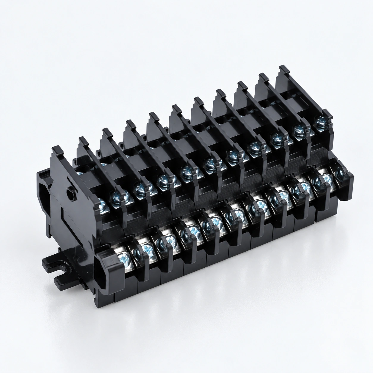
| TBD · Çift katmanlı vida | Paylaşılan bir ayak izi içinde iki kablolama seviyesi. 10, 20 veya 30 A olarak derecelendirilmiş üç model, 600 V'te, 35 mm DIN ray montajı ile. Listelenen standart düzen 10 pozisyona ve uç plakalara sahiptir. | TBD-10A · TBD-20A · TBD-30A |
| TK · Screw | Six models from TK-010 to TK-100 with 10–100 A individual ratings and model-specific conductor sizes spanning 0.75–25 mm². TH35-7.5 mounting; check AC and DC voltage specifications separately. | TK series |
| IN · Screw | Eight models rated 600 V, with individual currents of 20–240 A and wire ranges spanning 0.75–100 mm². Transparent PC covers have tool-access openings. | IN series |
Ranges above summarize different models. Select the conductor capacity, current and voltage from the same product row.
Specify solid or stranded conductors, cross-section, ferrule use and conductors per connection. Check stripping length and permitted preparation for the exact terminal.
Choose push-in, cage spring or screw termination according to the wiring process and selected model. Confirm insertion, release or tightening instructions; do not assume all spring terminals operate identically.
Identify the rail profile and dimensions, terminal width, height and depth. Most listed families include 35 mm mounting options, but JH1A also lists 28 mm rail widths; verify each model.
Distinguish feed-through, PE, multi-level and special-function circuits. Select matching bridges, markers, end plates and end stops, then check model-specific electrical ratings.
Send the terminal series and model, conductor schedule, rail drawing, accessory list and quantities. Include required labels, packing and project documentation.
Bir sorgu hazırlayınSiparişinizi vermeden önce spesifikasyonu ve gerekli kanıtları kabul edin.
Üretimi keşfedinList each terminal model, circuit function, conductor type and size, and quantity. Separate feed-through, protective-earth and special-function positions.
Provide the rail profile, usable rail length and panel-space constraints. Include terminal width, end components and access needed for wiring and maintenance.
List series-compatible bridges, end plates, markers and end stops. Specify circuit identification and bridge positions rather than assuming accessories are universal.
State required model documentation, inspection criteria, label artwork, pack quantities and destination. Confirm sample and supply requirements with the quotation.
OEM & PAKETLEME
Build your din rail terminal blocks order around the selected models, identification and supply requirements.
List each terminal model, circuit function, conductor type and size, and quantity. Separate feed-through, protective-earth and special-function positions.
Parça numaralarını, etiket çizimlerini ve sipariş için gereken herhangi bir parti veya izlenebilirlik bilgilerini sağlayın.
Model başına, bireysel paketler, dış kartonlar ve teslimat destinasyonu başına miktarları belirtin.
They provide organized conductor termination points in control cabinets and electrical panels. The required model depends on the circuit function, wire capacity, electrical ratings, rail interface and installation space.
The PT range lists push-in connection for suitable solid or ferruled conductors. SJ is a cage spring range. Conductor insertion and release procedures depend on the selected mechanism and model; follow its specific instructions rather than treating both names as interchangeable.
No universal rail fit is claimed. PT specifies NS 35; SJ lists TH35-7.5 and TH35-15; TK lists TH35-7.5. JH1A includes 35 mm and 28 mm rail widths. Confirm the rail interface for your exact model.
They serve different circuit functions. PT includes PE configurations, UK includes USLKG protective-earth models, and SAK includes EK models. Review the intended earth connection and mounting requirements separately; do not apply feed-through current or voltage ratings by assumption.
Do not assume compatibility. Match bridges, end plates, markers and fixing accessories to the terminal model and manufacturer drawing. UK product information identifies model-specific jumper and end-plate options.
It depends on the connection mechanism and approved conductor preparation. Provide the wire type, size and ferrule details, and check the selected terminal's instructions and clamping capacity.
No. A material flammability classification is not certification of the complete terminal block. Request model-specific certification or test evidence where your project requires it.
This page focuses on DIN rail terminal blocks. For dedicated incoming-to-branch power connections such as UKK, K and UTJ5, use the separate Power Distribution Blocks range.
Send the terminal schedule, rail layout, bridge positions, circuit labels and quantities for a feasibility review. Assembly, marking, sample and packing options are confirmed for the requested configuration.
Send the terminal series and model, conductor schedule, rail drawing, accessory list and quantities. Include required labels, packing and project documentation. Include the exact model quantities, delivery destination and required documentation.
Parça numaralarınızı, etiket çizimlerinizi, paket miktarlarını ve sevkiyat gereksinimlerinizi gönderin. Talep edilen modeller için fizibilite, numune gereksinimleri, minimum miktarlar ve teslim süresi onaylanır.