
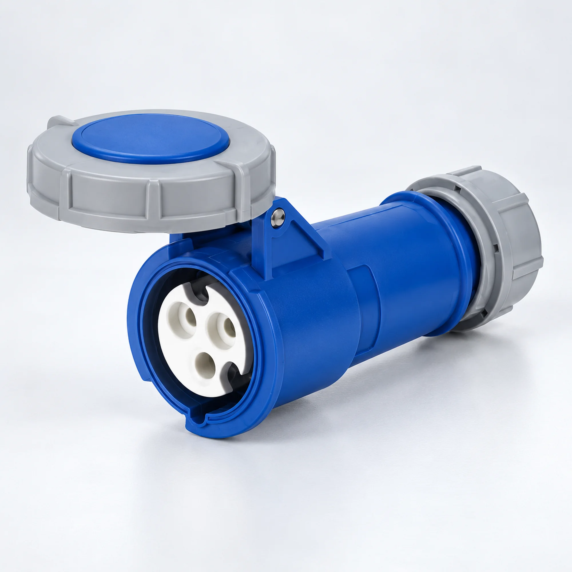
IP44 Endüstriyel Kablo Kuplörleri
YOCL ELEKTRİK IP44 kablo ucu bağlantıları için endüstriyel kablo kuplajları, farklı gövde tasarımları ve eksiksiz NM model seçim tabloları ile.
- Anma akımları: 16 A ve 32 A.
- Kontak düzenleri: 2P+E, 3P+E ve 3P+N+E.
- Modele bağlı olarak 4h, 6h ve seçilmiş 9h toprak kontak düzenleri.
- Ön kapaklı dişi kablo konektörü.
- Tam model kodu ile voltajı, iletken kapasitesini ve boyutları seçin.
Genel Bakış
YOCL ELEKTRİK IP44 endüstriyel kablo kuplajları, endüstriyel kablo bağlantıları için dişi kablo konektörleridir. Bu aile, aşağıda listelenen gerçek 16 A ve 32 A modellerini, 2P+E, 3P+E ve 3P+N+E kontak düzenlemeleriyle bir araya getirir. Her modelin kendi voltajı, toprak kontak saat konumu ve gövde tasarımı vardır.
Konektör ucunda dişi kontaklar ve koruyucu bir ön kapak bulunur; arka giriş besleme kablosunu kabul eder. H-tasarım, K-tasarım, beyaz arka gövde ve özel saat konumu versiyonları, gövde fotoğrafının ve boyut verilerinin doğru konektörle eşleştirilebilmesi için ayrı model grupları olarak kalır.
Özellikler
- Listelenen modeller için IP44 koruma derecesi.
- Kablo konektörü ucu için dişi kontaklar ve koruyucu kapak.
- Anma akımı seçenekleri: 16 A ve 32 A; gerçek kombinasyonlar model tablolarıyla tanımlanır.
- 2P+E, 3P+E ve 3P+N+E versiyonları ayrı ayrı tanımlanır.
- Toprak kontak düzenleri: Adlandırılan modele göre 4h, 6h ve seçilmiş 9h.
- Ayrı muhafaza grupları, her modelin iletken kapasitesini ve boyut verilerini korur.
Teknik Özellikler
| Parametre | Teknik Özellikler |
|---|---|
| Marka | YOCL ELEKTRİK |
| Ürün tipi | Dişi kablo konektörleri |
| Montaj | Kabloya monte |
| Koruma sınıfı | IP44 |
| Anma akımları | 16 A ve 32 A |
| Kontak düzenlemeleri | 2P+E (3 kontak); 3P+E (4 kontak); 3P+N+E (5 kontak) |
| Toprak-temas konumları | 4h, 6h ve seçilmiş 9h |
| Voltaj yapılandırmaları | Bireysel model satırlarına bakınız; eşleştirilmiş beş kontak değerleri listelendiği gibi korunur. |
| İletken kapasiteleri | Model-specific values in mm²; see the selection tables. |
| Housing designs | See the separate model groups below. |
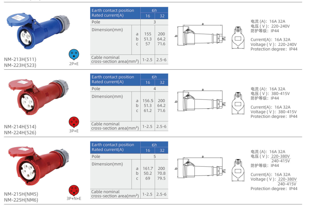
H gövde tasarımı — 16 / 32 A
| Model | Printed reference | Akım (A) | Kontaklar | Voltaj (V) | Clock | Conductor capacity (mm²) | Body color |
|---|---|---|---|---|---|---|---|
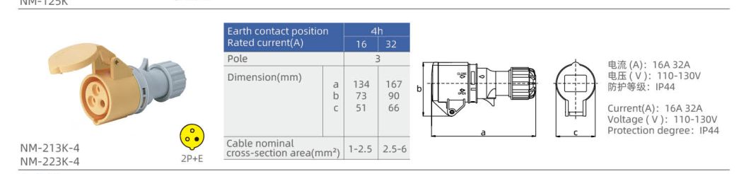
| NM-213H-4 | 511 | 16 | 2P+E | 110–130 | 4h | 1–2.5 | Sarı |
| NM-223H-4 | 523 | 32 | 2P+E | 110–130 | 4h | 2.5–6 | Sarı |
| NM-213H | 511 | 16 | 2P+E | 220–240 | 6h | 1–2.5 | Mavi |
| NM-223H | 523 | 32 | 2P+E | 220–240 | 6h | 2.5–6 | Mavi |
| NM-214H | 514 | 16 | 3P+E | 380–415 | 6h | 1–2.5 | Kırmızı |
| NM-224H | 526 | 32 | 3P+E | 380–415 | 6h | 2.5–6 | Kırmızı |
| NM-215H | NM5 | 16 | 3P+N+E | 220–380 / 240–415 | 6h | 1–2.5 | Kırmızı |
| NM-225H | NM6 | 32 | 3P+N+E | 220–380 / 240–415 | 6h | 2.5–6 | Kırmızı |
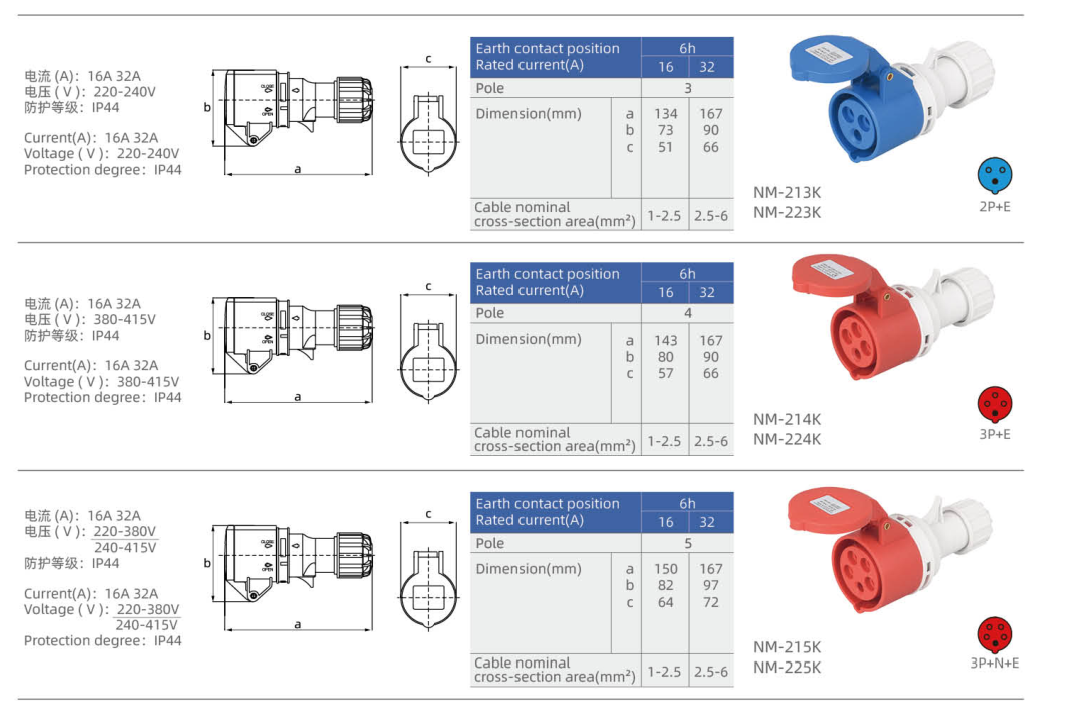
K gövde tasarımı — 16 / 32 A
| Model | Akım (A) | Kontaklar | Voltaj (V) | Clock | Conductor capacity (mm²) | Body color |
|---|---|---|---|---|---|---|
| NM-213K-4 | 16 | 2P+E | 110–130 | 4h | 1–2.5 | Sarı |
| NM-223K-4 | 32 | 2P+E | 110–130 | 4h | 2.5–6 | Sarı |
| NM-213K | 16 | 2P+E | 220–240 | 6h | 1–2.5 | Mavi |
| NM-223K | 32 | 2P+E | 220–240 | 6h | 2.5–6 | Mavi |
| NM-214K | 16 | 3P+E | 380–415 | 6h | 1–2.5 | Kırmızı |
| NM-224K | 32 | 3P+E | 380–415 | 6h | 2.5–6 | Kırmızı |
| NM-215K | 16 | 3P+N+E | 220–380 / 240–415 | 6h | 1–2.5 | Kırmızı |
| NM-225K | 32 | 3P+N+E | 220–380 / 240–415 | 6h | 2.5–6 | Kırmızı |
Beyaz arka gövde tasarımları — 16 / 32 A
| Model | Akım (A) | Kontaklar | Voltaj (V) | Clock | Conductor capacity (mm²) | Body color |
|---|---|---|---|---|---|---|
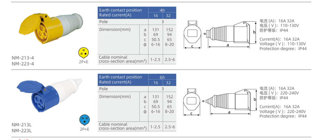
| NM-213-4 | 16 | 2P+E | 110–130 | 4h | 1–2.5 | Sarı |
| NM-223-4 | 32 | 2P+E | 110–130 | 4h | 2.5–6 | Sarı |
| NM-213L | 16 | 2P+E | 220–240 | 6h | 1–2.5 | Mavi |
| NM-223L | 32 | 2P+E | 220–240 | 6h | 2.5–6 | Mavi |
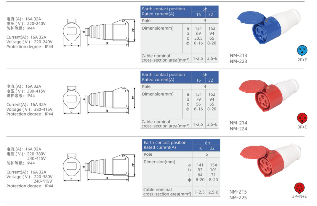
| NM-213 | 16 | 2P+E | 220–240 | 6h | 1–2.5 | Mavi |
| NM-223 | 32 | 2P+E | 220–240 | 6h | 2.5–6 | Mavi |
| NM-214 | 16 | 3P+E | 380–415 | 6h | 1–2.5 | Kırmızı |
| NM-224 | 32 | 3P+E | 380–415 | 6h | 2.5–6 | Kırmızı |
| NM-215 | 16 | 3P+N+E | 220–380 / 240–415 | 6h | 1–2.5 | Kırmızı |
| NM-225 | 32 | 3P+N+E | 220–380 / 240–415 | 6h | 2.5–6 | Kırmızı |
Özel 9h kontak düzenleri — 16 / 32 A
These 9h models use the particular voltage and contact layouts shown below. Their conductor capacities and dimensions are not extended from the ordinary models.
| Model | Akım (A) | Kontaklar | Voltaj (V) | Clock | Conductor capacity (mm²) | Body color |
|---|---|---|---|---|---|---|
| NM-213L-9 | 16 | 2P+E | 380–415 | 9h | — | Kırmızı |
| NM-223L-9 | 32 | 2P+E | 380–415 | 9h | — | Kırmızı |
| NM-214L-9 | 16 | 3P+E | 220–240 | 9h | — | Mavi |
| NM-224L-9 | 32 | 3P+E | 220–240 | 9h | — | Mavi |
Boyut
The symbols below reproduce each housing group’s dimensional table in millimetres. Letter meanings differ between drawings; a repeated symbol does not define one common dimension across all groups. Match the full model code and housing group before using a drawing.
H gövde tasarımı — 16 / 32 A
| Model | Drawing/table dimensions (mm) |
|---|---|
| NM-213H-4 | a = 155; b = 51.3; c = 57 |
| NM-223H-4 | a = 200; b = 64.2; c = 71.6 |
| NM-213H | a = 155; b = 51.3; c = 57 |
| NM-223H | a = 200; b = 64.2; c = 71.6 |
| NM-214H | a = 156.5; b = 51.3; c = 61.2 |
| NM-224H | a = 200; b = 64.2; c = 71.6 |
| NM-215H | a = 161.7; b = 50.2; c = 69 |
| NM-225H | a = 200; b = 70.8; c = 79.5 |
K gövde tasarımı — 16 / 32 A
| Model | Drawing/table dimensions (mm) |
|---|---|
| NM-213K-4 | a = 134; b = 73; c = 51 |
| NM-223K-4 | a = 167; b = 90; c = 66 |
| NM-213K | a = 134; b = 73; c = 51 |
| NM-223K | a = 167; b = 90; c = 66 |
| NM-214K | a = 143; b = 80; c = 57 |
| NM-224K | a = 167; b = 90; c = 66 |
| NM-215K | a = 150; b = 82; c = 64 |
| NM-225K | a = 167; b = 97; c = 72 |
Beyaz arka gövde tasarımları — 16 / 32 A
| Model | Drawing/table dimensions (mm) |
|---|---|
| NM-213-4 | a = 131; b = 69; c = 50.5; φ = 6–16 |
| NM-223-4 | a = 152; b = 94; c = 65; φ = 8–20 |
| NM-213L | a = 131; b = 69; c = 50.5; φ = 6–16 |
| NM-223L | a = 152; b = 94; c = 65; φ = 8–20 |
| NM-213 | a = 131; b = 69; c = 50.5; φ = 6–16 |
| NM-223 | a = 152; b = 94; c = 65; φ = 8–20 |
| NM-214 | a = 131; b = 79; c = 56; φ = 6–16 |
| NM-224 | a = 152; b = 94; c = 65; φ = 8–20 |
| NM-215 | a = 141; b = 93; c = 64; φ = 8–20 |
| NM-225 | a = 154; b = 101; c = 71; φ = 8–20 |
Seçim Kılavuzu
Choose a female cable coupler when the mating connection is made at the end of a cable. A wall-mounted socket or an appliance inlet belongs to a different mounting and contact family.
Select the current rating, contact arrangement, rated voltage, earth-contact clock position and IP rating together from one actual model row. Body color alone is insufficient: the special clock-position groups include different voltage/contact combinations from the ordinary groups.
Keep the complete suffix when selecting the housing version. Models that share an electrical rating may have different lengths, cable-entry dimensions or body shapes. Conductor capacity is a cross-sectional range in mm² and must not be confused with a cable-entry dimension in mm.
For five-contact models, the table preserves the paired 220–380 / 240–415 V notation. It does not create an additional arbitrary voltage combination. A dash in the capacity column means that the particular row supplies no confirmed value.
Sipariş Bilgileri
When enquiring about YOCL ELECTRIC IP44 industrial cable couplers, provide the full model code, quantity, current rating, contact arrangement, rated voltage, clock position and the required housing design. Include the conductor cross-section and cable outside diameter so that the cable entry and terminal range can be checked for that specific model.
Printed secondary references identify the catalogue entries where shown; they do not create extra model options or replace the full NM model code.