
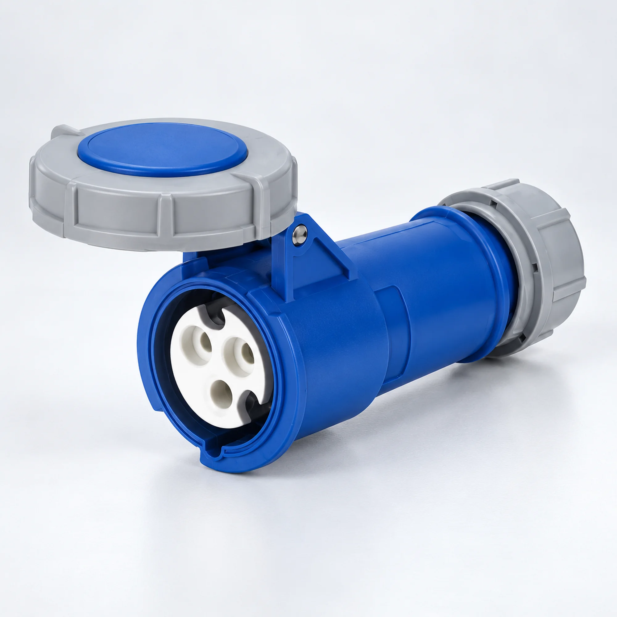
IP44 Industrial Cable Couplers
YOCL ELECTRIC IP44 industrial cable couplers for cable-end connections, with distinct housing designs and complete NM model selection tables.
- Rated currents: 16 A and 32 A.
- Contact arrangements: 2P+E, 3P+E and 3P+N+E.
- 4h, 6h and selected 9h earth-contact layouts, depending on model.
- Female cable connector with front cover.
- Select voltage, conductor capacity and dimensions by the full model code.
Overview
YOCL ELECTRIC IP44 industrial cable couplers are female cable connectors for industrial cable connections. This family brings together the actual 16 A and 32 A models listed below, with 2P+E, 3P+E and 3P+N+E contact arrangements. Each model has its own voltage, earth-contact clock position and housing design.
The connector end has female contacts and a protective front cover; the rear entry accepts the supply cable. H-design, K-design, white rear-body and special clock-position versions remain separate model groups so that the housing photograph and dimensional data can be matched to the correct connector.
Features
- IP44 protection rating for the listed models.
- Female contacts and a protective cover for the cable connector end.
- Rated current choices: 16 A and 32 A; the actual combinations are defined by the model tables.
- 2P+E, 3P+E and 3P+N+E versions are identified individually.
- Earth-contact layouts: 4h, 6h and selected 9h, according to the named model.
- Separate housing groups preserve each model’s conductor capacity and dimensional data.
Technical Specifications
| Parameter | Specification |
|---|---|
| Brand | YOCL ELECTRIC |
| Product type | Female cable connectors |
| Mounting | Cable-mounted |
| Protection rating | IP44 |
| Rated currents | 16 A and 32 A |
| Contact arrangements | 2P+E (3 contacts); 3P+E (4 contacts); 3P+N+E (5 contacts) |
| Earth-contact positions | 4h, 6h and selected 9h |
| Voltage configurations | See the individual model rows; paired five-contact ratings are retained as listed. |
| Conductor capacities | Model-specific values in mm²; see the selection tables. |
| Housing designs | See the separate model groups below. |
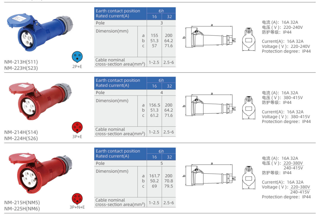
H housing design — 16 / 32 A
| Model | Printed reference | Current (A) | Contacts | Voltage (V) | Clock | Conductor capacity (mm²) | Body color |
|---|---|---|---|---|---|---|---|
| NM-213H-4 | 511 | 16 | 2P+E | 110–130 | 4h | 1–2.5 | Yellow |
| NM-223H-4 | 523 | 32 | 2P+E | 110–130 | 4h | 2.5–6 | Yellow |
| NM-213H | 511 | 16 | 2P+E | 220–240 | 6h | 1–2.5 | Blue |
| NM-223H | 523 | 32 | 2P+E | 220–240 | 6h | 2.5–6 | Blue |
| NM-214H | 514 | 16 | 3P+E | 380–415 | 6h | 1–2.5 | Red |
| NM-224H | 526 | 32 | 3P+E | 380–415 | 6h | 2.5–6 | Red |
| NM-215H | NM5 | 16 | 3P+N+E | 220–380 / 240–415 | 6h | 1–2.5 | Red |
| NM-225H | NM6 | 32 | 3P+N+E | 220–380 / 240–415 | 6h | 2.5–6 | Red |
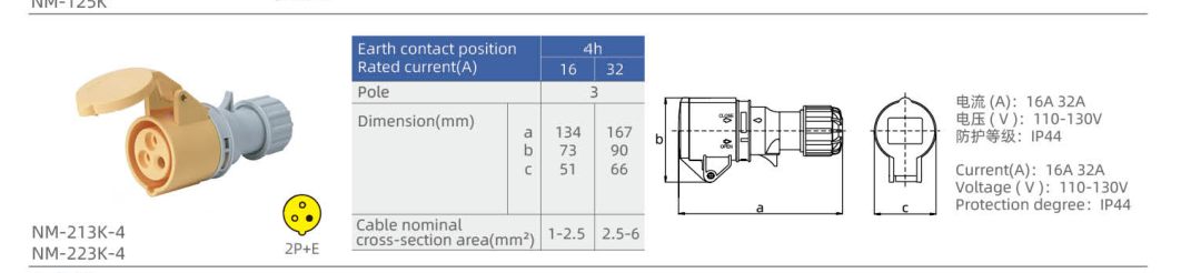
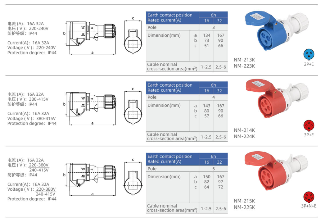
K housing design — 16 / 32 A
| Model | Current (A) | Contacts | Voltage (V) | Clock | Conductor capacity (mm²) | Body color |
|---|---|---|---|---|---|---|
| NM-213K-4 | 16 | 2P+E | 110–130 | 4h | 1–2.5 | Yellow |
| NM-223K-4 | 32 | 2P+E | 110–130 | 4h | 2.5–6 | Yellow |
| NM-213K | 16 | 2P+E | 220–240 | 6h | 1–2.5 | Blue |
| NM-223K | 32 | 2P+E | 220–240 | 6h | 2.5–6 | Blue |
| NM-214K | 16 | 3P+E | 380–415 | 6h | 1–2.5 | Red |
| NM-224K | 32 | 3P+E | 380–415 | 6h | 2.5–6 | Red |
| NM-215K | 16 | 3P+N+E | 220–380 / 240–415 | 6h | 1–2.5 | Red |
| NM-225K | 32 | 3P+N+E | 220–380 / 240–415 | 6h | 2.5–6 | Red |
White rear-body designs — 16 / 32 A
| Model | Current (A) | Contacts | Voltage (V) | Clock | Conductor capacity (mm²) | Body color |
|---|---|---|---|---|---|---|
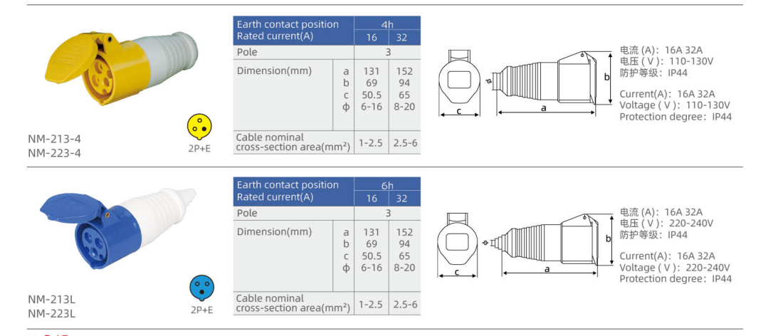
| NM-213-4 | 16 | 2P+E | 110–130 | 4h | 1–2.5 | Yellow |
| NM-223-4 | 32 | 2P+E | 110–130 | 4h | 2.5–6 | Yellow |
| NM-213L | 16 | 2P+E | 220–240 | 6h | 1–2.5 | Blue |
| NM-223L | 32 | 2P+E | 220–240 | 6h | 2.5–6 | Blue |
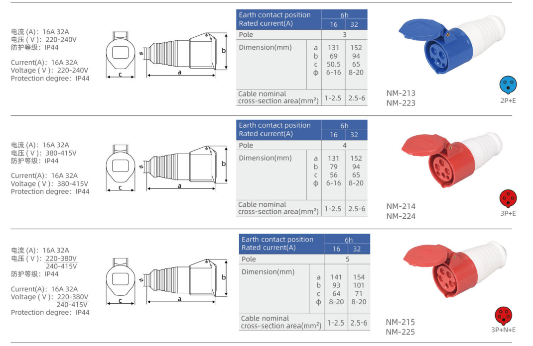
| NM-213 | 16 | 2P+E | 220–240 | 6h | 1–2.5 | Blue |
| NM-223 | 32 | 2P+E | 220–240 | 6h | 2.5–6 | Blue |
| NM-214 | 16 | 3P+E | 380–415 | 6h | 1–2.5 | Red |
| NM-224 | 32 | 3P+E | 380–415 | 6h | 2.5–6 | Red |
| NM-215 | 16 | 3P+N+E | 220–380 / 240–415 | 6h | 1–2.5 | Red |
| NM-225 | 32 | 3P+N+E | 220–380 / 240–415 | 6h | 2.5–6 | Red |
Special 9h contact layouts — 16 / 32 A
These 9h models use the particular voltage and contact layouts shown below. Their conductor capacities and dimensions are not extended from the ordinary models.
| Model | Current (A) | Contacts | Voltage (V) | Clock | Conductor capacity (mm²) | Body color |
|---|---|---|---|---|---|---|
| NM-213L-9 | 16 | 2P+E | 380–415 | 9h | — | Red |
| NM-223L-9 | 32 | 2P+E | 380–415 | 9h | — | Red |
| NM-214L-9 | 16 | 3P+E | 220–240 | 9h | — | Blue |
| NM-224L-9 | 32 | 3P+E | 220–240 | 9h | — | Blue |
Dimension
The symbols below reproduce each housing group’s dimensional table in millimetres. Letter meanings differ between drawings; a repeated symbol does not define one common dimension across all groups. Match the full model code and housing group before using a drawing.
H housing design — 16 / 32 A
| Model | Drawing/table dimensions (mm) |
|---|---|
| NM-213H-4 | a = 155; b = 51.3; c = 57 |
| NM-223H-4 | a = 200; b = 64.2; c = 71.6 |
| NM-213H | a = 155; b = 51.3; c = 57 |
| NM-223H | a = 200; b = 64.2; c = 71.6 |
| NM-214H | a = 156.5; b = 51.3; c = 61.2 |
| NM-224H | a = 200; b = 64.2; c = 71.6 |
| NM-215H | a = 161.7; b = 50.2; c = 69 |
| NM-225H | a = 200; b = 70.8; c = 79.5 |
K housing design — 16 / 32 A
| Model | Drawing/table dimensions (mm) |
|---|---|
| NM-213K-4 | a = 134; b = 73; c = 51 |
| NM-223K-4 | a = 167; b = 90; c = 66 |
| NM-213K | a = 134; b = 73; c = 51 |
| NM-223K | a = 167; b = 90; c = 66 |
| NM-214K | a = 143; b = 80; c = 57 |
| NM-224K | a = 167; b = 90; c = 66 |
| NM-215K | a = 150; b = 82; c = 64 |
| NM-225K | a = 167; b = 97; c = 72 |
White rear-body designs — 16 / 32 A
| Model | Drawing/table dimensions (mm) |
|---|---|
| NM-213-4 | a = 131; b = 69; c = 50.5; φ = 6–16 |
| NM-223-4 | a = 152; b = 94; c = 65; φ = 8–20 |
| NM-213L | a = 131; b = 69; c = 50.5; φ = 6–16 |
| NM-223L | a = 152; b = 94; c = 65; φ = 8–20 |
| NM-213 | a = 131; b = 69; c = 50.5; φ = 6–16 |
| NM-223 | a = 152; b = 94; c = 65; φ = 8–20 |
| NM-214 | a = 131; b = 79; c = 56; φ = 6–16 |
| NM-224 | a = 152; b = 94; c = 65; φ = 8–20 |
| NM-215 | a = 141; b = 93; c = 64; φ = 8–20 |
| NM-225 | a = 154; b = 101; c = 71; φ = 8–20 |
Selection Guide
Choose a female cable coupler when the mating connection is made at the end of a cable. A wall-mounted socket or an appliance inlet belongs to a different mounting and contact family.
Select the current rating, contact arrangement, rated voltage, earth-contact clock position and IP rating together from one actual model row. Body color alone is insufficient: the special clock-position groups include different voltage/contact combinations from the ordinary groups.
Keep the complete suffix when selecting the housing version. Models that share an electrical rating may have different lengths, cable-entry dimensions or body shapes. Conductor capacity is a cross-sectional range in mm² and must not be confused with a cable-entry dimension in mm.
For five-contact models, the table preserves the paired 220–380 / 240–415 V notation. It does not create an additional arbitrary voltage combination. A dash in the capacity column means that the particular row supplies no confirmed value.
Ordering Information
When enquiring about YOCL ELECTRIC IP44 industrial cable couplers, provide the full model code, quantity, current rating, contact arrangement, rated voltage, clock position and the required housing design. Include the conductor cross-section and cable outside diameter so that the cable entry and terminal range can be checked for that specific model.
Printed secondary references identify the catalogue entries where shown; they do not create extra model options or replace the full NM model code.