
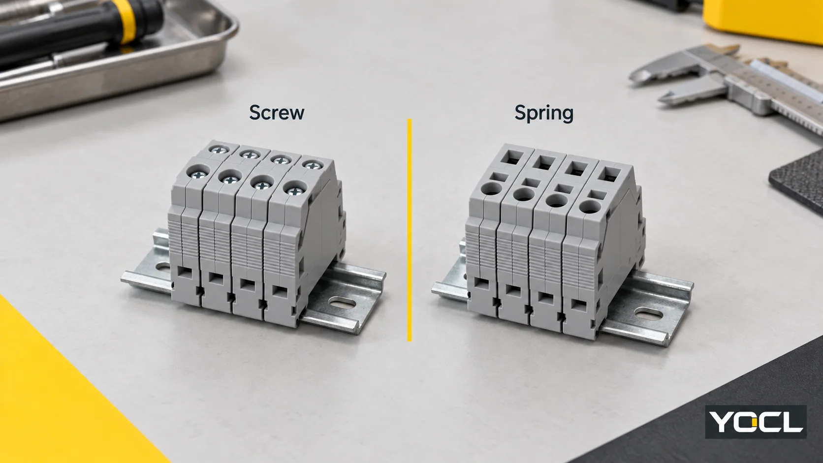
Belgelenmiş bir sıkma işlemi montaj ve servis uygulamanıza uyduğunda vida klemensleri seçin. Tel hazırlığını ve çalışmasını onayladıktan sonra, iletken-kelepçe tork ayarı adımını kaldırmak iş akışınıza uyduğunda yaylı klemensleri seçin. Doğrudan itme, bir yay tasarımıdır. Bağlantı etiketlerinden hiçbiri bir denetim aralığı belirlemez.
Bu karşılaştırma, bakır iletkenler için modüler DIN ray klemenslerini ilgilendirmektedir. Aynı devre fonksiyonuna, uygun elektriksel değerlere ve servis koşullarına sahip adayları karşılaştırın. Klemens fonksiyonları ve montaj biçimlerinin daha geniş haritası için, terminal bloğu kılavuzu.
Kablolama ödünleşimleri: işin nereye gittiği
Faydalı karşılaştırma, tel hazırlığı ve erişim dahil olmak üzere eksiksiz sonlandırma ve yeniden işleme işlemidir.
| Karşılaştırma noktası | Vidalı terminal | Yaylı terminal |
|---|---|---|
| İletken-kelepçe işlemi | Bağlantı bir vida ile sağlanır; belirlenen sıkma değerini ve alet gereksinimlerini alın | Giriş, tasarıma bağlı olarak kelepçe açıklığı gerektirir veya doğrudan itme imkanı tanır |
| Tel uygunluğu | İletken tipini, boyutunu ve izin verilen hazırlığını onaylayın | Aynı alanları onaylayın; yay etiketi bunları belirlemez |
| Yeniden işleme sırasında erişim | Sıkma vidasına ve iletken girişine erişime izin verin | Açma/serbest bırakma özelliğine ve iletken girişine erişime izin verin |
| Karşılaştırma iş akışı | Hazırlık, yerleştirme, sıkma, belgelenmiş kontroller ve çıkarma | Hazırlık, açma/yerleştirme, belgelenmiş kontroller ve serbest bırakma |
Vidalı bağlantılar, ara bir kelepçeleme parçası aracılığıyla basınç iletebilir. Her vida ucunun doğrudan tele temas ettiğini varsaymayın. Uluslararası Elektroteknik Komisyonu (IEC), terminolojisinde doğrudan ve dolaylı vida etkisini ayırt eder. IEC 60999-1 genel önizleme, Bölüm 3.
Adil bir montaj karşılaştırması için aynı iletkeni kullanın ve her uygun model için gerçek atölye hazırlık ve kabul sürecini tekrarlayın. Hızlı bir yerleştirme gösterisi, yüksük hazırlığını, sıkma kontrolünü veya daha sonra iletkenin çıkarılmasını ölçmez. Eşleşen ölçümler olmadan, kablolama hızı hakkındaki yüzdesel iddia, karara çok az şey katar.
Yaylı kelepçe ve itmeli tip farklı şeyleri tanımlar
Yaylı kelepçe, kelepçeleme mekanizmasını tanımlar; itmeli tip, bir giriş eylemini tanımlar. Yaylı tasarımlar bir aletle açılabilir, bir aktüatör aracılığıyla çalıştırılabilir veya doğrudan takılarak kullanılabilir. IEC 60352-7 bu farklı düzenekleri göstermektedir. IEC 60352-7:2026 genel önizleme, Şekil 1.
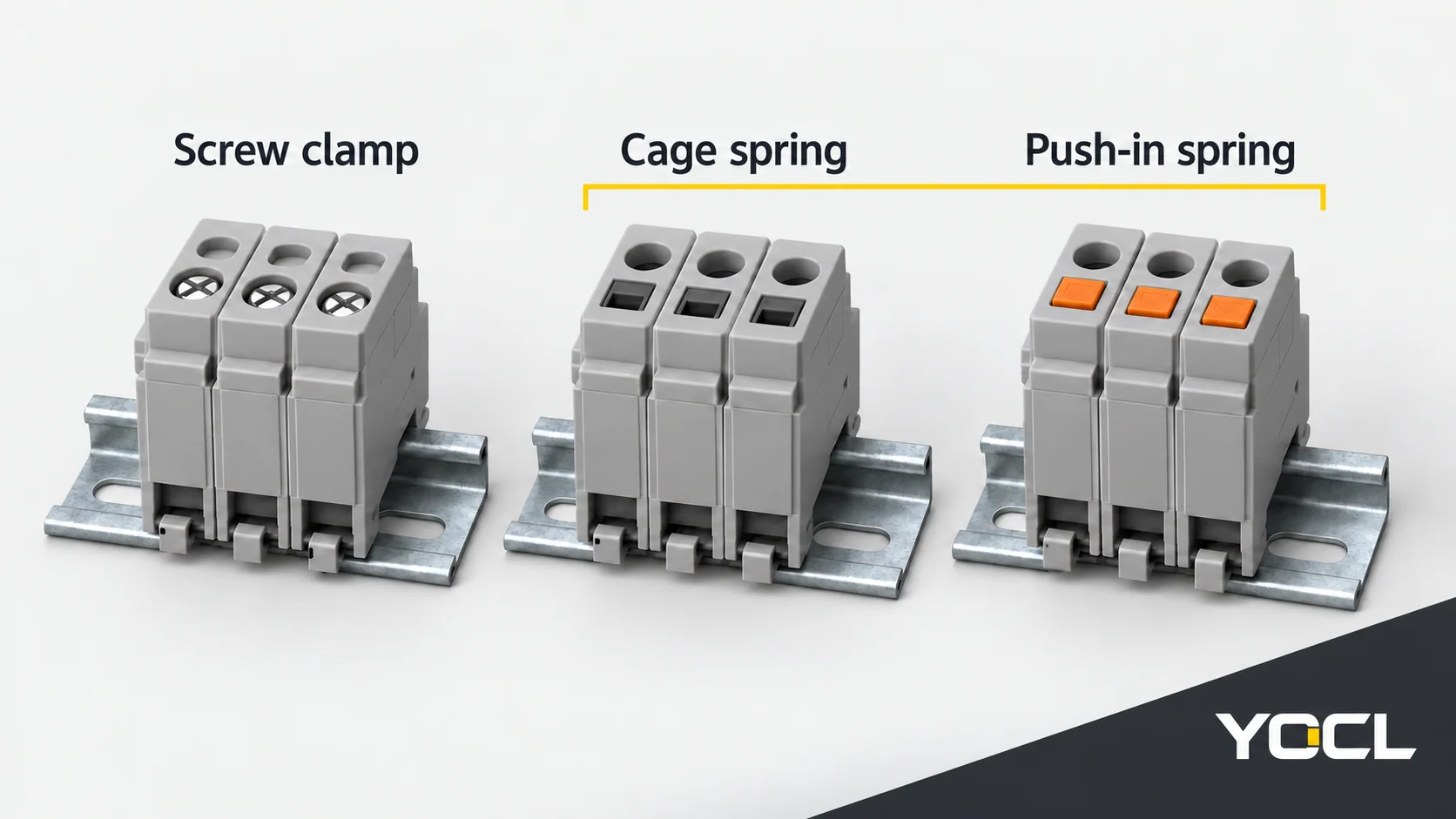
Doğrudan takma, aletsiz sökme sağlamaz. Çevredeki kablolama ve takılı aksesuarlarla birlikte sökme erişimini doğrulayın.
İletken hazırlığı seçimi değiştirebilir
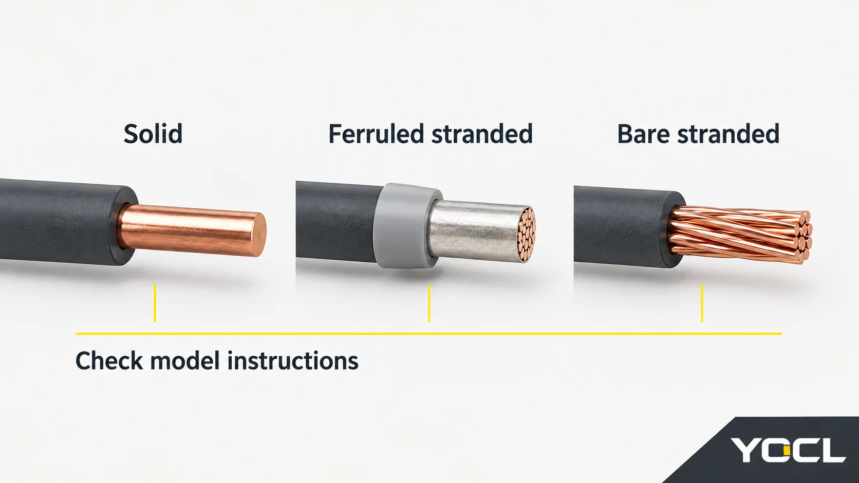
İletken kabulü, kelepçe tipinden ayrı bir özelliktir. IEC 60947-7-1 terminal bloklarını kabul edilen iletken formlarına ve hazırlık kapasitesine göre sınıflandırır ve anma kesitini bir bağlantı kapasitesi aralığından ayırır. IEC 60947-7-1:2025 genel önizleme, Bölümler 3–4.
Katı uç, çıplak telli uç ve yüksüklü uç farklı sonlandırma koşulları sunar. İletken tipiniz, boyutunuz, hazırlığınız ve iletken sayınız için ilgili bloğun bilgilerini kontrol edin. Bir yüksük, her terminali o kablo için otomatik olarak uygun hale getirmez. The tel-yüksük kılavuzu explains the prepared-end compatibility question in more detail.
YOCL lists UK screw, SJ cage-spring and PT push-in ranges. Their public model information demonstrates why a similar size designation is insufficient for substitution.
| Example and source | Publicly declared field | What it leaves to confirm |
|---|---|---|
| UK-2.5B in the UK screw range | The row identifies an M3 screw but does not give a conductor range | Accepted conductor/preparation range and tightening torque; M3 is a screw size, not a torque |
| SJ-2.5 in the cage-spring range | Rigid conductors: 0.2–4 mm²; flexible conductors: 0.2–2.5 mm² | Preparation-specific acceptance and opening/release instructions |
| PT2.5 in the PT push-in range | Rated cross-section: 2.5 mm²; the series describes direct insertion of suitable solid or ferruled conductors | Complete accepted ranges for the selected prepared end and release method |
These are first-party catalogue fields, not a matched performance test. The flexible-conductor range given for SJ-2.5 cannot be transferred to PT2.5. Request the missing model information before treating either as a replacement for an existing terminal.
Maintenance: separate tightening from inspection
For a screw terminal, the installation process needs the prescribed tightening instructions. Its maintenance policy must separately state whether and when retightening is required. Obtain that policy for the exact terminal and equipment; do not invent an annual interval from the connection name.
A spring conductor clamp removes the user-set tightening operation at that contact. It does not remove the need to investigate damaged parts, deteriorating wiring or an unsuitable connection. If a supplier calls a terminal “maintenance-free,” ask which task that statement excludes and which inspections remain in the equipment maintenance plan.
As an example of wider maintenance guidance, Great Britain’s Health and Safety Executive calls for maintenance to prevent danger and competent inspection/testing of fixed installations. Its general equipment guidance identifies damaged connectors, insecure cables and burn marks as reasons for action. It supplies no DIN-terminal retightening interval. HSE, Introduction to electrical safety.
For either mechanism, arrange any connection work under the equipment’s isolation and service instructions. A suspected damaged contact needs competent assessment; changing the clamping technology does not establish that the underlying problem has been resolved.
Which tradeoff fits your panel?
| Your situation | Candidate decision | Condition that makes the decision defensible |
|---|---|---|
| Established screw design, controlled tightening tools and accessible terminals | Retain or select screw terminals | The exact conductor and service instructions fit; the present process has a clear acceptance method |
| Repeated assembly using one confirmed prepared end | Consider a suitable direct push-in spring terminal | Evaluate the whole preparation/insertion/release process, not insertion alone |
| Field wiring brings different conductor forms | Either a compatible screw or an opened-spring design may fit | Verify every expected wire form; do not infer direct-insertion eligibility from the spring label |
| Different circuits have different service needs | Both mechanisms may belong in the panel | Qualify each connection and keep its instructions identifiable |
| The choice is being justified by vibration, heating or reliability alone | Neither label decides | Obtain application-specific declarations or matched evidence for the exact candidates |
For a change of series, also verify the footprint, rail fit, end plates, bridges and markers. Shared DIN mounting does not establish accessory interchangeability. Keep screw or release access usable during the intended service task.
Kullanın YOCL terminal-block range to identify candidates. Provide the conductor types and prepared ends, circuit function, required ratings and access constraints, then request the matching connection and maintenance documents. That turns a mechanism preference into a reviewable terminal choice.
Referanslar
- IEC, IEC 60999-1:1999 — public preview, Section 3, screw and screwless clamping terminology.
- IEC, IEC 60352-7:2026 — public preview, Section 3 and Figure 1, spring-clamp terminology and operation.
- IEC, IEC 60947-7-1:2025 — public preview, Sections 3–4, terminal-block definitions and classification. Only cited public preview sections were consulted; these references do not establish YOCL certification.
- YOCL ELECTRIC, UK Serisi Vidalı DIN Ray Klemensleri, UK-2.5B catalogue row.
- YOCL ELECTRIC, SJ Kafes Yaylı DIN Ray Klemensler, SJ-2.5 catalogue row.
- YOCL ELECTRIC, PT Serisi Yaylı Sıkmalı DIN Ray Klemensler, PT2.5 row and series operation description. First-party pages checked 11 October 2026.
- Health and Safety Executive, Great Britain, Introduction to electrical safety, Maintenance and Fixed installations.