
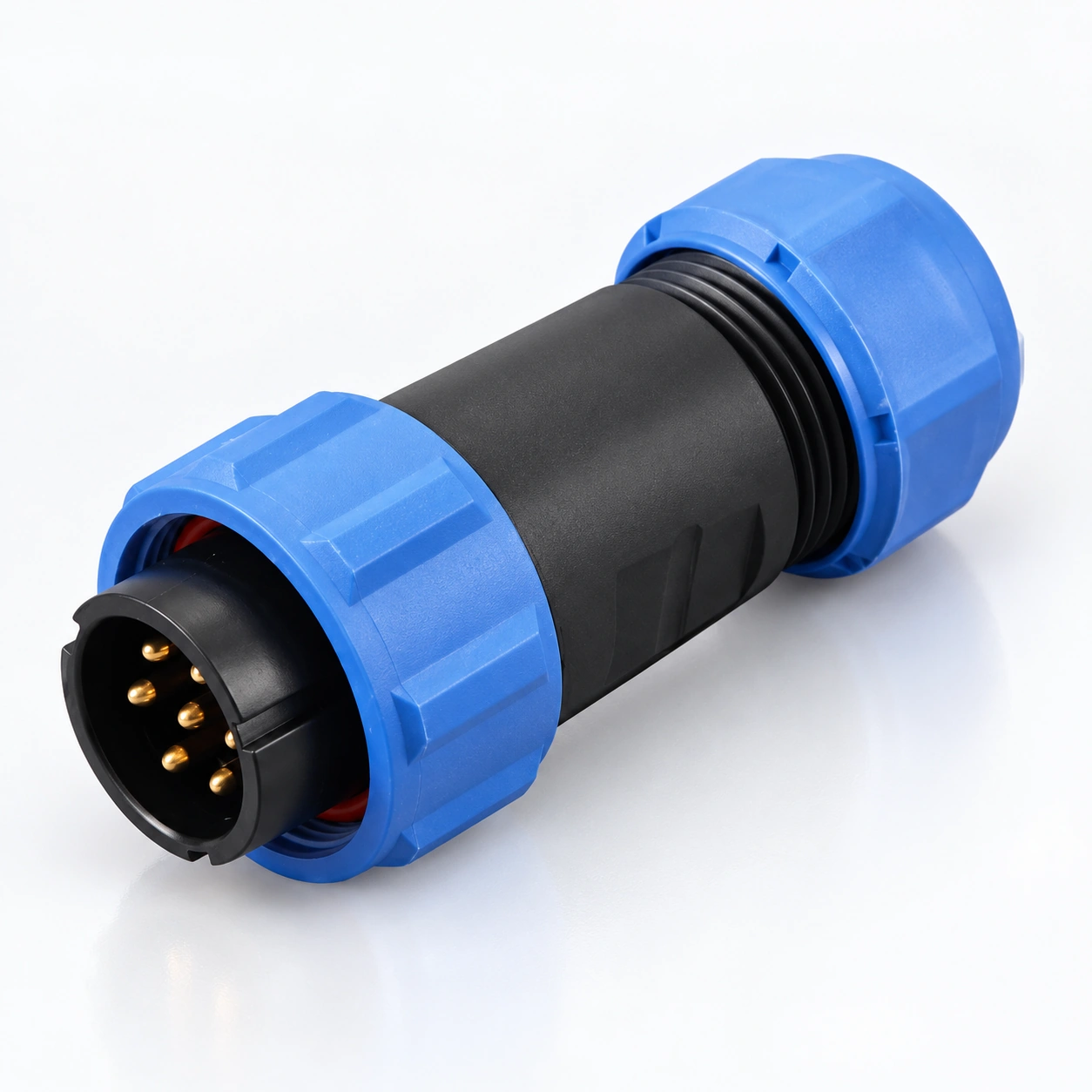
SP29 Su Geçirmez Yuvarlak Konnektörler
YOCL ELEKTRİKLİ SP29 Su Geçirmez Yuvarlak Konnektörler, dişli kilitleme ve seçilebilir kontak konfigürasyonları ile kablo ve ekipman arayüzleri sağlar.
- 2 / 3 / 4 / 5 / 7 / 9 / 12 kontaklar; pin ve soket seçenekleri.
- IP68 katalog değeri ve −40 °C ila +85 °C sıcaklık aralığı.
- Altın kaplama bakır kontaklar, PC / PA66 gövdeler ve PPS yalıtkanlar.
- Düz ve açılı kablo fişleri, hat içi soketler ve panel soket formatları.
- Düz kablo fişi ve hat içi kablo soketi: 13–16 mm kablo dış çapı.
- Lehim, vidalı terminal ve sıkma seçenekleri yapılandırmaya bağlıdır.
Genel Bakış
YOCL ELEKTRİK SP29 Su Geçirmez Yuvarlak Konnektörler, ayrılabilir kablo-kablo ve kablo-panel elektrik bağlantıları sağlar 2, 3, 4, 5, 7, 9 veya 12 kontaklar. Dişli bir kuplaj, eşleşen gövdeleri sabitlerken, pin ve soket kontak seçenekleri gerekli elektrik düzeninin seçilmesine olanak tanır.
Seri, düz ve açılı kablo fişleri, hat içi kablo soketleri, arka somunlu panel soketleri ve flanş montajlı soketler içerir. Düz kablo fişi ve hat içi kablo soketi şunlar için listelenmiştir: 13–16 mm kablo dış çapları. Katalog listeler IP68 koruma, kontak konfigürasyonu tarafından seçilen elektriksel ve kablo sonlandırma özellikleriyle.
Özellikler
- Diş kilitleme: Bir vida kuplajı, eşleşen konektör gövdelerini birleştirir.
- Yedi kontak sayısı seçeneği: 2, 3, 4, 5, 7, 9 veya 12 kontak seçin.
- Kablo ve panel gövde stilleri: Düz fişler, hat içi bağlantılar, açılı fişler ve ekipman soketleri listelenmiştir.
- Pin ve soket kontakları: P ve S tanımlamaları elektriksel kontak tipini ifade eder.
- Altın kaplama bakır kontaklar: Katalogda altın kaplamalı bakır kontaklar belirtilmiştir.
- Seçilebilir sonlandırma: Lehim, vidalı terminal ve sıkma versiyonları listelenmiştir, yapılandırmaya özel limitler mevcuttur.
Teknik Özellikler
| Parametre | Teknik Özellikler |
|---|---|
| Marka | YOCL ELEKTRİK |
| Seri | SP29 |
| Konnektör tipi | Su geçirmez dairesel konnektör |
| Kontak sayısı | 2 / 3 / 4 / 5 / 7 / 9 / 12 |
| Kavrama | Diş kilitleme |
| Kontak tipleri | P: pin; S: soket |
| Gövde malzemeleri | Termoplastik PC / PA66 |
| Gövde malzemesi yangın derecesi | V-0 |
| Yalıtkan | Termoplastik PPS |
| Kontaklar | Altın kaplama bakır |
| Koruma sınıfı | IP68, katalog derecelendirmesi |
| Katalog eşleşme döngüsü rakamı | 500 |
| Sıcaklık aralığı | −40 °C ila +85 °C |
| Yalıtım direnci | 2000 MΩ |
Elektriksel Kontak Verileri
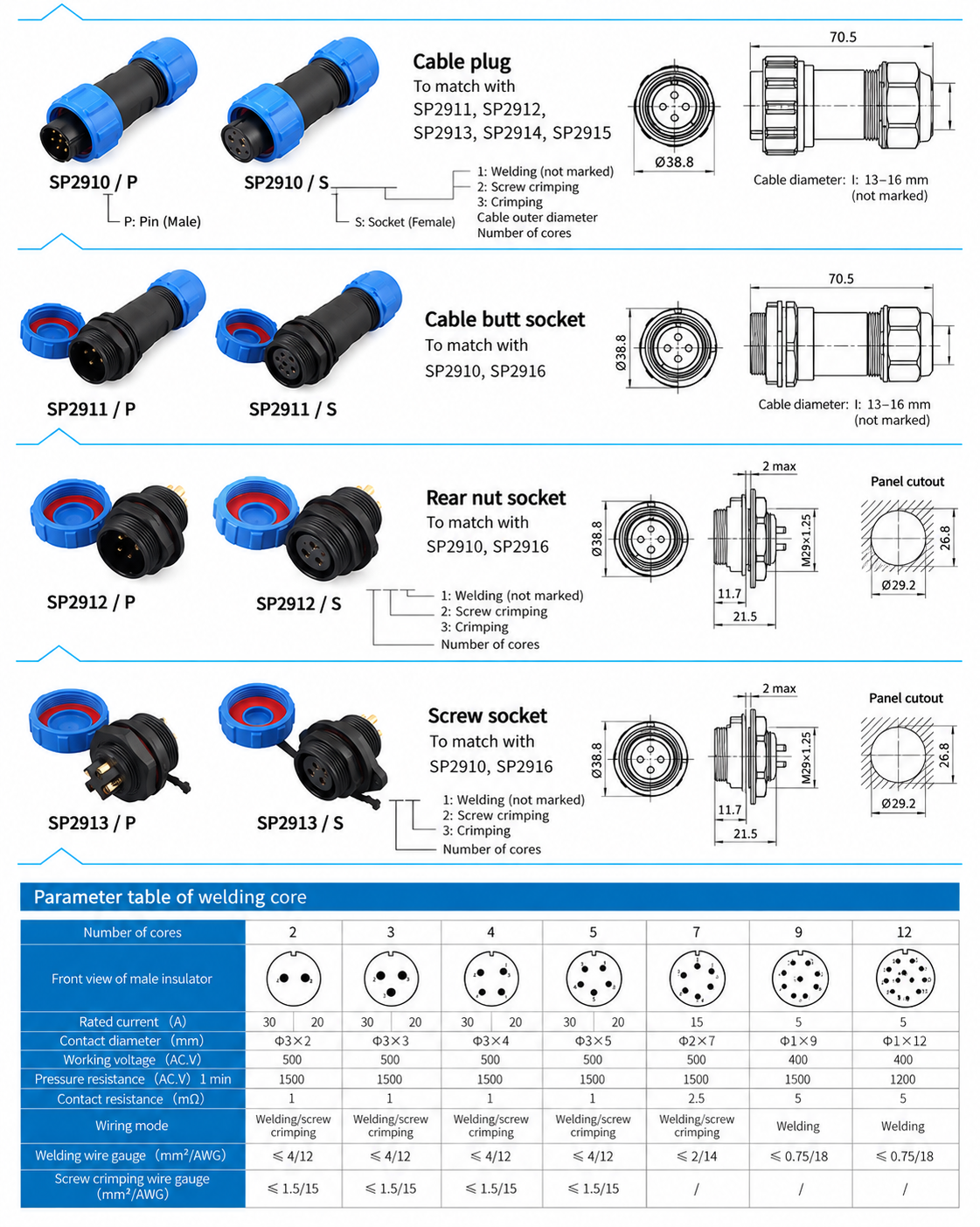
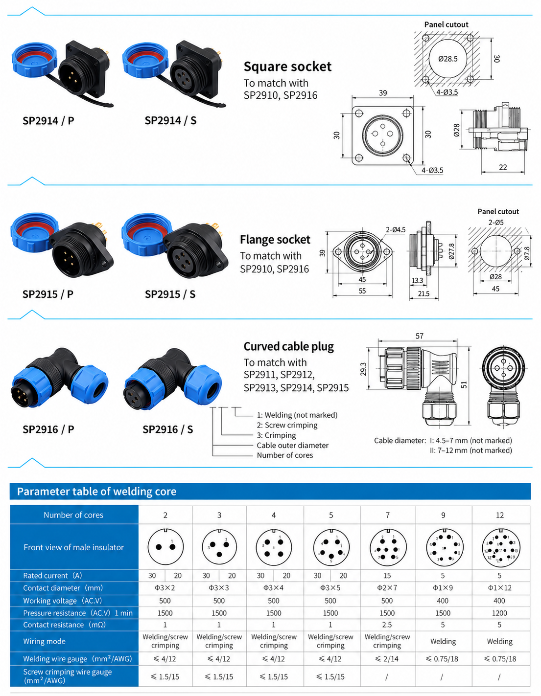
Aşağıdaki değerler katalogun lehim kontak parametreleri tablosundan alınmıştır. Bunlar, kıvırma kontakları için ayrı bir spesifikasyon değildir.
| Kontaklar | Anma akımı | Kontak çapı × adet | Çalışma gerilimi, AC | Dayanım gerilimi, AC, 1 dakika | Kontak direnci |
|---|---|---|---|---|---|
| 2 | — | Ø3 mm × 2 | 500 V | 1500 V | 1 mΩ |
| 3 | — | Ø3 mm × 3 | 500 V | 1500 V | 1 mΩ |
| 4 | — | Ø3 mm × 4 | 500 V | 1500 V | 1 mΩ |
| 5 | — | Ø3 mm × 5 | 500 V | 1500 V | 1 mΩ |
| 7 | 15 A | Ø2 mm × 7 | 500 V | 1500 V | 2.5 mΩ |
| 9 | 5 A | Ø1 mm × 9 | 400 V | 1500 V | 5 mΩ |
| 12 | 5 A | Ø1 mm × 12 | 400 V | 1200 V | 5 mΩ |
İki ila beş kontaklı konfigürasyonlar için, sipariş verirken seçilen sonlandırma ve parça numarası için akım değerini alın. Çalışma gerilimi ve bir dakikalık dayanım değeri farklı parametreleri açıklar.
Sonlandırmaya Göre İletken Limitleri
| Kontaklar | Lehimli iletken limiti | Katalog AWG girişi | Vidalı terminal iletken limiti | Katalog AWG girişi |
|---|---|---|---|---|
| 2 / 3 / 4 / 5 | ≤4 mm² | 12 AWG | ≤1.5 mm² | 15 AWG |
| 7 | ≤2 mm² | 14 AWG | — | — |
| 9 / 12 | ≤0.75 mm² | 18 AWG | — | — |
Metrik limitler ve AWG girişleri katalog çiftleri olarak çoğaltılmıştır. Bir tire işareti, bu tablodaki sonlandırma için iletken limiti sağlanmadığı anlamına gelir. Tel boyutunu kontak yuvası ve sonlandırma ile birlikte seçin. Sıkmaya özel iletken limitleri burada belirtilmemiştir.
Kablo Kılıfı Seçimi
| Uygulanabilir gövde stilleri | Listelenen kablo dış çapı |
|---|---|
| SP2910 straight cable plugs and SP2911 inline cable sockets | 13–16 mm |
The angled SP2916 cable diameter is not specified here. Include the actual cable diameter when requesting that body style.
Boyut
Konnektör Gövde Boyutları
| Temel model | Listelenen gövde boyutları |
|---|---|
| SP2910 straight cable plug | 70.5 mm overall length; 38.8 mm front width |
| SP2911 inline cable socket | 70.5 mm overall length; Ø38.8 mm front diameter |
| SP2912 / SP2913 panel sockets | 21.5 mm overall length; M29 × 1.25 mounting thread; panel thickness 2 mm max. |
| SP2914 square-flange socket | 39 × 39 mm flange; 22 mm overall axial length; 30 mm mounting-hole pitch; Ø3.5 mm body mounting holes |
| SP2915 two-hole flange socket | 55 mm body width × 39 mm height; 45 mm hole pitch; two Ø4.5 mm body mounting holes; 21.5 mm overall length |
Panel Opening Dimensions
| Panel socket | Listed panel opening |
|---|---|
| SP2912 / SP2913 | Ø29.2 mm opening with 26.8 mm flat-to-flat height |
| SP2914 | 28.5 mm central opening; Ø3.5 mm mounting holes on the shown 30 mm pitch |
| SP2915 | Ø28 mm central opening; two Ø5 mm mounting holes on 45 mm centres |
Connector-body holes and panel mounting holes have separate dimensions. Use the selected socket’s complete installation drawing to check the opening shape and hole positions.
Konnektör Formatları ve Eşleşen Aileler
| Base body model | Format | Listed mating family |
|---|---|---|
| SP2910 | Straight cable plug | SP2911 / SP2912 / SP2913 / SP2914 / SP2915 |
| SP2911 | Inline cable socket | SP2910 / SP2916 |
| SP2912 | Rear-nut panel socket | SP2910 / SP2916 |
| SP2913 | Panel socket, style 13 | SP2910 / SP2916 |
| SP2914 | Square-flange panel socket | SP2910 / SP2916 |
| SP2915 | Two-hole flange panel socket | SP2910 / SP2916 |
| SP2916 | Angled cable plug | SP2911 / SP2912 / SP2913 / SP2914 / SP2915 |
Each body family is shown with /P pin ve /S socket contact options. Match the contact count and opposite electrical contact types as well as the body families when specifying a mating pair.
Sipariş Bilgileri
Use the base body model and contact designation, such as SP2910/P for a straight cable plug with pin contacts or SP2914/S for a square-flange body with socket contacts. These are catalogue base designations; contact count, cable seal range and termination must also be specified.
The catalogue’s termination legend uses 1 for soldering (unmarked), 2 for screw termination ve 3 for crimping. The presence of a termination in the legend does not establish that every body and contact-count combination is available in that form. Obtain the complete part number for the requested configuration.
Seçim Kılavuzu
- Select the body style and mating body family.
- Specify pin or socket contacts and the required contact count on both sides.
- Select the termination and conductor size using the applicable limits.
- Match the cable seal to the cable jacket diameter; for panel versions, use the format-specific opening dimensions.
- Specify the required current, AC working voltage, quantity and mating-part requirements. Obtain model-specific data for a crimp version or a two- to five-contact current rating.
Uygulamalar
- Detachable equipment wiring.
- Inline cable connections.
- Panel-mounted electrical interfaces.
- Multi-contact power and signal connections.