
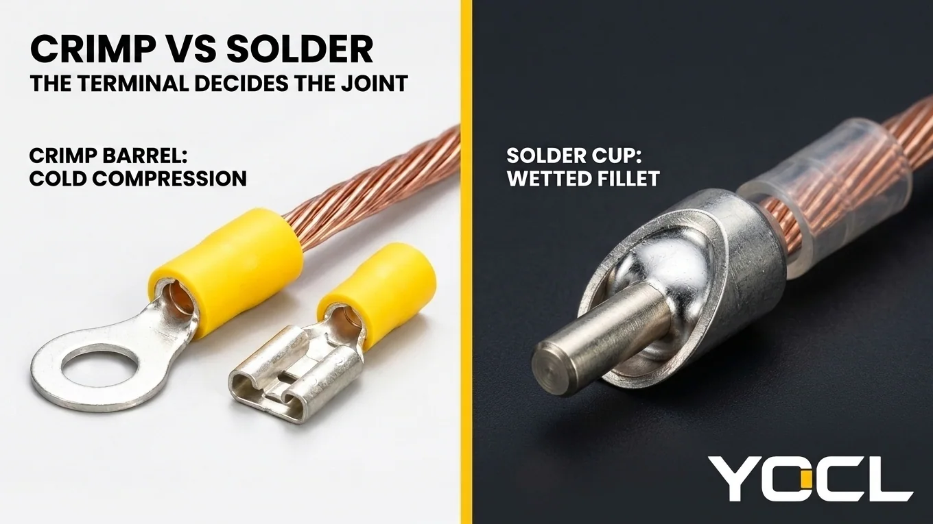
La elección entre terminales crimpados vs. soldadura es una regla de compatibilidad del diseño del terminal, no una preferencia de banco. Un terminal crimpado es un sistema cualificado de compresión en frío donde el cuerpo, el rango de cable y la matriz deforman los hilos del conductor en una masa hermética a los gases, primero mecánica y eléctrica como resultado, mientras que la sustitución de metal de aporte de soldadura blanda convierte un cuerpo crimpado en una unión no probada.
La regla de decisión que rige todo el artículo es directa: fijar el terminal por el método para el que el terminal fue diseñado y cualificado. Para los terminales crimpados utilizados en cableado de campo, paneles, vehículos y maquinaria, incluida toda la línea de terminales aislados en el sitio de YOCL, como los terminales de desconexión rápida hembra preaislados FDD/FDVD de YOCL y los terminales de anilla preaislados RV de YOCL, cuyas páginas de producto especifican cuerpos crimpados y construcciones crimpadas y no publican variante de soldadura, ese método es el crimpado. El territorio legítimo de la soldadura es real y debe nombrarse de manera justa: ensamblaje de circuitos impresos, electrónica estática y terminales diseñados para soldadura, como casquillos de soldadura y formas de ojo de soldadura. Tratar la elección como “crimpado bueno, soldadura mala” omite la regla; el diseño del terminal decide, como se refleja en las normas marinas (ABYC E-11), las normas de mano de obra aeroespacial (NASA-STD-8739.4A), las normas de aceptación de arneses (IPC/WHMA-A-620) y las especificaciones de los terminales.
Para mantener separadas las preguntas adyacentes, note dónde vive cada tema vecino. A qué pertenece un terminal de crimpado qué es un terminal de crimpado. Los extremos de cable estañados dentro de bloques de terminales de tornillo pertenecen a cable trenzado estañado en bloques de terminales—este artículo trata sobre cómo se conecta el terminal al cable, no sobre lo que hace una abrazadera a un extremo estañado.
| Escenario | Mecanismo de unión | Estado del cable fuera del barril | Calificación | Decisión de campo |
|---|---|---|---|---|
| Barril de crimpado + matriz emparejada | La compresión en frío forma una masa estanca al gas | Flexible hasta la entrada del barril | Sistema de barril-cable-herramienta calificado | Uso para terminales especificados para crimpado |
| Copa de soldadura o almohadilla de PCB | El metal de relleno humedece las superficies sin fusión | Soportado por PCB, copa o manguito | Calificado bajo IPC/WHMA-A-620 | Usar donde esté diseñado para soldadura |
| Barril de crimpado + soldadura solamente | El relleno blando es el único vínculo en el barril sin crimpado | La capilaridad crea una varilla rígida | Prohibido como único vínculo (ABYC E-11) | Rechazar; recortar y volver a crimpado |
| Cable pre estañado, luego crimpado | El troquel comprime el barril sobre el tapón de soldadura rígido | La soldadura blanda se filtra bajo presión | Prohibido por las normas aeroespaciales (NASA-STD-8739.4A) | Nunca estañe los hilos antes de crimparlos |
Regla de selección: Elija crimpado por compresión en frío con un troquel emparejado siempre que termine un cable trenzado en un barril especificado para crimpado (como terminales de anillo, espade, desconexión rápida o terminales tubulares); cambie a soldadura solo cuando termine conductores en copas de soldadura dedicadas, postes de ojo de soldadura o placas de circuito impreso rígidas equipadas con alivio de tensión mecánica.
Lo que cada proceso realmente produce: La unión por compresión en frío vs la unión llena
El crimpado de cable por compresión en frío y el humedecimiento por soldadura capilar crean interfaces metalúrgicas fundamentalmente diferentes dentro de un barril de terminal. Un troquel de crimpado emparejado deforma plásticamente el metal del barril y los hilos de cobre en un bloqueo mecánico unificado y estanco al gas sin metal de relleno, mientras que la soldadura une superficies con un relleno de aleación de estaño fundido que permanece más blando que el cobre bajo carga mecánica.
En un engaste de compresión en frío, el cable trenzado pelado entra en un barril cuya espesor de pared, temple y estrías coinciden con un rango de cable definido. A medida que los troqueles coincidentes se cierran, la compresión supera la resistencia al rendimiento tanto del barril como de los hilos. Los hilos redondos se aplanan en polígonos entre sí y contra la pared del barril, eliminando películas superficiales, extruyendo aire y bloqueando superficies metálicas bajo tensión de sujeción elástica. El cobre se apoya directamente contra el cobre o el latón estañado, manteniendo la oxidación fuera mientras deja que los hilos fuera del barril se deslicen libremente a medida que el cable se flexiona. Para la elección de manguitos y sistemas de aislamiento a través de PVC, nylon y barriles desnudos, consulte PVC frente a terminales de crimpado de nailon o no aislados.
Una unión soldada hace una unión llena en lugar de una comprimida o soldada. Como NASA-STD-8739.4A lo define, la soldadura une superficies metálicas limpias mediante el uso de soldadura sin fusión directa de los metales base. El fundente limpia los óxidos mientras el calor lleva los hilos y el barril a la temperatura de humectación, atrayendo soldadura fundida entre ellos por acción capilar. Una vez solidificada, la soldadura forma una matriz de relleno conductora que conduce bien desde el primer día. Mecánicamente, sin embargo, los hilos de cobre no están bloqueados plásticamente a la pared del barril; se asientan en una matriz de relleno fundido más blanda que el cobre en resistencia al corte y al fluencia. Dentro de un vaso de soldadura o pad de PCB, el cuerpo del terminal o la placa soporta la carga mecánica; dentro de un barril de engaste flexible, se le pide a ese relleno blando que soporte una tensión que nadie probó que pudiera resistir.
Por qué fallan las uniones de soldadura donde sobreviven los engastes: Capilaridad, fluencia y el punto duro
Los terminales de cable soldados instalados en paneles vibrantes, vehículos, barcos o maquinaria industrial fallan mecánicamente antes de fallar eléctricamente. La capilaridad de la soldadura endurece los hilos flexibles en una varilla rígida fuera del barril, concentrando la fatiga por flexión en la abrupta transición dura-blanda, mientras que la fluencia de la soldadura y el ablandamiento térmico debilitan el agarre mecánico dentro de la unión.
El mecanismo principal es capilaridad. Se utiliza cable trenzado en arneses porque los finos hilos de cobre se flexionan fácilmente a medida que los hilos individuales se deslizan entre sí. Cuando la soldadura fundida toca el cable trenzado calentado, la acción capilar atrae la soldadura líquida entre los hilos, más allá del barril, convirtiendo una longitud de conductor flexible en una varilla rígida.
Esa sección capilar crea el punto duro—una abrupta transición dura–blanda justo fuera de la unión. Como se documenta en NASA-STD-8739.4A, un conductor trenzado soldado es rígido hasta el punto donde se detiene la capilaridad y flexible más allá de él. La flexión y la vibración se concentran entonces en la transición dura–blanda justo fuera de la unión, y los hilos se fatigan y rompen allí—este es el fallo clásico en el campo.
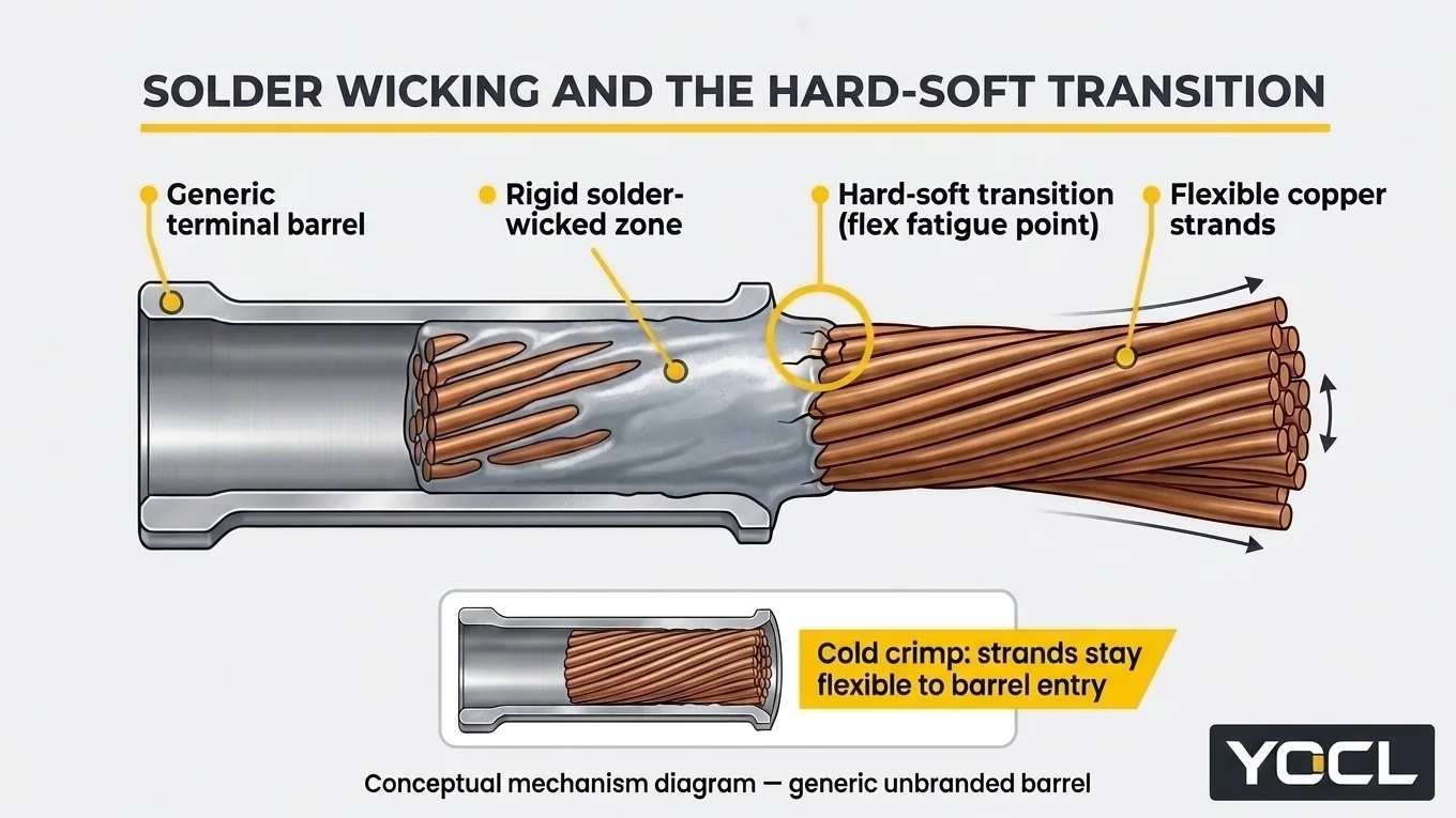
Dentro del barril, la soldadura también está sujeta a fluencia y ablandamiento. La soldadura se deforma lentamente bajo carga sostenida y ciclos térmicos, y pierde resistencia muy por debajo del rango de trabajo del cobre si un circuito se sobrecalienta; una unión que depende únicamente de la soldadura para el agarre mecánico está dependiendo del elemento más débil y blando en el ensamblaje.
A correct crimp behaves differently. Compression cold-flows barrel and strands together, the conductor stays flexible right up to the barrel, and the joint’s pull strength is a tested property of the terminal system—those numbers live in hammer crimp vs hydraulic crimp for battery lugs and in makers’ data. None of this applies to a joint designed for solder: a solder-cup terminal or a PCB joint is engineered around solder’s properties, with the board or the terminal body providing the mechanical support the solder lacks.
The Three Wrong Orders: What Happens When Methods Are Substituted or Mixed
Field failures in wire-terminal assemblies consistently trace to three improper shop sequences applied to crimp-specified terminals: soldering instead of crimping, pre-tinning stranded wire before crimping, or soldering after crimping. Each sequence alters the qualified barrel-to-wire interface through filler-metal shear, cold-flow relaxation, or capillary wicking at the conductor exit.
Solder Instead of Crimping a Crimp Terminal
Filling an uncrimped terminal barrel with solder instead of compressing it with a matched die leaves soft filler metal as the joint’s only mechanical bond while stiffening the wire exit. Under ABYC E-11 marine electrical rules, “Solder shall not be the sole means of mechanical connection in any circuit.”
ABYC E-11 (AC and DC Electrical Systems on Boats) also specifies that solderless crimp-on connectors are to be attached with the tool type designed for the connector. As commentators record ABYC E-11’s reasons, solder creates a hard spot that resists flexing and vibration poorly, and solder can soften if the circuit overheats. While ABYC E-11 is a voluntary marine standard rather than a universal electrical code, its reasoning generalizes to any vibrating installation.
Tin First, Then Crimp (Pre-Tinning Strands Before the Barrel)
Pre-tinning stripped copper strands with solder before inserting them into a crimp barrel defeats cold-compression locking and causes contact relaxation over time. Aerospace workmanship rules prohibit crimping solder-tinned wire (NASA-STD-8739.4A) because soft solder creeps under sustained barrel pressure and prevents individual copper strands from flowing into a gas-tight mass.
A crimp barrel needs individual copper strands to deform and flow under die pressure; the tinned section is stiff right where the barrel needs strands to flow. Once crimped, the barrel presses on soft solder rather than direct copper-to-metal contact. Because solder is softer than copper and creeps under sustained pressure, the joint relaxes over time and resistance climbs. Framed as aerospace workmanship discipline, the rule reflects universal contact physics.
Crimp First, Then Add Solder “for Extra Strength”
Crimping a wire terminal first and flowing solder into the barrel afterward sits between two distinct, documented engineering positions that must be weighed without merging them. ABYC E-11 permits post-crimp soldering because mechanical grip is already established, whereas terminal manufacturers and harness guidelines advise against altering a qualified crimp-only barrel.
First, ABYC E-11 does not prohibit soldering a connection that is already mechanically made. Crimp first, then solder, is permissible in its framework, because the crimp provides the mechanical connection and solder is not the sole means of connection.
Second, terminal makers qualify their barrels as crimp-only systems, and harness-industry guidance advises against adding solder to a finished crimp. The heat and wicking stiffen the conductor at the barrel exit, damage pre-insulated sleeves, and can mask a bad crimp instead of fixing it.
The resolution is clear: a good crimp gains nothing measurable from solder; a bad crimp is hidden, not repaired—remake it.
Where Solder Is the Right Answer: Solder-Designed Terminals and Static Assemblies
Soldered wire terminations remain a reliable, industry-qualified connection method whenever the terminal geometry or circuit assembly is engineered specifically for solder wetting and external strain relief. IPC/WHMA-A-620 (Requirements and Acceptance for Cable and Wire Harness Assemblies) publishes workmanship acceptance criteria for both crimped and soldered terminations where each is specified.
Soldering is the right, qualified answer across three established applications:
- Printed-circuit assembly: Through-hole leads, board-in terminations, and surface-mount pads use the rigid PCB to support the joint mechanically so the solder fillet carries no free-span bending loads.
- Static electronics: Inside fixed enclosures where conductors are clamped or potted, soldered joints face neither vibration at the wetting boundary nor tensile pull on the filler metal.
- Terminals designed for soldering: Cylindrical solder cups (in circular and D-sub connectors) and solder-eye forms (plus turret and bifurcated posts) contain a solder fillet or anchor a wrapped conductor, paired with shrink-sleeve relief.
The Field Decision Checklist for Crimp vs Solder Terminals
Evaluación terminales crimpados vs. soldadura during panel building, harness assembly, or field maintenance requires matching the termination method strictly to the connector’s qualified construction. Verify the barrel specification, conductor state, matched tooling, and rework procedure before energizing any circuit exposed to mechanical vibration or thermal cycling:
- Read the terminal’s specified method. Check the terminal construction and product page first. YOCL’s insulated terminal lines—such as the FDD/FDVD pre-insulated female quick-disconnect series (single-crimp FDD and double-crimp FDVD constructions) and the RV pre-insulated ring terminal series—specify crimp barrels and publish no solder variant. Attach crimp terminals by crimping; solder only solder cups, solder-eye forms, and PCB pads.
- Use stranded conductor and the matched tool. Pair crimp terminals with untinned or factory-plated stranded wire and the crimping die designed for that connector (ABYC E-11). For crimping technique, see cómo crimpar terminales de cable.
- Pull-test a sample. Verify that barrel, wire range, and tool produce a sound joint by pull-testing a sample; see hammer crimp vs hydraulic crimp for battery lugs for the proof method.
- Cut back and re-terminate soldered crimp joints. If a joint arrives soldered where a crimp terminal was specified—or with pre-tinned strands in a crimp barrel—cut back and re-terminate, not more solder. Cut past the wicked section to clean, flexible wire and crimp a new terminal.
Preguntas frecuentes
Can I solder a crimp terminal instead of crimping it?
No. A crimp terminal is a qualified cold-compression system—barrel, wire range, and tool working together—and filling an uncrimped barrel with solder leaves soft filler metal as the sole bond. As ABYC E-11 states verbatim: “Solder shall not be the sole means of mechanical connection in any circuit.”
Is crimp-then-solder stronger than crimp alone?
Documented positions differ. Under ABYC E-11, crimping first and soldering afterward is permissible because solder is not the sole means of connection. However, terminal makers qualify crimp barrels as crimp-only systems, and harness-industry guidance advises against adding solder because heat and wicking stiffen the wire exit and can mask a bad crimp. A good crimp gains nothing from solder; a bad crimp is hidden, not repaired.
Why did my soldered wire break right at the joint?
Molten solder wicks by capillary action up between the strands beyond the barrel, turning flexible wire into a rigid rod and concentrating vibration stress at the hard–soft transition outside the joint; see Por qué fallan las uniones de soldadura donde sobreviven los engastes: Capilaridad, fluencia y el punto duro.
Is tinned wire the same as tinning it myself before crimping?
No. Factory-tinned conductor has individual copper strands tin-plated before stranding, so they stay separate and deform properly in a crimp barrel. Hand-tinning strands before a crimp binds them into a stiff solder slug that creeps under pressure and is prohibited by aerospace workmanship rules (NASA-STD-8739.4A). For tinned wire ends in screw-clamp terminal blocks, see cable trenzado estañado en bloques de terminales.
Referencias
- ABYC E-11 — American Boat & Yacht Council, AC and DC Electrical Systems on Boats: verbatim sole-connection prohibition, matched-tool rule, and vibration/overheat rationale.
- NASA-STD-8739.4A with Change 4 — NASA, Workmanship Standard for Crimping, Interconnecting Cables, Harnesses, and Wiring: aerospace prohibition on crimping solder-tinned wire and capillary wicking mechanism.
- IPC/WHMA-A-620 — IPC / WHMA, Requirements and Acceptance for Cable and Wire Harness Assemblies: acceptance criteria for both crimped and soldered terminations.
- YOCL ELECTRIC Product Information — FDD/FDVD Pre-Insulating Female Terminals y Terminal de Anilla Preaislado RV: crimp barrel and single/double crimp specifications with no solder variant.