
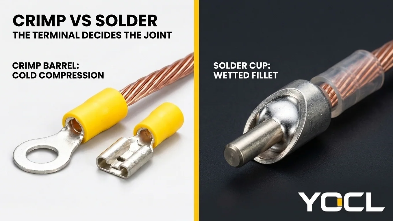
Choosing between crimp vs solder terminals is a terminal-design compatibility rule, not a bench preference. A crimp terminal is a qualified cold-compression system where barrel, wire range, and die deform conductor strands into one gas-tight mass—mechanical first and electrical as a result—whereas substituting soft solder filler metal turns a crimp barrel into an untested joint.
The decision rule the whole article serves is direct: attach the terminal by the method the terminal was designed and qualified for. For the crimp terminals used in field wiring, panels, vehicles, and machinery—including every insulated terminal line on YOCL’s site, such as YOCL’s FDD/FDVD pre-insulated female quick-disconnect terminals and YOCL’s RV pre-insulated ring terminals, whose product pages specify crimp barrels and crimp constructions and publish no solder variant—that method is crimping. Solder’s legitimate territory is real and must be named fairly: printed-circuit assembly, static electronics, and terminals designed for soldering, such as solder cups and solder-eye forms. Treating the choice as “crimp good, solder bad” misses the rule; the terminal’s design decides, as reflected across marine standards (ABYC E-11), aerospace workmanship rules (NASA-STD-8739.4A), harness acceptance standards (IPC/WHMA-A-620), and terminal specifications.
To keep adjacent questions separate, note where each neighbour topic lives. What a crimp terminal is belongs to what a crimp terminal is. Solder-tinned wire ends inside screw-clamp terminal blocks belong to tinned stranded wire in terminal blocks—this article is about how the terminal is attached to the wire, not about what a clamp does to a tinned end.
| Scenario | Joint Mechanism | Wire State Outside Barrel | Qualification | Field Decision |
|---|---|---|---|---|
| Crimp barrel + matched die | Cold compression forms one gas-tight mass | Flexible right to barrel entry | Qualified barrel-wire-tool system | Use for crimp-specified terminals |
| Solder cup or PCB pad | Filler metal wets surfaces without fusion | Supported by PCB, cup, or sleeve | Qualified under IPC/WHMA-A-620 | Use where designed for soldering |
| Crimp barrel + solder only | Soft filler is sole bond in uncrimped barrel | Wicking creates a rigid rod | Prohibited as sole bond (ABYC E-11) | Reject; cut back and re-crimp |
| Pre-tinned wire, then crimped | Die compresses barrel onto rigid solder slug | Soft solder creeps under pressure | Prohibited by aerospace rules (NASA-STD-8739.4A) | Never tin strands before crimping |
Selection Rule: Choose cold-compression crimping with a matched die whenever terminating stranded wire into a crimp-specified barrel (such as ring, spade, quick-disconnect, or tubular lug terminals); switch to soldering only when terminating conductors into dedicated solder cups, solder-eye posts, or rigid printed-circuit boards equipped with mechanical strain relief.
What Each Process Actually Makes: The Cold Compression Joint vs the Filled Joint
Cold-compression wire crimping and capillary solder wetting create fundamentally different metallurgical interfaces inside a terminal barrel. A matched crimp die plastically deforms barrel metal and copper strands into a unified, gas-tight mechanical lock without filler metal, whereas soldering bridges surfaces with a cast tin-alloy filler that remains softer than copper under mechanical load.
In a cold compression crimp, stripped stranded wire enters a barrel whose wall thickness, temper, and serrations match a defined wire range. As the matched dies close, compression exceeds the yield strength of both barrel and strands. Round strands flatten into polygons against one another and the barrel wall, wiping away surface films, extruding air, and locking metal surfaces under elastic clamping stress. Copper bears directly against copper or tin-plated brass, keeping oxidation out while leaving strands outside the barrel free to slip as the wire flexes. For sleeve and insulation-system choice across PVC, nylon, and bare barrels, see PVC vs nylon vs non-insulated crimp terminals.
A soldered joint makes a filled joint rather than a compressed or welded one. As NASA-STD-8739.4A defines it, soldering joins clean metallic surfaces through the use of solder without direct fusion of the base metals. Flux cleans oxides while heat brings strands and barrel to wetting temperature, drawing molten solder between them by capillary action. Once solidified, the solder forms a conductive filler matrix that conducts well on day one. Mechanically, however, the copper strands are not plastically locked to the barrel wall; they sit in a cast filler matrix softer than copper in shear and creep resistance. Inside a solder cup or PCB pad, the terminal body or board carries the mechanical load; inside a flexing crimp barrel, that soft filler is asked to carry stress nobody tested it to withstand.
Why Solder Joints Fail Where Crimps Survive: Wicking, Creep, and the Hard Point
Soldered wire terminals installed in vibrating panels, vehicles, boats, or industrial machinery fail mechanically before failing electrically. Capillary solder wicking stiffens flexible strands into a rigid rod outside the barrel, concentrating bending fatigue at the abrupt hard–soft transition, while solder creep and thermal softening weaken mechanical grip inside the joint.
The primary mechanism is wicking. Stranded wire is used in harnesses because fine copper strands flex easily as individual strands slip relative to one another. When molten solder touches heated stranded wire, capillary action draws liquid solder up between the strands, beyond the barrel, turning a length of flexible conductor into a rigid rod.
That wicked section creates the hard point—an abrupt hard–soft transition just outside the joint. As documented in NASA-STD-8739.4A, a soldered stranded conductor is rigid up to the point where wicking stops and flexible beyond it. Flexing and vibration then concentrate at the hard–soft transition just outside the joint, and strands fatigue and break there—this is the classic field failure.
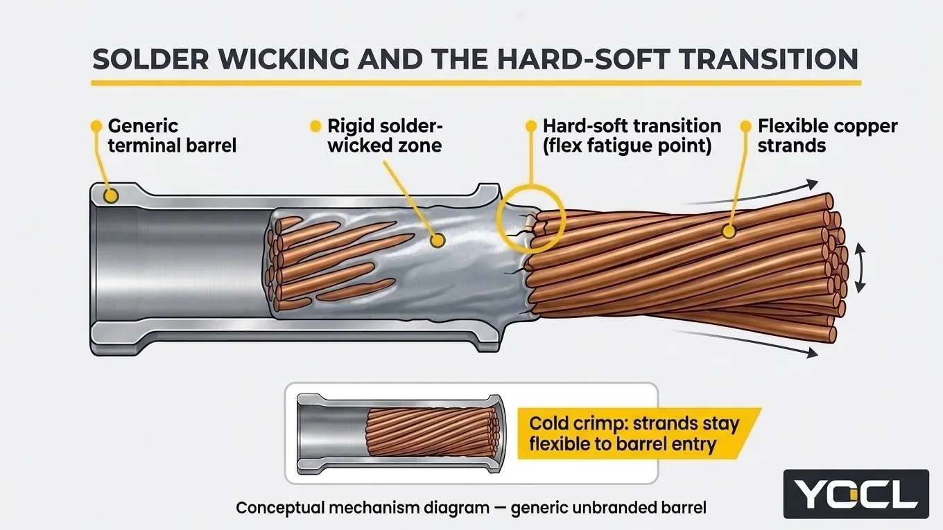
Inside the barrel, solder is also subject to creep and softening. Solder deforms slowly under sustained load and thermal cycling, and loses strength well below copper’s working range if a circuit overheats; a joint that depends on solder alone for mechanical grip is depending on the weakest, softest element in the assembly.
A correct crimp behaves differently. Compression cold-flows barrel and strands together, the conductor stays flexible right up to the barrel, and the joint’s pull strength is a tested property of the terminal system—those numbers live in hammer crimp vs hydraulic crimp for battery lugs and in makers’ data. None of this applies to a joint designed for solder: a solder-cup terminal or a PCB joint is engineered around solder’s properties, with the board or the terminal body providing the mechanical support the solder lacks.
The Three Wrong Orders: What Happens When Methods Are Substituted or Mixed
Field failures in wire-terminal assemblies consistently trace to three improper shop sequences applied to crimp-specified terminals: soldering instead of crimping, pre-tinning stranded wire before crimping, or soldering after crimping. Each sequence alters the qualified barrel-to-wire interface through filler-metal shear, cold-flow relaxation, or capillary wicking at the conductor exit.
Solder Instead of Crimping a Crimp Terminal
Filling an uncrimped terminal barrel with solder instead of compressing it with a matched die leaves soft filler metal as the joint’s only mechanical bond while stiffening the wire exit. Under ABYC E-11 marine electrical rules, “Solder shall not be the sole means of mechanical connection in any circuit.”
ABYC E-11 (AC and DC Electrical Systems on Boats) also specifies that solderless crimp-on connectors are to be attached with the tool type designed for the connector. As commentators record ABYC E-11’s reasons, solder creates a hard spot that resists flexing and vibration poorly, and solder can soften if the circuit overheats. While ABYC E-11 is a voluntary marine standard rather than a universal electrical code, its reasoning generalizes to any vibrating installation.
Tin First, Then Crimp (Pre-Tinning Strands Before the Barrel)
Pre-tinning stripped copper strands with solder before inserting them into a crimp barrel defeats cold-compression locking and causes contact relaxation over time. Aerospace workmanship rules prohibit crimping solder-tinned wire (NASA-STD-8739.4A) because soft solder creeps under sustained barrel pressure and prevents individual copper strands from flowing into a gas-tight mass.
A crimp barrel needs individual copper strands to deform and flow under die pressure; the tinned section is stiff right where the barrel needs strands to flow. Once crimped, the barrel presses on soft solder rather than direct copper-to-metal contact. Because solder is softer than copper and creeps under sustained pressure, the joint relaxes over time and resistance climbs. Framed as aerospace workmanship discipline, the rule reflects universal contact physics.
Crimp First, Then Add Solder “for Extra Strength”
Crimping a wire terminal first and flowing solder into the barrel afterward sits between two distinct, documented engineering positions that must be weighed without merging them. ABYC E-11 permits post-crimp soldering because mechanical grip is already established, whereas terminal manufacturers and harness guidelines advise against altering a qualified crimp-only barrel.
First, ABYC E-11 does not prohibit soldering a connection that is already mechanically made. Crimp first, then solder, is permissible in its framework, because the crimp provides the mechanical connection and solder is not the sole means of connection.
Second, terminal makers qualify their barrels as crimp-only systems, and harness-industry guidance advises against adding solder to a finished crimp. The heat and wicking stiffen the conductor at the barrel exit, damage pre-insulated sleeves, and can mask a bad crimp instead of fixing it.
The resolution is clear: a good crimp gains nothing measurable from solder; a bad crimp is hidden, not repaired—remake it.
Where Solder Is the Right Answer: Solder-Designed Terminals and Static Assemblies
Soldered wire terminations remain a reliable, industry-qualified connection method whenever the terminal geometry or circuit assembly is engineered specifically for solder wetting and external strain relief. IPC/WHMA-A-620 (Requirements and Acceptance for Cable and Wire Harness Assemblies) publishes workmanship acceptance criteria for both crimped and soldered terminations where each is specified.
Soldering is the right, qualified answer across three established applications:
- Printed-circuit assembly: Through-hole leads, board-in terminations, and surface-mount pads use the rigid PCB to support the joint mechanically so the solder fillet carries no free-span bending loads.
- Static electronics: Inside fixed enclosures where conductors are clamped or potted, soldered joints face neither vibration at the wetting boundary nor tensile pull on the filler metal.
- Terminals designed for soldering: Cylindrical solder cups (in circular and D-sub connectors) and solder-eye forms (plus turret and bifurcated posts) contain a solder fillet or anchor a wrapped conductor, paired with shrink-sleeve relief.
The Field Decision Checklist for Crimp vs Solder Terminals
Evaluating crimp vs solder terminals during panel building, harness assembly, or field maintenance requires matching the termination method strictly to the connector’s qualified construction. Verify the barrel specification, conductor state, matched tooling, and rework procedure before energizing any circuit exposed to mechanical vibration or thermal cycling:
- Read the terminal’s specified method. Check the terminal construction and product page first. YOCL’s insulated terminal lines—such as the FDD/FDVD pre-insulated female quick-disconnect series (single-crimp FDD and double-crimp FDVD constructions) and the RV pre-insulated ring terminal series—specify crimp barrels and publish no solder variant. Attach crimp terminals by crimping; solder only solder cups, solder-eye forms, and PCB pads.
- Use stranded conductor and the matched tool. Pair crimp terminals with untinned or factory-plated stranded wire and the crimping die designed for that connector (ABYC E-11). For crimping technique, see how to crimp cable lugs.
- Pull-test a sample. Verify that barrel, wire range, and tool produce a sound joint by pull-testing a sample; see hammer crimp vs hydraulic crimp for battery lugs for the proof method.
- Cut back and re-terminate soldered crimp joints. If a joint arrives soldered where a crimp terminal was specified—or with pre-tinned strands in a crimp barrel—cut back and re-terminate, not more solder. Cut past the wicked section to clean, flexible wire and crimp a new terminal.
Frequently Asked Questions
Can I solder a crimp terminal instead of crimping it?
No. A crimp terminal is a qualified cold-compression system—barrel, wire range, and tool working together—and filling an uncrimped barrel with solder leaves soft filler metal as the sole bond. As ABYC E-11 states verbatim: “Solder shall not be the sole means of mechanical connection in any circuit.”
Is crimp-then-solder stronger than crimp alone?
Documented positions differ. Under ABYC E-11, crimping first and soldering afterward is permissible because solder is not the sole means of connection. However, terminal makers qualify crimp barrels as crimp-only systems, and harness-industry guidance advises against adding solder because heat and wicking stiffen the wire exit and can mask a bad crimp. A good crimp gains nothing from solder; a bad crimp is hidden, not repaired.
Why did my soldered wire break right at the joint?
Molten solder wicks by capillary action up between the strands beyond the barrel, turning flexible wire into a rigid rod and concentrating vibration stress at the hard–soft transition outside the joint; see Why Solder Joints Fail Where Crimps Survive: Wicking, Creep, and the Hard Point.
Is tinned wire the same as tinning it myself before crimping?
No. Factory-tinned conductor has individual copper strands tin-plated before stranding, so they stay separate and deform properly in a crimp barrel. Hand-tinning strands before a crimp binds them into a stiff solder slug that creeps under pressure and is prohibited by aerospace workmanship rules (NASA-STD-8739.4A). For tinned wire ends in screw-clamp terminal blocks, see tinned stranded wire in terminal blocks.
References
- ABYC E-11 — American Boat & Yacht Council, AC and DC Electrical Systems on Boats: verbatim sole-connection prohibition, matched-tool rule, and vibration/overheat rationale.
- NASA-STD-8739.4A with Change 4 — NASA, Workmanship Standard for Crimping, Interconnecting Cables, Harnesses, and Wiring: aerospace prohibition on crimping solder-tinned wire and capillary wicking mechanism.
- IPC/WHMA-A-620 — IPC / WHMA, Requirements and Acceptance for Cable and Wire Harness Assemblies: acceptance criteria for both crimped and soldered terminations.
- YOCL ELECTRIC Product Information — FDD/FDVD Pre-Insulating Female Terminals and RV Pre-Insulated Ring Terminal: crimp barrel and single/double crimp specifications with no solder variant.